International Journal of Emerging Technology and Advanced Engineering
Website: www.ijetae.com (ISSN 2250-2459, UGC Approved List of Recommended Journal, Volume 8, Issue 4, April 2018)
Smart Driver Assisting Vehicle System using Raspberry PI
Prof. Amit Choksi
1, Prof. Kaushal Patel
2, Drupad Pandya
3, Yash Dave
41,2,3,4EC Department, BVM Engineering College, V.V. Nagar, Gujarat, India Abstract—The number of deaths is increasing every year
due to accidents it shows inability of humans to drive in continuously changing environment. As a solution to the problem the control of car is being shifted from manual to automatic. Driver assisting systems are systems which are developed to automate, adjust and improve vehicle systems for safety and better driving. The automatic system which is provided to the vehicle is proven to reduce road accidents, by reducing the human error. Here a method for driver assistance is illustrated using Raspberry pi and servo motors, which is intended to assist the driver during driving on well paved and marked road using image processing. The camera will detect the lane guides using image processing algorithms and the servo motor is used control the cars steering for making turns. Servomotor is controlled with help of raspberry pi and motor control module. Also, in addition to the above features obstacle detection and overtaking decision making is done with help of raspberry pi and ultrasonic sensors. All the programming is done in open CV. An effort is made to reduce the cost and increase the simplicity at small scale by using raspberry pi and servomotors.
Keywords – collision avoidance, Gaussian blur, image processing, lane detection, obstacle detection, raspberry-pi, servomotor, ultrasonic sensors.
I. INTRODUCTION
About 1.30 million people die in road crashes each year, on average 3,287 deaths per day. Additionally, 20-50 million are injured or disabled. More than 50% of the road traffic deaths occur among young adults of ages 15-44. Road traffic crashes are 9th leading cause of death and account for 2.2% of all deaths globally. These ever increasing statistics are alarming and needs to be reduced as soon as possible.
To solve this problem the control of driver is being gradually shifted from manual to automatic.
In the proposed work ultra-sonic sensors are used for motion detection, raspberry pi for computation, servo motor for steering control, and camera for image capturing.
The input is in form of image captured by the camera in RGB format this RGB format is converted into grey image and HLS.
This step is followed by blurring an image by a Gaussian function. It is used to typically to reduce image noise and reduce detail. This is called Gaussian blur.
After Gaussian blur is applied the camera frame is subjected to process of thresholding for separating an image into a foreground and background by converting grayscale images into binary images. This is done by exchanging each pixel in an image with a black pixel if the image intensity is less than some fixed constant or a white pixel if the image intensity is greater than that constant. Here HLS- S channel thresholding is used to give better results.
After the image is separated into foreground and background linear scanning is applied for detecting edges of the lanes due to imperfections in either the image data or the edge detector, there may be missing points or pixels on the desired curves as well as spatial deviations between the ideal line/circle/ellipse and the noisy edge points as they are obtained from the edge detector. This problem can be solved by applying Hough transform by using voting procedure which is carried out in a parameter space, from
Which object candidates are found as local maxima in a so called accumulator space that is clearly constructed by the algorithm for computing the Hough transform.
Now after lane detecting lanes poly fill function is used to fill and mark the area between the lanes with green colour this guides the car to stay between the lanes.
The offset detection and radius of curvature is calculated with reference centre line in order to turn the steering left or right according to the curve of the lane. This information is feed into raspberry pi and servo motor.
International Journal of Emerging Technology and Advanced Engineering
Website: www.ijetae.com (ISSN 2250-2459, UGC Approved List of Recommended Journal, Volume 8, Issue 4, April 2018)
[image:2.612.48.297.122.314.2]II. HARDWARE AND SOFTWARE
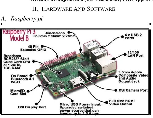
Figure 1: Raspberry Pi Diagram
The Raspberry Pi is small single-board computer. There are presently five Raspberry Pi models in market i.e. the Model A+, the Model B, the Model A, the Model B+, and the Compute Module (presently only available in the Compute Module development kit). All models use the same System on Chip - combined CPU & GPU, the BCM2835, but other hardware structures differ. The A & B use the same PCB, whilst the A+ and B+ are a new design but of very similar form factor [1]. In this method, we have used the model 3 B+ . It comprises of a 1 GB RAM model with two USB ports and a 10/100 Ethernet controller [1].Here we have used Raspberry Pi 3B+ model for illustration of the proposed work. Above model is chosen for its superior processing capacity and effectiveness compared to its previous versions.
B.Raspbian OS
There are many operating systems Risc OS, Arch,
Raspbian or Plan 9 available for Raspberry Pi, Raspbian arises on top as being the best-looking, user-friendly, and
has the best range of default software and optimized for the Raspberry Pi hardware [4]. It is a unrestricted operating system based on Debian (LINUX), which can be downloaded for free from the Raspberry Pi website [4].
C. Pi Camera
It is the camera comes along with Raspberry Pi [2]. The Pi camera module also offers to take high-definition videos and still photographs [2].
D. Ultrasonic Sensors Ultrasonic sensors
The Ultrasonic Sensors are used estimate features of a target by interpreting the echoes from radio or sound waves respectively [3]. In this method, they are used to detect the distance of obstacles from the car [3].The distance measured will be useful for taking decision for overtaking.
E.Python
It is a widely used general-purpose high-level programming language [2,6,7]. Its syntax allows the programmers to express concepts in fewer lines of code when compared with other languages like C, C++or java [6, 7].
F. OpenCV
It (Open Source Computer Vision) is a library of programming functions mainly directed at real-time computer vision. It has over 2500 optimized algorithms, including both a set of classical algorithms and the state of the art algorithms in Computer Vision, which can be used for image processing, detection and face recognition, object identification, classification actions, traces, and other functions [7]. This library allows these features be implemented on computers with relative ease, provide a simple computer vision structure to prototype quickly sophisticated applications [6,7].. It is also used by many research groups and government [7]. It is based on C++ but wrappers are available in python as well. In our method it is used to detect the roads and guide the car on unknown roads [7].
G. RPi.GPIO Python Library
The RPi.GPIO Python library allows one to easily read-write and configure the input/output pins on the Raspberry Pi’s GPIO header within a Python script [2,6]. This is not sent along with Raspbian, but it can be downloaded free of cost.
International Journal of Emerging Technology and Advanced Engineering
Website: www.ijetae.com (ISSN 2250-2459, UGC Approved List of Recommended Journal, Volume 8, Issue 4, April 2018)
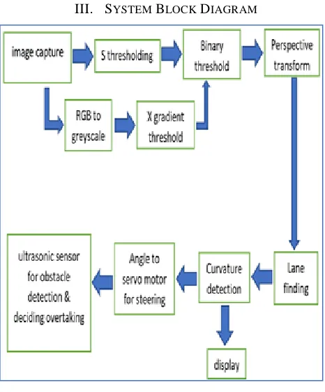
III. SYSTEM BLOCK DIAGRAM
IV. DESCRIPTION OF SYSTEM
A.Image Capture
Image capturing is done through, a 5-megapixel raspberry pi camera which returns the image of 320x192 resolution, with frame rate is 7fps
B.S-channel thresholding
Thresholding with HLS space image is done. Out of hue, saturation, lightness, saturation thresholding is best option for this case. The S channel is does a fairly vigorous job of detecting up the lines under very diverse colour and contrast conditions, while the other selections are rejected. Other thresholds can be squeezed and one can get closer to the other channels, but the S channel is preferable because it is more vigorous to varying conditions.
C.Combination of Binary and S channel thresholding
At this point, it's okay to detect edges around trees or cars because these lines can be mostly filtered out by applying a mask to the image and essentially cropping out
It can be clearly seen which parts of the lane lines were detected by the colour threshold and which parts were detected by the gradient threshold by stacking the channels and seeing the individual components.one can create a binary combination of these two images to map out where either the colour or gradient thresholds were met. The final image colour, binary is obtained by combining binary thresholding the S channel (HLS) and binary thresholding the result of applying the Sobel operator in the x-direction on the original image.
D.Perspective transform
Perspective transform is performed to make lane detection easy by converting image from 3D to 2D. This needs finding of four points on the plane. Assuming a road is a flat plane thus as an estimate for this method, choosing four points in a trapezoidal shape that would represent a rectangle when looking down on the road from above. The simple way to do this is to choose an image where the lane lines are straight and find four points along the lines that, after perspective transform, make the lines appear straight and vertical from a bird's eye view perspective.
E. Finding lane
Usually, lane could be detected by mainly two approaches namely model based technique and feature-based technique. The model-feature-based technique uses a few parameters to characterise the lanes [8,9]. Assuming the shapes of lane can be characterized by either parabolic curve or straight line, the process of detecting lanes is approached as the process of computing those model parameters [8,9]
On the other side the feature-based technique confines the lanes in the road images by combining the low-level features, such as lane edges or painted lines etc [8,9]. Therefore, this technique requires well studied road having strong lane edges or well painted lines, otherwise it will fail. But, it has the drawback of not imposing any global constraints on the lane edge shapes, thus this method may suffer from occlusion or noise [8,9].
In the proposed algorithm to detect the lanes, a feature model base is used. In common, this algorithm is valid for all kind of roads which are marked with white lanes or yellow lanes.
The overall method consists of 6 major parts:
[image:3.612.49.282.130.411.2]International Journal of Emerging Technology and Advanced Engineering
Website: www.ijetae.com (ISSN 2250-2459, UGC Approved List of Recommended Journal, Volume 8, Issue 4, April 2018)
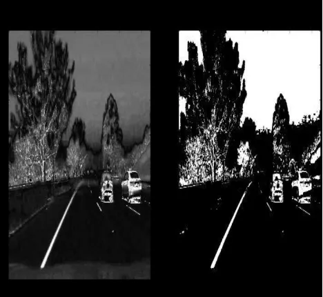
[image:4.612.54.288.291.506.2]2.) S-channel thresholding: After getting the binary image, points of lanes is to be determined. Ideal technique of detection of lane pixels is thresholding, after using quite a lot of image spaces and thresholding, S channel thresholding in HLS image space is noticed as optimum for detection yellow and white colour lanes in any type of lighting conditions. Also this method is able to provide fast conversion of results To avoid, unwanted detection of object other than lanes, we need to binary threshold the captured image. Threshold value of 188 is used in 8-bit image format as threshold value. The final result will be achieved by multiplying both S-channel thresholded image and binary thresholded image.
Figure 3: S-Channel Thresholding
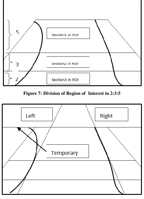
3.) Define the region of interest: A region of interest is defined from lower end towards upper end. As the road image is taken from the camera on the car, the road surface nearest to the car is at the lower end of the image. Thus, the ROI is defined from the nearest region to the further distances by moving upside in the image obtained. The height of the region of interest is usually not greater than half the height of image [11].
This will remove the sky area from the visual field thus saving unnecessary calculations and is better than the method proposed by [11]. As we move further from the car, the width of the road seems to be decreasing. So, the actual
region of interest is in a shape of a trapezium [11]. Figures below show ROI and standard for positive
intercepts.
Figure 4: Define the Region of Interest
Figure 5: Standard for Positive Intercepts
4.) Perspective transform: Perspective transform is an important step to ease the processing and calculation, the perspective image from car is transformed into bird’s eye view. Simply find four points along the lines that, after perspective transform, make the lines appear straight and vertical from a bird's eye view perspective
Region of interest
Y
-
Intercept
+
ve
+
ve
International Journal of Emerging Technology and Advanced Engineering
Website: www.ijetae.com (ISSN 2250-2459, UGC Approved List of Recommended Journal, Volume 8, Issue 4, April 2018)
Original Bird’s eye view
5.) Filtering the noise: The lines along the left edgeof the road are tilted towards right and vice versa. So, any line which is tilted towards left and lies entirely in the left half the image is discarded. Similar lines are also discarded from the right half [13]. For the left edge, a line with the smallest angle or having the least positive x intercept or y intercept is chosen as the left edge of the road. Similarly, find the right edge of the road.
6.)Method to find line: finding peaks in a Histogram. After implementing calibration, perspective transform and thresholding to a road image, we have a binary image which shows the line of lanes clearly. Next we have to clearly decide which pixels are part of the lines and which belong to the left and right line. With obtained histogram, totalling up the pixel values along each column in the image. In the thresholded binary image, pixels have values either 0 or 1, so the two most noticeable peaks in this histogram will be good indicators of the x-position of the base of the lane lines.
Using it as a starting point for searching the lines. From that point onwards, sliding window is placed around the canter of the line, to find and join the lines upward to the top of the frame.
F. Curvature detection
1.) Determine the turns in the road: The different cases of the road which may be met by the vehicle traveling on the highway or any well marked road. Firstly there may be a
To detect the left curvature of the road, divide the region of interest in 3 parts in ratio 2:3:5, compare the lines obtained in all three parts with the possible shape of the road that is each part will be compared to the straight, right and left curving line after comparison road resembling to left or right curve is taken into consideration for Polly fill function. The spotted lines in each section in figure indicate the lines that are obtained by applying Hough transform lines in these sections individually. Once the lane line pixels are found, using the x and y location of those pixels to fit a polynomial curve. In this instance, for a second order polynomial: f(y) = Ay2 + By + C. We want to fit for f(y), then f(x) because the lane lines in the image which is wrapped are close to vertical and can have the matching x value for more than one y value. Now that the curve is detected the polynomial fill function fills the the region between the two lanes which is indicated by green colour in figure 9.after the curvature is detected the next step will be calculating radius of curvature which will notify servo motor to turn steering accordingly.
[image:5.612.48.287.152.325.2] [image:5.612.323.565.376.711.2]International Journal of Emerging Technology and Advanced Engineering
Website: www.ijetae.com (ISSN 2250-2459, UGC Approved List of Recommended Journal, Volume 8, Issue 4, April 2018)
2.) The radius of Curvature: This is used for deciding the amount of curvature of the lanes turning towards right or left based on which car’s steering also needs to be turned accordingly. The radius of curvature at any coordinate x of the function x=f(y) is given by:
[image:6.612.324.554.127.325.2]We could do this by measuring the physical lane in the field of view of the camera, but for this instance, we can assume that if the lane is about 30 meters long and 3.7 meters wide. Or, if you prefer to derive a conversion from pixel space to world space in your own images, compare your images with Indian National Highway regulations that require a minimum lane width of 12 feet or 3.7 meters, and the dashed lane lines are 11.4 feet or 3.5 meters long each.
Figure 9: Lane Detection and Curvature Detection
G. The offset to the servo motor
[image:6.612.49.288.288.453.2]The percentage offset (deviation from the centre line) is used to determine how deviated the centre of the vehicle is from the centre of the curved lane at a given instant of the time. The percentage offset is calculated when both lane markings are detected. It is calculated by using the distance formula based on (Pythagorean Theorem), using the closest points of the detected lane markings comparative to the vehicle. The relative offset is mapped with the turning angles of the servo motor and corresponding PWM signals are sent to the servo motor so that it can turn the steering of the vehicle towards right or left to keep the car between the lanes and avoid accident. Finally with help of continuous feedback loop between raspberry pi and servo motor the rotation of steering is done. The interfacing is shown in figure 10.
Figure 10: Interfacing of Raspberry Pi with Servo Motor
H. Avoiding Obstacles and overtaking decision making using Ultrasonic Sensor
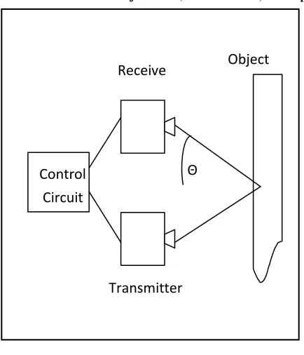
It is the task of fulfilling the control objective focused on non-intersection or no collision position constraints [3]. Normally obstacle avoidance comprises the pre-calculation of an obstacle-free path along which the Raspberry Pi will then guide a car. Another way is to use inverse perspective mapping to find the distance of the objects away from the car with the help of recognised camera parameters and generating a model but it takes more calculations. In the proposed work we have used ultrasonic sensor as it doesn’t require high CPU calculations and identifies the obstacles also it helps us in finding the distance [15] [16]. It is a very low power device and has a very widespread use in mini autonomous robots and cars. The working can be explained as sending a low frequency sound from the sensor’s transmitter to the object which after reflection from the object it is received by the receiver of the sensor. Depending on the time taken to receive the reflected signal, the distance of the nearby vehicle or any other obstacles can be calculated. One shortcoming of this approach is if the reflecting surface is at certain angle to the sensor the distance measured can be unclear [3] and has to be supported with other techniques like OpenCV and image processing before making any decision about the turn. The main application of ultrasonic sensors here is to provide a safe range for overtaking by measuring distances from neighbouring vehicles and decide safe range by comparing it with pre decided safety measures. Figure 11 shows its concept.
International Journal of Emerging Technology and Advanced Engineering
[image:7.612.58.275.124.377.2]Website: www.ijetae.com (ISSN 2250-2459, UGC Approved List of Recommended Journal, Volume 8, Issue 4, April 2018)
Figure 11: Working of Ultrasonic Sensor
The ultrasonic sensor is mounted on the front of the chassis of the vehicle. The sensor regularly and checks for the potentially threatening obstacles which may or may not be in the contour of motion but may hit the car if safety measure is not taken.
Algorithm:
Watch the surrounding after a fixed interval of time i.e. 350ms. The following steps are repeated every interval.
1. Watch the surroundings to calculate the distance of the obstacles from the car.
2. The minimum threshold distance that is safe for the car is 1 metre. If the distance calculated comes out to be lesser than threshold, notify the driver with a alarm 3. Slow down the car and continue monitoring. 4. The minimum threshold distance that is safe for the
car is 1 metre. If the distance calculated is more than threshold, notify the driver to overtake.
5. Rotate the car steering and move ahead.
V. CONCLUSION AND FUTURE WORK
The proposed work shows how a cost effective smart driver assisting system can be built with help of Raspberry Pi and servomotor which will greatly help to reduce loss of
In future we are working to further to develop a system with acceleration control, overtaking vehicles ahead of it, detecting road sign and further GPS module (Google maps) can be added to know the route with least traffic so that car can be automatically driven in less density traffic and highly dense traffic will force manual handling of the car.
Acknowledgement
We are highly grateful to (Prof. Amit H. Choksi and Prof. Kaushal Patel) for their direction and constant supervision as well as for providing necessary information concerning the project & also for their provision in completing the project. We also extend our thanks and appreciations to BVM Engineering College, in developing this project and individuals who have willingly helped us out with their skills.
REFERENCES
[1] Stewart Watkiss, Design and build a Raspberry Pi robot David Hayward, Raspberry Pi operating systems
[2] Johann Borenstein & Yoram Koren, Obstacle Avoidance with Ultrasonic Sensors, IEEE JOURNAL OF ROBOTICS AND AUTOMATION, VOL. 4, NO. 2, APRIL I988, pp. 213-218 [3] Matt Richardson, Shawn Wallace, Getting Started with Raspberry
Pi, 2nd Edition, Published by Maker Media, Inc., USA, 2014. Book
ISBN: 978-1-457-18612-7
[4] Gary Bradski, Adrian Kaehler, Learning OpenCV: Computer Vision with the OpenCV Library, "O'Reilly Media, Inc.". Copyright.
September 2008, 1st Edition, Book ISBN: 978-0-596-51613-0
[5] Gary Bradski, Adrian Kaehler, Learning OpenCV: Computer Vision with the OpenCV Library, "O'Reilly Media, Inc.". Copyright.
September 2008, 1st Edition, Book ISBN: 978-0-596-51613-0 [6] Ch. Krishnaveni, Ms. A. Siresha, Mr. B. J. Prem Prasana Kumar &
Mr. K. Sivanagireddy, Implementation of embedded systems for pedestrian safety using haar features, IJEC: International Journal of Electrical Electronics and Communication, ISN 2048 – 1068, Volume: 06 Issue: 20 l Oct -2014, pp. 761-766
[7] Yue Wanga, Eam Khwang Teoha & Dinggang Shenb, Lane detection and tracking using B-Snake, Image and Vision Computing 22 (2004), available at: www.elseviercomputerscience.com, pp. 269–280.
[8] Tushar Wankhede & Pranav Shriwas, Design of Lane Detecting and Following Autonomous Robot, IOSR Journal of Computer Engineering (IOSRJCE) ISSN: 2278-0661 Volume 2, Issue 2 (July-Aug. 2012), pp. 4548
[9] R. Cucchiara, C. Grana, M. Piccardi & A. Prati, Detecting moving objects, ghosts, and shadows in video streams, IEEETransactions on Pattern Analysis and Machine Intelligence(PAMI), Vol. 25(10), 1337 - 1342, 2003. pp.25-28
[10] H. Dahlkamp, A. Kaehler, D. Stavens, S. Thrun, and G. Bradski. Self-supervised monocular road detection in desert terrain. G. Sukhatme, S. Schaal, W. Burgard, and D. Fox, editors& Proceedings
Transmitter
Control
Circuit
Θ
International Journal of Emerging Technology and Advanced Engineering
Website: www.ijetae.com (ISSN 2250-2459, UGC Approved List of Recommended Journal, Volume 8, Issue 4, April 2018)
[11] H. Dahlkamp, A. Kaehler, D. Stavens, S. Thrun, and G. Bradski. Self-supervised monocular road detection in desert terrain. G. Sukhatme, S. Schaal, W. Burgard, and D. Fox, editors& Proceedings of the Robotics Science and Systems Conference, Philadelphia, PA, 2006.
[12] A. Bar Hillel, R. Lerner, D. Levi, & G. Raz. Recent progress in road and lane detection: a survey. Machine Vision and Applications, Feb. 2012, pp. 727–745
[13] Narathip Thongpan, & Mahasak Ketcham, The State of the Art in Development a Lane Detection for Embedded Systems Design, Conference on Advanced Computational Technologies & Creative Media (ICACTCM’2014) Aug. 14-15, 2014
[14] Li, M., Zhao, C., Hou, Y. & Ren, M., A New Lane Line Segmentation and Detection Method based on Inverse Perspective Mapping, International Journal of Digital Content Technology and its Applications. Volume 5, Number 4, April 2011, pp. 230-236
[15] Dhaval Chheda, Divyesh Darde & Shraddha Chitalia, Smart Projectors using Remote Controlled Raspberry Pi, International Journal of Computer Applications (0975 – 8887), Volume 82 – No. 16, 2013, pp.6-11
[16] Figure 4, 5, 7, 8, 11: International Journal of Computer Applications (0975– 8887) Volume 113 – No. 9, March 2015 22 Design and Implementation of Autonomous Car Using Raspberry Pi [17] Figure10:https://www.raspberrypi.org/forums/viewtopic.
php?t=18280
[18] Figure1: http://datashop.com.br/site/index.php?route= product/product&product_id=12157