International Journal of Emerging Technology and Advanced Engineering
Website: www.ijetae.com (ISSN 2250-2459, ISO 9001:2008 Certified Journal, Volume 4, Issue 9, September 2014)
211
Digital RF Memory Based Target simulator For Radar.
K. Rajitha
1, T. Venkata Rao
2, B. Sudhakar
31PG Student, 2Associate Professor, Sreenidhi Institute of Science & Technology (SNIST), Hyderabad, India 3Scientist, Defence Research and Development Laboratory (DRDL), Hyderabad, India
Abstract--- Idea of Radar target simulator is to electronically generate the Radar illuminated environment without switching on actual Radar transmitter in the field. These Radar target simulators are used to develop, optimize and test the Radar System Design and Algorithms in the Lab. Conventional testing method has its own limitations. In this paper DRFM based target simulator is presented which overcome the conventional method limitations.
Keywords-- DRFM Digital Radio Frequency Memory, FPGA Field Programmable Gate Array, SSB Single Sideband, DDS Direct Digital Synthesis.
I. INTRODUCTION
The functionality of short range Radar is detecting the range and velocity. To Test the capability of Radar system, the field trails are normally carried out in the remote places and these trails are includes lot of efforts and results into lot of expenditure. We cannot test the performance of the system in all the possible scenarios.
Instead an alternate test setup may be designed, which will simulate the real scenario and evaluate the short range Radar performance in different scenarios and with the results we can do the any modification of Hardware or software such that it fulfils all the required functions in all the test conditions. This simulation reduces the testing phase of system development, and all the possible scenarios we can study the system response, which otherwise not possible in real world.
II. RADAR TESTING USING CONVENTIONAL METHOD
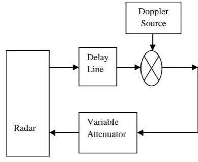
The conventional method for testing the RADAR System is shown in fig 1. The main Functionality of any primary RADAR System is to detect the target range based upon the delay between transmitted pulse and received pulse and target velocity, based upon the Doppler shift between transmitted frequency and received frequency.
[image:1.595.327.522.205.364.2]In this method range is simulated using delay lines and target velocity is simulated using signal generator and RF mixer.
Fig 1: RADAR System testing using conventional method.
The conventional method is having its own advantages and disadvantages.
The merit of conventional method is simple. The demerits of conventional method are :
As the range (i.e. Delay) is added the loss will increase so we need to add amplifiers in between in order to maintain the minimum signal level.
Quadrature null effect: It is the problem of adding Doppler by DSB-Sc method where both positive and negative Doppler signals are added. But in the real scenario, either positive or negative frequency will exist so we have to add the Doppler using SSB modulation.
III. DRFMARCHITECTURE
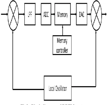
DRFM is the significant block in RADAR Simulators. The basic idea of the DRFM can be found in reference [1]. A basic block diagram of DRFM system is shown in Fig.2 [1]. The modern application example for RADAR simulator found in reference [2]. The Basic Functionality of DRFM technique is to down convert the incoming RF Signal (Normally in GHz) to an Intermediate Frequency (IF Normally in MHz) and the sampled at Higher sampling rate that satisfy the Nyquist Theorem. Then store the digitized signal in High Speed Memory.
International Journal of Emerging Technology and Advanced Engineering
Website: www.ijetae.com (ISSN 2250-2459, ISO 9001:2008 Certified Journal, Volume 4, Issue 9, September 2014)
212
The Memory modules adds the delay and Doppler for simulate the target Range and velocity. The digital Signal is reconstructed by DAC and then Up-converted back to RF frequency using the same Local Oscillator which has been used for down-conversion of the input RF signal.In simple terms the DRFM Memories maintains the coherency of the incoming signal and modifies the phase of the signal to simulate any target.
Fig2. Block diagram of DRFM system.
IV. DRFMBASED DYNAMIC TARGET SIMULATOR
[image:2.595.57.270.232.439.2]The demerits of conventional method are overcome by using DRFM based target simulator. It contains ADC, DAC and a memory module which is implemented by FPGA. The incoming RADAR pulse is modified in the FPGA in phase and spectrum to simulate the required target.
Fig 3.Functional block DRFM Based RADAR Target Simulator.
The FPGA consists of a vast array of configurable logic tiles, multipliers, and memory resources. This technology provides the signal-processing engineer with the ability to construct a custom data path that is tailored to the application at hand.
The delay and Doppler blocks are implemented on Xilinx System generator. The delay block is implemented using shift registers and FIFO modules. The delay is the value in steps of 8.3nsec is the delay that need to added between the input and output. For high values of delay FIFO modules are used for low value of delay shift registers are used.
R A D A R
RF Down convert er
ADC
FPGA adds Delay and Doppler
DAC
G UI
RF UP Con vert er Vari
International Journal of Emerging Technology and Advanced Engineering
Website: www.ijetae.com (ISSN 2250-2459, ISO 9001:2008 Certified Journal, Volume 4, Issue 9, September 2014)
213
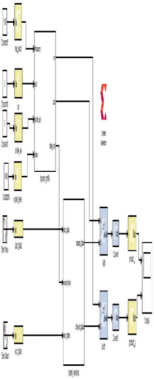
The Doppler block is implemented using DDS. A digitally-controlled method of generating multiple frequencies from a reference frequency source has evolved called Direct Digital Synthesis (DDS).Fig4. Xilinx sysgen model for target generation.
The model is one red token that is called system generator token, it specifies the actual FPGA used and its clock speed.
Here Xilinx Virtex-4 SX FPGA is used so it is specified in that token and the clock speed is 120MHz is also given in that token. The yellow tokens are In and Out tokens that convert the floating point data into fixed point and vice-versa. Since all the logic implementation in FPGA is fixed point so MATLABs floating point values need to be converted into fixed point.
V. RESULTS
[image:3.595.91.244.211.586.2]a.Delay addition
Fig 5. Delay addition
The above figure shows the addition of delay between the input and output. The top Pulse is the input pulse and the bottom pulse is the DRFM output pulse.
Range = CT/2
International Journal of Emerging Technology and Advanced Engineering
Website: www.ijetae.com (ISSN 2250-2459, ISO 9001:2008 Certified Journal, Volume 4, Issue 9, September 2014)
214
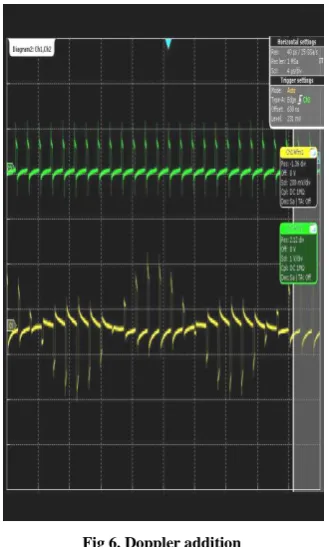
[image:4.595.325.535.137.504.2]b. Doppler Addition
Fig 6. Doppler addition
The required Doppler is generated using DDS, then it is multiplied with the incoming pulses. The above figure shows the video signal of RADAR sensor which having a frequency as well as time shift i.e., velocity and range simulation
Doppler frequency (Fd) = 2 Vr/λ .cos θ
Where λ – wave length and θ-- angle between target and radar.
C. Graphical User Interface.
Fig 7. Shows the GUI that is used to set the test scenario.
[image:4.595.83.248.150.424.2]International Journal of Emerging Technology and Advanced Engineering
Website: www.ijetae.com (ISSN 2250-2459, ISO 9001:2008 Certified Journal, Volume 4, Issue 9, September 2014)
215
VI. CONCLUSION
The Dynamic DRFM Based Target Simulator has been
developed which overcome the limitations of
conventional method limitations. The software coding in VHDL is done for generating a Target with various range and velocities. The Primary target detection capability under various test conditions has been evaluated.
REFERENCES
[1] S. J. Roome “Digital radio frequency memory” ELECTRONICS & COMMUNICATION ENGINEERING JOURNAL AUGUST 1990
[2] Zongbo Wang Meiguo Gao Yunjie Li Haiqing Jiang Sunguo Ying “The Hardware Platform Design for DRFM System” ICSP2008 Proceedings IEEE
[3] “Doppler frequency estimation with wavelets and neural networks” by Steven E. Noel, Harold H. Szu, and Yogesh J. Gohel Naval Surface Warfare Center Dahlgren Division, Dahlgren, VA 22448
[4] M. I. Skolnik, Introduction to Radar Systems, Third Edition, The McGraw-Hill Companies, Inc, 2001.
[5] www.xilinx.com.
[6] Guide for Xilinx System Generator from Xilinx.
[7] V. Oppenheim and A. S. Willsky, Signals and Systems, Prentice-Hall, Uppersaddle River, NJ, 1996.
[8] August W. Rihaczek, Principles of High Resolution Radar, McGraw-Hill: New York, NY, 1969.