VISUOMOTOR BEHAVIOURS DURING FUNCTIONAL TASK
PERFORMANCE WITH A MYOELECTRIC PROSTHESIS
Mohammad M. D. Sobuh
VISUOMOTOR BEHAVIOURS DURING FUNCTIONAL TASK
PERFORMANCE WITH A MYOELECTRIC PROSTHESIS
Mohammad M. D. Sobuh
Centre for Health, Sport and Rehabilitation Sciences Research
School of Health Sciences
University of Salford, Salford, UK
i Contents
Contents ... i
List of Figures... vi
List of Tables ... ix
Acknowledgements ... x
List of abbreviations... xi
Abstract ... xiii
Chapter 1: Introduction ... 1
Chapter 2: Literature Review ... 4
2.1. Introduction ... 4
2.2. The anatomical hand and its function ... 4
2.3. Reaching and manipulation ... 8
2.3.1. Kinematics of reaching to grasp ... 8
2.3.2. Vision and proprioception in reaching to grasp ... 9
2.4. Multi-stage functional tasks ... 11
2.4.1. Movement kinematics in multi-stage functional tasks... 11
2.4.2. Vision in multi-stage tasks ... 11
2.5. Learning to use a hand-held tool to reach and grasp ... 13
2.6. Amputation ... 16
2.6.1. Levels of amputation ... 16
2.6.2. Incidence of upper limb amputation ... 17
2.7. Upper limb prostheses ... 18
2.7.1. Body powered prostheses... 19
2.7.2. Myoelectric prostheses ... 19
2.8. Clinical measures of function ... 26
2.8.1. Interviews/questionnaires based evaluation of the functionality ... 26
2.8.2. Clinical observational tests ... 27
2.9. Usage, acceptance and rejection rates ... 29
2.10. Motor behaviours characterising upper limb myoelectric prosthesis use ... 31
2.10.1. Kinematics of pointing in established trans-radial amputees ... 31
2.10.2. Kinematics of reaching to grasp in trans-radial prosthesis users ... 32
2.10.3. Upper limb movement characteristics in complex manual tasks ... 35
2.10.4. Characteristics of learning to use prostheses ... 35
2.11. Conclusions and thesis aims ... 43
ii
3.1. Introduction ... 46
3.2. Methods ... 50
3.2.1. Task selection ... 50
3.2.2. Subjects ... 53
3.2.3. Data collection ... 53
3.2.4. Experimental setup ... 54
3.2.5. Task performance ... 55
3.2.6. Instrumentation for gaze data capturing and initial processing ... 55
3.3. Development of the coding scheme ... 57
3.3.1. Description of AOIs ... 57
3.3.2. Dimensionality discrepancy... 60
3.4. Coding scheme reliability and comparison with a simple coding scheme ... 61
3.4.1. Data analysis ... 61
3.4.2. Statistical analyses ... 62
3.4.3. Results ... 63
3.5. Discussion... 67
3.6. Conclusion ... 69
Chapter 4: Changes in upper limb kinematics and gaze behaviour during learning to use a myoelectric prosthesis ... 71
4.1. Introduction ... 71
4.1.1. Kinematics ... 71
4.1.2. Vision... 73
4.2. Methods ... 74
4.2.1. Instrumentation... 76
4.2.2. Task performance ... 79
4.3. Data analysis ... 81
4.3.1. SHAP sessions ... 81
4.3.2. Visuomotor sessions (V sessions) ... 82
4.4. Statistical analyses ... 91
4.4.1. The SHAP sessions ... 92
4.4.2. The visuomotor performance sessions (V) ... 92
4.5. Results... 93
4.5.1. SHAP scores and task completion time... 93
4.5.2. Kinematic data... 95
iii
4.6. Discussion... 109
4.6.1. SHAP scores and task completion time... 109
4.6.2. Kinematic data... 109
4.6.3. Gaze data ... 113
4.7. Conclusions ... 118
Chapter 5: Visuomotor behaviours during performance of a functional task in amputees who use myoelectric prostheses and their relationships with established clinical measures... 120
5.1. Introduction ... 120
5.2. Methods ... 122
5.2.1. Subjects ... 122
5.2.2. Testing procedure ... 125
5.3. Data analysis ... 130
5.3.1. Clinical evaluation tools ... 130
5.3.2. Kinematic and gaze data ... 132
5.3.3. The correlation between clinical evaluation tools and measures of skill ... 133
5.4. Results... 133
5.4.1. Upper limb prosthesis clinical evaluation tools ... 134
5.4.2. Kinematic data... 137
5.4.3. Gaze behaviours ... 151
5.4.4. The correlation between clinical evaluation tools and measures of skill ... 164
5.5. Discussion... 166
5.5.1. Upper limb prosthesis clinical evaluation tools ... 166
5.5.2. Movement kinematics of session 2 ... 169
5.5.3. Gaze data of session 2 ... 176
5.6. Conclusion ... 180
Chapter 6: Discussion and conclusions ... 183
6.1. Introduction ... 183
6.2. Future work ... 188
6.2.1. Insights into the design of prosthetic devices with artificial feedback ... 189
6.2.2. Assessment of training outcomes ... 190
6.2.3. Gaze behaviour training ... 190
6.2.4. Automating gaze coding and characterising gaze behaviour during performance of the SHAP test ... 191
6.3. Thesis limitations ... 191
iv
6.3.2. Task segmentation ... 192
6.4. Novel work in the thesis ... 192
Appendix A: The AOIs ... 194
A.1. The confusion matrix ... 199
Appendix B: Validation of simulated accelerometer data ... 200
B.1. Introduction ... 200
B.2. Methods ... 200
B.2.1. Instrumentation and setup ... 200
B.2.2. Data capturing... 201
B.2.3. Data analysis ... 202
B.2.4. Statistical analysis ... 202
B.3. Results... 203
B.4. Discussion and conclusions ... 204
Appendix C: Agreement between the two methods for calculating task and phase duration 206 C.1. Introduction ... 206
C.2. Methods ... 206
C.3. Data analysis ... 207
C.4. Statistical analysis ... 207
C.5. Results and discussion ... 207
C.6. Conclusions ... 209
Appendix D: Ethical approval letters ... 210
Appendix E: Statistical analyses (Chapter 4) ... 215
Appendix F: Comparing visuomotor results of the left-handed subject with results of the other right-handed subjects (Chapter 4) ... 218
F.1. SHAP scores ... 218
F.2. Kinematic data ... 218
F.3. Gaze data ... 219
Appendix G: The shoulder centre of rotation (SCR) ... 220
Appendix H: Wrists velocity and hand aperture profiles (Chapter 4) ... 221
Appendix I: Gaze sequence (Chapter 4) ... 228
I.1. Reaching phase... 228
I.2. Manipulation phase ... 232
Appendix J: The Upper Extremity Functional Status of OPUS questionnaire ... 236
v
Appendix L: Poster presented at the BodyRep workshop, Goldsmiths, University of London,
London, UK (2010) ... 238
vi List of Figures
Figure 2. 1 ... 5
Figure 2. 2 ... 6
Figure 2. 3 ... 7
Figure 2. 4 ... 9
Figure 2. 5 ... 12
Figure 2. 6 ... 14
Figure 2. 7 ... 15
Figure 2. 8 ... 17
Figure 2. 9 ... 19
Figure 2. 10 ... 20
Figure 2. 11 ... 21
Figure 2. 12 ... 21
Figure 2. 13 ... 24
Figure 2. 14. ... 33
Figure 2. 15 ... 34
Figure 2. 16 ... 38
Figure 3. 1 ... 49
Figure 3. 2 ... 49
Figure 3. 3 ... 54
Figure 3. 4 ... 55
Figure 3. 5 ... 56
Figure 3. 6 ... 57
Figure 3. 7 ... 58
Figure 3. 8 ... 64
Figure 3. 9 ... 65
Figure 3. 10 ... 66
Figure 3. 11 ... 67
Figure 4. 1 ... 77
Figure 4. 2 ... 78
Figure 4. 3 ... 80
Figure 4. 4 ... 81
vii
Figure 4. 6 ... 84
Figure 4. 7 ... 86
Figure 4. 8 ... 89
Figure 4. 9 ... 91
Figure 4. 10 ... 95
Figure 4. 11 ... 96
Figure 4. 12 ... 97
Figure 4. 13 ... 98
Figure 4. 14 ... 99
Figure 4. 15 ... 100
Figure 4. 16 ... 101
Figure 4. 17 ... 102
Figure 4. 18 ... 103
Figure 4. 19 ... 104
Figure 4. 20 ... 105
Figure 4. 21 ... 106
Figure 4. 22 ... 107
Figure 4. 23 ... 108
Figure 4. 24 ... 108
Figure 4. 25 ... 116
Figure 5. 1 ... 123
Figure 5. 2 ... 125
Figure 5. 3 ... 129
Figure 5. 4 ... 131
Figure 5. 5 ... 137
Figure 5. 6 ... 138
Figure 5. 7 ... 139
Figure 5. 8 ... 140
Figure 5. 9 ... 141
Figure 5. 10 ... 142
Figure 5. 11 ... 143
Figure 5. 12 ... 144
Figure 5. 13 ... 145
viii
Figure 5. 15 ... 149
Figure 5. 16 ... 150
Figure 5. 17 ... 151
Figure 5. 18 ... 152
Figure 5. 19 ... 153
Figure 5. 20 ... 154
Figure 5. 21 ... 156
Figure 5. 22 ... 158
Figure 5. 23 ... 160
Figure 5. 24 ... 162
Figure 5. 25 ... 163
Figure 5. 26 ... 164
Figure 5. 27 ... 165
Figure 5. 28 ... 165
Figure 5. 29. ... 166
Figure 5. 30 ... 174
Figure B. 1. ... 201
Figure B. 2 ... 203
Figure B. 3 ... 204
ix List of Tables
Table 3. 1 ... 52
Table 3. 2 ... 59
Table 4. 1. ... 76
Table 4. 2 ... 78
Table 4. 3 ... 90
Table 4. 4 ... 94
Table 4. 5 ... 94
Table 5. 1 ... 124
Table 5. 2 ... 128
Table 5. 3 ... 134
Table 5. 4 ... 135
Table 5. 5 ... 136
Table 5. 6 ... 139
Table 5. 7 ... 142
Table 5. 8 ... 143
Table 5. 9 ... 147
Table 5. 10 ... 150
Table 5. 11 ... 151
Table 5. 12 ... 154
Table 5. 13 ... 157
Table 5. 14 ... 159
Table 5. 15 ... 161
Table 5. 16 ... 163
Table 5. 17 ... 164
Table A. 1 ... 196
Table A. 2 ... 198
Table A. 3 ... 199
x Acknowledgements
This thesis represents the result of almost four years of research. Since my first meeting with
my supervisors, I realised how difficult and complex the research process is. However, this
spurred me to work harder to make this thesis deserving of mention. Of course, this would not
have happened without the tremendous support and guidance of my supervisors. Therefore, it
is a pleasure to convey my gratitude to them all in this acknowledgement.
In the first place, I am very grateful to Dr. Laurence Kenney for his excellent supervision,
advice, and guidance from the very early stage of this research. Also, thanks to Dr. Sibylle
Thies for her mentorship and support. I convey special acknowledgement to Dr. Adam Galpin
for his advice, supervision, and crucial support for the psychology aspects of the work.
My special thanks go to Prof. Peter Kyberd (University of New Brunswick, Canada) for his
useful suggestions, particularly in the early stages of the work. I am also very grateful to Prof.
Jai Kulkarni and Mrs. Jane McLaughlin for their collaboration and help with subject
recruitment.
I would also like to sincerely thank the students and staff at the Centre for Health, Sport and
Rehabilitation Sciences Research for creating a pleasant working atmosphere and for being
willing to lend a hand.
I would like also to acknowledge the University of Jordan for their support of the work in the
form of travel funds, tuition fees, and living expenses over the period of my studies.
xi List of abbreviations
The following table describes the abbreviations and acronyms used throughout the thesis. The
abbreviations and acronyms are in an alphabetical order. The page on which each
abbreviation is defined, or first used is also given. Acronyms that are used to abbreviate the
labels of the reflective markers and the names of the areas of interest are not included in the
list. The acronyms of reflective markers are reported in Table 4. 2 and Table 5. 2, and of the
areas of interest in Table 4. 3.
Abbreviation Meaning Page
2D Two-Dimensional 60
3D Three-Dimensional 4
ACMC Assessment of the Capacity for Myoelectric Control 28
ADL Activity of Daily Living 3
ANOVA Analysis of Variance 93
AOI Area of Interest 46
CAST Calibrated Anatomical System Technique 76
CI Confidence Interval 96
CNS Central Nervous System 7
COG Centre of Gravity 49
DoF Degree of Freedom 1
ECR Elbow’s Centre of Rotation 84
EMG Electromyographic xiii
GRP Gaze Reference Point 54
HLC High Learning Capacity 37
HRP Hand Resting Position 54
ICC Intra-class Correlation Coefficient 63
ID Index of Difficulty 32
IOF Index of Functionality 81
JCF Joint Coordinate Frames 84
LLC Low Learning Capacity 37
OPUS Orthotics and Prosthetics User Survey 27
OT Occupational Therapist 123
PGA Peak Grasping Aperture 8
xii
PV Peak Velocity 8
RMSE Root Mean Square Error 88
ROM Range of Motion 35
SCR Shoulder Centre of Rotation 84
SD Standard Deviation 63
SHAP Southampton Hand Assessment Procedure 27
SMAS Salford Motion Analysis System 83
TAPES Trinity Amputation and Prosthesis Experience Scales 27
UEFS Upper Extremity Functional Status 27
xiii Abstract
Myoelectric hand prostheses are controlled via electromyographic (EMG) signals measured at
the residual forearm musculature. Active functional use requires control of force and motion
of the prosthetic hand in the absence of proprioceptive and tactile feedback from the hand.
Many amputees often choose not to use their prosthesis in this way in everyday life. Current
clinical tools provide little insight into why this is, and the few studies of motor control
strategies and motor learning provide only a very partial explanation. Further studies are
therefore required to inform the development of new prostheses and improved training
protocols. Moreover, despite the general agreement that amputees compensate for missing
proprioception through vision, at the start of the PhD there were no studies of gaze behaviour
in upper limb amputees. The aims of the thesis were to:
1. To identify visuomotor behaviours that change over learning to use a myoelectric
prosthesis and;
2. To identify the visuomotor behaviours of established users of myoelectric prostheses
and their relationships with results from validated clinical evaluation tools.
To allow investigation of visuomotor behaviours, an everyday task was chosen, namely
reaching for and acquiring a carton, then pouring water from it into a glass. A novel coding
scheme for objective analysis of gaze data during task performance was developed and
validated. Additionally, methods for describing upper limb kinematics were implemented.
Using these tools a study of learning to use a myoelectric prosthesis simulator in anatomically
intact subjects revealed a number of variables whose values change dramatically with the
introduction of the prosthesis and remain different from baseline, even after practice. For
example, subjects remained slower at reaching and more variable in their movement and gaze
behaviour. Additionally, subjects had to pay considerable attention to the immediate task
requirements. The latter findings may be interpreted as showing that prosthesis use may be
attentionally demanding. A second study was then carried out involving established
trans-radial myoelectric prosthesis users. Similar behaviours to those reported in the first study
(following only a very brief period of practice) were observed, giving insight into why current
prostheses remain difficult to use in everyday life; amputees had to pay a high degree of
visual attention to the immediate requirements of the task, thus limiting their ability to plan
subsequent actions of the task. Additionally, subjects who performed well on the task, were
1 Chapter 1: Introduction
Trans-radial myoelectric prostheses are mechatronic devices designed with the aim of
replacing both the function and appearance of the missing anatomy. They possess one or two
active degrees of freedom, each of which is controlled via electromyographic (EMG) signals
measured at the residual forearm musculature. The degrees of freedom (DoF) typically relate
to hand opening and wrist rotation. To achieve functional goals, such as object acquisition and
manipulation, the user must be capable of controlling the relevant EMG signal(s) so as to
operate the prosthetic hand in synergy with remaining, more proximal joints. EMG control
must be accomplished in the absence of proprioceptive feedback from the hand and wrist, a
key source of information for the planning and execution of upper limb functional tasks in
anatomically intact individuals (1).
It is clear that, despite considerable research and development over the years, current devices
do not fully replace the functions of the anatomical hand (2) and poor clinical outcomes are
common (3). For example, it has recently been reported that at least 20% of adult myoelectric
prosthesis users reject their prosthesis, a figure which is similar to that reported more than 20
years ago (3).
Many different tools to evaluate upper limb prostheses have been developed over the years.
Those can be broadly categorised into two groups: tools for measuring a user’s performance
on particular functional tasks and questionnaire or interview-based tools to evaluate, for
example, users’ perceptions of their prosthesis and the extent to which they make use of their
prosthesis (4). Useful information regarding prosthetic hand performance and usage can be
determined with such evaluation tools, and they are well-suited to comparison studies.
However, despite work in the area of upper limb motor control in prosthesis users carried out
in the early 1980s (5, 6), there have been surprisingly few studies describing the characteristic
changes in motor behaviour, and no previous work on visuomotor behaviour, associated with
learning to use a prosthesis. This is despite the widespread agreement regarding the role of the
vision in prosthetic use (6-10). Therefore, nothing is known about the relationships between
visuomotor skill level and more clinically relevant measures, such as usage of the device in
everyday life and acceptance of the prosthesis. Studies in the area of visuomotor control may
lead to the development of improved outcome measures, improved designs and new training
2 The two aims of this thesis are:
1. To identify visuomotor behaviours that change over learning to use a myoelectric
prosthesis and;
2. To identify the visuomotor behaviours of established users of myoelectric prostheses
and their relationships with results from validated clinical evaluation tools.
Chapter 2 introduces the background to the thesis. Upper limb anatomy and functions are
briefly introduced to the reader. Following on from this, the concepts of motor control and
skill acquisition are discussed. For this purpose, the normal visuomotor behaviour in reaching
and grasping, and more complex, multi-stage tasks are described. This is followed by a brief
review of the literature on learning to control hand-held tools.
In the second part of Chapter 2, the focus is on control of myoelectric prostheses. The section
begins with an overview of amputation, its consequences and prosthetic management, with a
particular focus on myoelectric prostheses and the reported difficulties associated with their
use. The clinical evaluation tools to assess upper limb prostheses are then described and
conclusions regarding their limitations are drawn. The literature on the kinematics of upper
limb task performance in amputees is then discussed. Finally, the limited available literature
on learning to use a prosthesis is reviewed.
Conclusions are drawn that lead on to the justification for the two major studies in the thesis –
a study of visuomotor behaviours in anatomically intact subjects learning to use a myoelectric
prosthesis (Chapter 4) and a study of visuomotor behaviours in amputee users of trans-radial
myoelectric prostheses (Chapter 5).
Chapter 3 describes the development of experimental approach for recording and analysing
gaze behaviours during manual task performance, either using the anatomical hand or using a
myoelectric prosthesis simulator. More specifically, the task to be studied is justified and
defined and a coding scheme for objective analysis of the gaze data is described and its
reliability assessed.
In Chapter 4, a study that evaluated the changes to visuomotor (kinematics and gaze)
3
activity of daily living (ADL) task is presented. The study was conducted in anatomically
intact subjects who were fitted with and practiced using a myoelectric prosthesis. The study
identifies a number of visuomotor parameters which differentiate upper limb task
performance with the anatomical hand from performance with a myoelectric prosthesis. Also
it identifies parameters which change over learning to use the prosthesis (termed skill
measures), and hence may reflect skill acquisition.
The study reported in Chapter 5 had two aims. The first was to investigate whether the
visuomotor behaviours seen in subjects using their prosthesis at the end of the study reported
in Chapter 4 are also seen in amputee users of the same type of prosthesis. The second aim
was to investigate the relationships between the new skill measures and current clinical
measures of hand function and the extent to which amputees make use of their prosthesis in
everyday life.
Upper limb unilateral amputees’ use of their prosthesis was investigated using validated
clinical questionnaires, and their performance on a standard, validated clinical hand function
test was measured. The subjects’ performance on the same task as studied in Chapter 4 was
evaluated and the new skill measures for both arms were derived and compared with the
findings in the study of anatomically intact subjects in Chapter 4. Finally, relationships
between the established clinical outcomes and the new gaze and kinematic measures are
described.
Chapter 6 presents an overview of the entire thesis, highlights its limitations and suggests
4 Chapter 2: Literature Review
2.1.Introduction
This chapter begins with an overview of the anatomical upper limb and its function.
Following on from this, the literature on tool use and learning to use a tool are briefly
discussed. The topics of upper limb amputation and myoelectric prostheses and their control
are then introduced. This is followed by a section on outcome measures in which the clinical
tools currently used to investigate upper limb prosthesis use and function are reviewed. The
reader is then introduced to the literature on prosthesis functionality, acceptance and use,
demonstrating that current devices remain far from ideal replacements for the anatomic hand.
Finally, the studies of motor control in prosthesis users and while learning to use a prosthesis
are reviewed. Finally, the need for improved prosthesis evaluation procedures is discussed,
leading up to the specific aim of this thesis: development of outcome measures that
characterize skill in upper limb prosthesis use in ADLs.
2.2.The anatomical hand and its function
The human hand allows us to manipulate objects and to interact with the environment. The
complex sensory motor structure of the upper limb (including the hand) allows for
goal-directed reaching with subsequent coordination and control of small muscle movements in the
fingers - thereby providing us with manual dexterity (11).
With regard to the upper limb’s structure, the hand can be considered the “end effector” in a
chain of more proximal upper limb segments all of which contribute to its effective use as
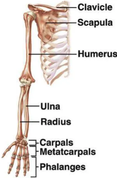
they guide it in 3D space. The upper limb in its entirety comprises 32 articulated bones (see
Figure 2. 1), moved by 67 muscles (12), and contains 4 functional units (shoulder complex,
elbow complex, wrist joint and hand) that allow goal-directed reach and grasp movements
(13). Specifically, the shoulder complex comprises the sternoclavicular joint,
acromioclavicular joint, glenohumeral joint, and scapulothoracic articulation (13) and the
elbow complex consists of the humerus and ulna articulation, normally referred to as the
elbow joint, and the proximal and distal radial ulnar joints (13). The wrist joint is then the
complex articulation of the carpal bones with the radius, with each other, and with the
metacarpal bones (13). With regard to their specific function, the shoulder and elbow joint
complexes provide gross upper limb movement of the hand, and the radial ulnar and wrist
joints are used to orient the hand relative to more proximal joints. Together the shoulder,
5
solutions to a given problem of placing and orienting the hand in space. The specific function
of the hand is then the act of grasping, prehension (14), and object manipulation. In pointing,
the hand normally acts as an extension of the arm with no active involvement of the figures.
[image:20.595.194.394.139.443.2]
Figure 2. 1: Skeletal structure of the upper limb (adapted from (15)).
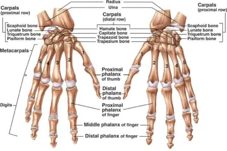
The hand (Figure 2. 2) consists of 19 bones, resulting in 17 articulations with more than 22
DoFs (16) that are controlled by 36 muscles; 19 of which originate within the hand itself and
allow for fine finger movements, and 17 originate in the forearm (12). This highly evolved
structure makes it possible that objects with a wide range of shapes and of different
6
Figure 2. 2: Skeletal structure of the anatomical hand (from (15)).
With regard to the upper limb’s sensory structure, the upper limb is enclosed with skin that
protects the underlying musculoskeletal structures and provides a massive sensory receiver for
many different sensations including pain, touch, pressure, vibration, tickle, itch, thermal
changes, compliance, wetness and roughness (17). In addition, skin has a discriminative
capacity which allows for object recognition (i.e. identification of an object by analysis of its
size, shape, and texture). Specialised mechanoreceptors lie within the skin and provide a
platform for sensory recognition. Non-hairy skin (glabrous skin), particularly palmar skin of
the hand, is highly sensitive to touch allowing for excellent discriminative capacity due to its
high density of mechanoreceptors (17). In fact, the pulp and skin of the fingers contains by far
the highest density of mechanoreceptors in the body (17). This provides an
effective mechanism for sensing the geometric properties of a grasped object and its
compliance which allows fine control of grasp via grip forces (18). The mechanoreceptors
also sense object slippage; they induce a reflex to increase the grip force as soon as slippage is
detected (17). Although sensory information from other modalities such as vision and
proprioception is employed to formulate and regulate the hand grip aperture and grip forces,
the role of mechanoreceptors cannot be fully replaced by other modalities (19). Furthermore,
in addition to the above discussed skin sensations, specific receptors found in skin, skeletal
7
and velocity of a movement and the muscular forces generated to perform a task” (20). By far,
muscle proprioceptive receptors are the most dominant source of proprioceptive feedback
(17). The proprioceptive receptors of skeletal muscles respond to changes in muscle length
and to the forces exerted by the muscle (17). This allows detection of movement and
identification of the location of the upper limb in space in addition to estimating the object’s
weight in the hand (17). In addition to proprioceptive receptors found in muscles, joint
capsules and ligaments comprise proprioceptive receptors that are mostly stimulated at the
extreme range of motion of the joints to prevent further (harmful) movement of the joint (17).
All sensory information from the different receptors is conveyed via ascending neural
pathways to the central nervous system (CNS) and motor commands are delivered via
descending neural pathways in response.
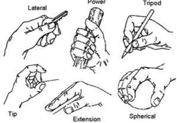
Prehension, the act of grasping an object (21), is achieved using a limited number of patterns.
With 7 DoFs provided by the shoulder, elbow and wrist and approximately 22 DoFs of the
hand, objects can be grasped in a number of ways at any reachable location (11). The task
requirement (how the object will be used) and the object’s physical features (size, shape and
weight) influence the grip chosen to acquire the object (22). Grips may be subdivided based
on the fingers’ configurations into power grip (or transversal volar grip (23)), lateral grip, tip
[image:22.595.85.394.501.715.2]grip, span or spherical grip, tripod grip and extension grip (Figure 2. 3) (24).
8
2.3.Reaching and manipulation
2.3.1. Kinematics of reaching to grasp
When acquiring objects located within a reachable distance from the body, the hand is
transferred to the vicinity of the object to be grasped by the shoulder and elbow joint motion
(the reaching phase) (26). Concurrently, the hand is preshaped appropriately so the object can
be grasped by the end of the reaching phase (26), this biphasic hand opening-closing motion
presents the grasping component. In a functional manual task that requires reaching to grasp
an object located at a fixed distance from the body, certain kinematic characteristics
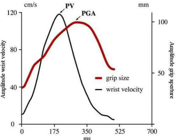
consistently emerge (27, 28). As illustrated in Figure 2. 4, following initiation of a reaching to
grasp movement, the wrist moves rapidly to the object (acceleration phase), reaches a peak
velocity (PV), then decelerates smoothly, resulting in a movement trajectory with a
bell-shaped velocity profile (27, 28).
Mean and peak velocity amplitude are a function of object distance (27, 28); they increase
almost linearly with the increased distance. Furthermore, both peak velocity amplitude and
time to peak also decrease when reaching to grasp smaller or more fragile objects as a result
of the increased accuracy demands (speed/accuracy trade-off) (29, 30). Nevertheless the
bell-shaped velocity profile is maintained (30).
Hand pre-shaping and the initiation of movement of the arm toward the object start almost
simultaneously (~ 50 ms lag) (27, 31). During reaching, the hand normally continues to be
pre-shaped which involves configuring the fingers to achieve an aperture that is larger than
the object size. The relationship between grasping aperture and the object’s size was
established by Marteniuk et al (32); for a 10 mm increase in object size, the grasping aperture
was found to increase by 7.7 mm. Peak grasping aperture (PGA) occurs at 70-80% of the
movement time; around the time of peak deceleration (11) after which the hand starts to close
9
Figure 2. 4: Characteristics of reaching to grasp movement in anatomically intact individuals.
The velocity profile of the wrist and the hand aperture profile are shown as a function of time.
The object was a dowel (1.5 cm in diameter), located 30 cm from the subject and 20⁰ to the
right of its body midline (from (11)). Note that PV denotes peak velocity and PGA peak
grasping aperture.
2.3.2. Vision and proprioception in reaching to grasp
Both vision and proprioception play key roles in planning and correcting movement (1, 33).
Jeannerod in his seminal works suggested that both reaching and grasping are planned based
on visual information accessed during the period prior to movement initiation (27, 28, 31).
According to Jeannerod, the visual information for both reaching and grasping is gathered via
two independent pathways or “visuomotor channels”. The independence of these two
channels implies that information required to plan reaching is not used to plan grasping and
vice versa. For reaching, Jeannerod demonstrated that visual information about an object’s
extrinsic properties (such as orientation, location and distance from the body) are used to plan
the movement of the shoulder and elbow in order to move the hand towards the object. In
turn, information about the object’s intrinsic properties (such as shape, size and texture) is
used to plan the activities of forearm and hand muscles to pre-shape the hand for grasping (27,
28, 31).
In addition to planning movement, visual feedback is essential to correct ongoing movement,
10
guidance of the reaching to grasp movement came from the findings of Jeannerod (28), who
reported about 1-2 cm of object undershooting in the absence of visual information about the
hand location or the object, during reaching to grasp. Blocking the subject’s view of the hand
and/or the object for the entire movement duration were found also to introduce changes to
the reaching and grasping characteristics, including an increase in reaching time (particularly
due to an increase in deceleration phase duration), an increase in hand aperture duration, and
increase in time to peak grip aperture (28, 33, 35-37). Interestingly, overt visual attention to
the hand while reaching to grasp an object is rarely if ever seen and therefore not needed for
controlling the reaching to grasp movement (38, 39). However, it seems that the visual
feedback during reach to grasp comes largely from the peripheral visual field (34). Also,
towards the end of the reaching movement, when the speed of the hand approaching the
object is slowing, the gradual emergence of the hand into the high resolution foveal vision
may be used in the control of grasp (36).
The role of proprioception in reaching and grasping is reviewed in (40). In a broad sense,
proprioception provides intrinsic information about the limb; including its spatial
configuration and movement, as well as muscle forces (40). This information is used by the
CNS to transform the movement plan (derived from the visual information) into appropriate
motor commands to the muscles (40). Proprioception information is critical for controlling
intersegment coordination, as shown in a study by Sainburg et al (41). In this study, where
deafferentated subjects performed an unconstrained 3D task (simulating slicing a bread loaf),
they exhibited abnormally high spatial variability in their movements. Further investigation
of the data revealed that this high variability was because of the temporal decoupling between
the elbow and shoulder joint (41). High spatial variability (compared to control subjects) has
also shown in deafferentated subject’s reaching to grasp movement trajectory (33).
During reaching to grasp objects, proprioception information is also required to correct the
grip formation towards the end of the movement (33). Studies in deafferentated subjects
found that both the deceleration phase of the reaching movement and hand closing were
extended, especially when the hand was not visually accessed (33, 42). Additionally, those
subjects tend to frequently adjust the hand grasp aperture in the late stage of a reaching
movement (33, 42) and exhibit a delay in hand preshaping onset when visual access to the
11
2.4.Multi-stage functional tasks
2.4.1. Movement kinematics in multi-stage functional tasks
The majority of the studies that investigated characteristics of reaching to grasping movement
involved performing discrete reaching to grasp attempts under different testing conditions (i.e.
different object size and distance from the subject) (11). In everyday life, however, reaching
to grasp objects is usually a part of a more complex manual task; for instance, reaching to
grasp objects is usually to move them, or to use them in a particular way. Interestingly,
reaching to grasp kinematic characteristics are influenced by the overall intended goal of the
task in a way that suggests the holistic planning of the task (30, 43). This was revealed
experimentally following the original work of Marteniuk et al (30). In their work, kinematic
characteristics associated with reaching to grasp an object in a “fit in a slot” task were
compared with those associated with reaching to grasp of the same object in a “picking up to throw” task (30). Marteniuk et al observed a significant increase in the duration of the deceleration phase of the movement velocity profile in the “picking up to throw” task when compared to the “fit in a slot” task (30), showing the kinematics were influenced by the
demands of the subsequent phase of the task. A further line of evidence to the holistic
planning of the task was revealed in the study by Gentilucci et al (44) who showed that, in
“pick and place” task, both reaching and grasping were affected by the distance of the target
location on which the object was to be placed. With increased distance of the target, peak
velocity and hand aperture increased (44). Ansuini et al (45, 46) demonstrated that in addition
to the influence of the subsequent action on the hand preshaping, it also affects the positions
at which the fingers make contact with the object to be grasped. In a related study, Cohen and
Rosenbaum (47) argued that in multi-stage tasks, grasping position on the object is planned so
it allows the subject to perform the entire task comfortably (the end-state comfort effect).
2.4.2. Vision in multi-stage tasks
There have also been a number of studies of the role of vision in the execution of multi -stage,
functional tasks (38, 48-52). In these studies, eye movement was directly captured using an
eye tracker in order to infer the visual attention associated with task performance (discussed
in more detail in Chapter 3). Land and colleagues, for instance, explored gaze behaviour in
three healthy subjects making a pot of tea in a kitchen (49). In this study, in which the
duration and position of gaze fixation while performing the task were described, two mai n
findings emerged: First, that subjects only fixed their attention on areas of the scene that
appeared to contain task-relevant information and secondly, that eye movement always leads
12
forthcoming action. Similar findings were reported in a study of gaze behaviour during
sandwich making (51) and hand washing (48).
The role of vision in planning reaching and grasping in a multi-stage task was particularly
highlighted in a study of the eye-hand coordination by Johansson et al (38). In their study,
subjects were required to reach to grasp a bar one end, then move it so that the opposite end of
the bar hits a target, as shown in Figure 2. 5. Subjects repeated the task 12 times, 4 times with
no obstacle and 4 times each when trying to avoid one of two different obstacles placed in the
direct path of the bar towards the target. Consistent with earlier findings, Johansson also
found that gaze almost always fixates only at important landmarks. Further, they showed that
gaze and kinematics in functional manipulation tasks were intimately linked. Specifically, the
timing of gaze moving to the next landmark in the sequence was driven by key kinematic
events. For example, around the time finger-bar contact was established, gaze left the grasp
site area and started to move towards the other end of the bar for planning its subsequent
trajectory.
Target
Obstacle
Bar
Gaze scanpath
Index finger’s movement trajectory
Figure 2. 5: The gaze sequence and index finger’s path are shown for the task investigated by
Johansson et al (38) in which a subject reached to grasp a bar and move it to a target passing
an obstacle. Numbered circles indicate successive gaze fixations and numbers on the fingertip
path indicate fingertip position during the corresponding gaze fixation period (from (38)).
The findings of these studies suggest that subsequent actions of a multi-stage task appear to
be planned, based on visual information about these actions gathered prior to their execution
(i.e. during the execution of earlier actions) (53). The visual information is retrieved by gaze
13
fixation has been termed “look-ahead fixations” (50). The location of look-ahead fixations is
probably based on previous experience or through first scanning the scene (51)
In familiar multi-stage pick and place tasks, in which gaze tends to leave the object before the
object being grasped starts to move, the final stage of grasping is completed with no direct
visual feedback (54). This in turn suggests it is controlled using a spatial memory
representation of the contact position on the object and/or using peripheral vision (51).
In certain multi-stages tasks that involve a non-discrete action that cannot easily be monitored
by alternative sensory modalities (e.g. pouring water from a kettle in Land et al (49)), it is
normal to also use vision to closely guide and monitor the ongoing performance (49).
Subjects in Land’s study, for example, maintained the gaze fixation at the mug to monitor the
level of water throughout the pouring action (49).
2.5.Learning to use a hand-held tool to reach and grasp
There are similarities in the challenges facing the user of a prosthesis and the user of hand
held tools designed to grasp objects. These include adjusting to altered mass properties and
limited degrees of freedom of the end effector, and greatly reduced proprioceptive and no
tactile feedback from the object during grasping and manipulation. In this section, the
literature on behaviours associated with reaching to grasp with hand-held tools is reviewed.
Lewis found that tool use is associated with neural activity in regions of the cortex that are
commonly observed with complex movements of the hands (55). Therefore, tools seem to be
represented in the brain as a functional extension of the hand and are likely to be controlled
using similar neural process (55). These changes may be reflected in the observations that tool
use extends visual-tactile peri-personal space (56-60), alters the somatosensory representation
of the limb (61) and changes movement kinematics (61) and gaze behaviour (62).
A well-studied tool that has some similarities with a prosthesis is the mechanical grabber, a
hand-held pincer-like tool that provides a grasping function and increases the reachable space
14 Figure 2. 6: Mechanical grabber (from (63)).
When using a grabber to reach and grasp, subjects showed behaviours that were generally in
agreement with the model of independent “visuomotor channels” proposed by Jeannerod (27).
That is, the reaching phase appeared to be influenced by the object’s extrinsic features (e.g. object’s location and orientation) whereas the grasping phase was influenced by intrinsic features of the object (e.g. object’s size) (64). Similar to studies of reach to grasp with the
hand, the velocity profile was also bell-shaped, but with the peak velocity occurring earlier in
the reach (relative to the movement time) when compared to anatomical hand reaching to the
same object placed at the same distance from the hand (64-66). For example time to peak
velocity was found to be 40% in (66) and 45% in (65) of the overall time when using the tool
and 49% and 48% respectively when using the anatomical hand. The effect on normalised
time to peak velocity is likely due to a lengthening in the deceleration phase rather than to an
absolute decrease in the time to peak velocity (64). These observed decreases in time to peak
velocity and increase in the length of the deceleration phase are consistent with a higher
reliance on visual feedback during reaching to grasp when using the grabber (64, 66). The
longer movement time was found when the grabber was used, compared to anatomical
reaching to grasp (64-67) can be also related to the influence of grabber use on the magnitude
of the peak velocity of movement; a significant decline in peak velocity when a grabber was
used was consistently observed in earlier studies (64-67).
More prominent kinematic differences between tool and anatomical hand use were generally
found in the grasping characteristics (61, 64, 65). Generally, when the grabber was used, a
larger peak aperture compared to the anatomical hand was observed (61, 64, 65). Time to
15
turn, mostly started only when the gripper was very close to the object and occurred over an
extended period of time (64, 66). Therefore, the grabber’s aperture profile was associated with
a notable plateau corresponding to its peak aperture (61, 64, 66, 67), a feature that is hardly
ever observed in anatomical hand performance (64, 65).
The changes to movement characteristics associated with learning to use a mechanical
grabber have been investigated over a short period of practice (67). Bongers (67) showed that
movement time and plateau duration gradually decreased and peak velocity steadily increased
within a session of practice, but movement time remained evidently longer and peak velocity
lower for the tool compared to the anatomical hand. The plateau shown in the tool’s grip
aperture profile also remained prominent by the end of the practice session. Nevertheless, the
effects of more extended practice on movement kinematics have yet to be studied.
There have been surprisingly few studies on visual behaviours in tool use. In a study
comparing expert and naive users of a laparoscope (68), Law et al found that experts in
laparoscopic tool use tended to maintain a clearly defined and hence consistent gaze fixation
strategy (Figure 2. 7). Experts, as the examples in Figure 2. 7 illustrate, tended to fixate at the
target ahead of time and maintained gaze at the target throughout the reaching movement.
Novices, tended to vary in their strategies, notably, some novices tended to pursue the tool to
the target, as illustrated in Figure 2. 7 (68). This indicates that novices often required visual
feedback on the tool’s position to complete the task. However, tool use in these studies did
not involve reach to grasp objects but rather simple pointing the distal end of the tool to a
target.
Gaze behaviour of an expert Gaze behaviour of a novice
Figure 2. 7: Gaze behaviour in an expert user and a novice in the study by Law et al (68). In
the graph, the distance from the target of both the tip of the tool (dotted line) and the gaze
16
In conclusion, although the brain seems to incorporate the tool in the body representation as
an extension of the actual hand (55), inevitably, movement characteristics appear to be
affected in ways that are consistent with higher visual demands on the immediate task.
Although practice has the effect of changing movement characteristics, none of the reported,
short training duration studies has found that they return to those seen in anatomical reaching
to grasp. The small number of studies of visual behaviour associated with surgical tool use
also suggests a reliance on visual feedback of the tool during the pointing movement, at least
in naïve users (68).
2.6.Amputation
2.6.1. Levels of amputation
An upper limb amputee is a person with an upper limb deficiency in one or both limbs (69).
Limb deficiency can be the result of a problem during gestation (congenital amputation) or a
result of trauma (acquired amputation). Strictly speaking, amputation is the act of cutting
through one or more bones. When the cut is through the joint, the act is then referred to as
disarticulation. Many conditions may lead to amputation/ disarticulation; these include
peripheral vascular disease, traumas, neurologic disorders, malignant tumours, infection, and
congenital deformities (70).
When amputation is inevitable, the primary goal after the removal of the diseased, damaged
or dysfunctional part of the limb is to reconstruct a fast-healing, well-padded, pain-free,
functional residual limb (70). Different parts of the limb may differ in shape, skin texture, and
enclosed structures, amputation procedure may therefore vary (70). For the upper limb, the
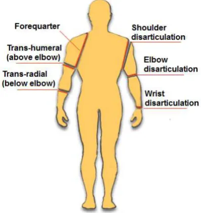
major levels of amputation, as seen in Figure 2. 8, from distal to proximal are: wrist
disarticulation, trans-radial (below elbow), elbow disarticulation, trans-humeral (above
17
Figure 2. 8: Major level of upper limb amputation (from (72)).
When the hand is completely lost, the wrist disarticulation is the most preferable level of
amputation as it preserves the supination-pronation motion of the forearm (70). However, the
resulting residual limb may not be ideal for prosthetic fitting due to its bulbous end and the
lack of room for accommodating the wrist and prosthetic hand (70). When wrist
disarticulation is impossible, trans-radial amputation is the second best choice. Trans-radial
amputation involves a cut through the forearm’s radius and ulna; preferably performed at the
junction of the distal and middle third of the forearm (70). This allows for adequate wound
healing with maintaining enough length to suspend a prosthesis and tolerate its load (70).
Although the distal radioulnar joint no longer exists at this level of amputation, some degree
of supination-pronation motion may be maintained (70).
2.6.2. Incidence of upper limb amputation
It is difficult to estimate the actual incidence of upper limb amputation worldwide since many
countries do not keep a record of the number of individuals with amputation (73). However,
the figures provided from demographic surveys/database in a few countries indicate that
individuals with major upper limb amputation represent a very small proportion relative to the
overall countries’ population (74, 75) and to the overall number of amputees (76-78). For
instance in the United States of America, of the 1.6 million amputees reported in 2005 (76),
only 41000 had a major upper limb amputation which accounts for only 8% of the amputee’s
population (76) and 0.0001% of the total USA population in 2005. In 2007, in Norway,
individuals living with major upper limb amputation accounted also for only 0.0001% of the
18
of upper limb amputees who are referred for limb fitting centres every year (77). In the most
recent dataset available, 4957 amputees were referred to limb fitting centres, and only 4.4 %
(n =218 ) of them had a major upper limb amputation (77).
From the published demographic data (74-78), trauma emerges as the main aetiology for
upper limb amputation. In the USA, 82% of upper limb amputation was caused by trauma in
2005 (76) and 84.5% in Norway in 2007 (75). In the UK, 58% of the referred upper limb
amputees acquired traumatic amputation (mostly mechanical trauma) in 2006-2007 (77). The
majority of upper limb amputees are male (75-78). Upper limb amputation is also most
commonly acquired between 16-54 years of age (75-77); a population that is likely to be at a
relatively high risk of trauma, through work or road traffic incidents.
Although the data are rather sparse, trans-radial appears to be the most common level of
amputation in most countries for which data are available. In the USA, 44% of upper limb
amputees have a trans-radial amputation in 2005, and 41% have a trans-humeral amputation
(76). Similar percentages have been reported in Norway in 2007 (trans-radial amputees
represent 43% of upper limb amputees, trans-humeral, 24% (75)). In the UK, however, 18%
and 25% of the total acquired amputees who were referred to prosthetic service were with
trans-radial and trans-humeral amputation respectively in 2007 (77).
2.7.Upper limb prostheses
All major upper limb amputations involve loss of the sensory-motor functions of the hand and
wrist joint (79). Trans-radial amputation, one of the common level of amputation, is the focus
of this thesis and here the ability to rotate the forearm is severely restricted or completely lost
if the amputation is more proximal than half the length of the forearm (69). In an attempt
restore part of the lost functions and/or body image, amputees are fitted with and trained to
use upper limb prostheses. Various models are available. Cosmetic prostheses, which provide
a passive replacement for a missing limb but offer no control mechanism are not discussed in
this thesis. The two main prosthesis types commonly used to restore function are; 1)
body-powered prostheses, i.e. prostheses that utilize movement of an anatomically intact joint to
add function, and 2) myoelectrically controlled prostheses, i.e. prostheses that utilize the
myoelectric signal from the residual musculature. In the following sections, these prosthetic
19 2.7.1. Body powered prostheses
The basic principle of body-powered prosthesis is the use of body movements to control
prosthetic components. Typically, a stainless steel Bowden cable harnessed proximally to a
stationary body segment connects distally to a prosthetic component (Figure 2. 9). When the
distal body segment that holds the prosthetic component (a prosthetic hand or split hook)
moves away from the body, the distance between the prosthetic component and the stationary
segment increases. Given that the length of the cable is fixed this causes tensional forces i n
the cable, which can be used to operate the prosthetic component in one direction (e.g.. open
or close the hand) (70). An elastic band/spring counteracts this force and returns the
component to its neutral state when the harnessed body segment returns to its neutral position.
This approach to control was first introduced in the 1920s (69) and since then, and despite
some improvements to harnessing and cable configurations, the control principle remains
unchanged (70).
Figure 2. 9: Body powered trans-radial prosthesis (adapted from (80)).
2.7.2. Myoelectric prostheses
When skeletal muscles receive a neural stimulus, a change in the polarity of the muscle fibres’
membranes takes place, resulting in action potentials (electrical activity) which cause the
muscle fibres to contract (12). This electrical activity is termed the myoelectric signal (or
electromyographic (EMG) signal). Myoelectric signals can be detected over the contracting
muscle either by invasive or surface (non-invasive) electrodes (81).
Muscle fibres in skeletal muscles are bundled in groups, and each group (so called motor unit)
20
motor units, normally small units are located deep in the muscles and large unit are
superficial. The force generated by a muscle contraction depends on both the number of motor
units recruited and their frequency of firing (81). For a low level of contraction,
predominantly deep small motor units are recruited, and for higher levels of contraction,
larger and more superficial units are recruited. The EMG signal measured by surface
electrodes represent the summation of action potentials from all active motor units and
resembles “white noise”, see Figure 2. 10.
Time [s]
A
m
p
lit
u
d
e
[µ
V
]
0.2 0.4 0.6 0.8 1 1.2 1.4 1.6 1.8 2 80
60 40 20
0 -20 -40 -60
-80
Figure 2. 10: EMG signal (adapted from (82)).
Although there has been considerable work on signal processing to extract useful information
from the EMG signals (83, 84), the more advanced techniques, such as pattern recognition,
have yet to be taken up by prosthesis manufacturers and hence are of little direct relevance to
this thesis. In the following section the methods that have been commercially adopted for
controlling myoelectric prostheses are reviewed.
As Figure 2. 10 illustrates, the amplitude of the EMG signal is very small; normally ranging
between 10 μV and 10 mV (81). In order to use the signal for control, electromagnetic
interference from the surrounding environment first needs to be filtered out, then the signal is
21
Signal rectifier Low pass filter
Amplified EMG EMG
Logic electronics Differential
amplifier
+
-Reference electrode
Rectified EMG
Smoothed EMG
Figure 2. 11: EMG signal processing for myoelectric control.
A method that amplifies the EMG signals and attenuates the noise is required. This is
achieved by using a differential amplifier. The differential amplifier amplifies the difference
between the two input signals. Since the noise is equal for both inputs, considering the
difference between the two signals allows the common noise to be eliminated. A schematic of
the differential amplifier is illustrated in Figure 2. 12.
Figure 2. 12: Schematic of a differential amplifier and surface electrodes (from (85)). Note
“n” is the noise common to both EMG signals m1 and m2.
Following amplification, full wave rectification followed by low pass filtering is used to
22
number of different control strategies are used in commercial systems and these are briefly
reviewed below.
2.7.2.1. Myoelectric control strategies
Two-site two state control strategy
The two-site two state control strategy uses electrodes mounted on two forearm sites (flexor
and extensor muscle groups) which are then processed as seen in Figure 2. 11. When the
processed myoelectric signal (PMES) from the extensor muscle group exceeds a certain
threshold the terminal device opens; when the flexor PMES exceeds a threshold then the hand
closes. However, when both electrodes detect PMESs above the assigned threshold, as in the
case of co-contraction, no action is carried out. In prosthetic devices, these thresholds are
adjusted using the gain of each differential amplifier. Using this control strategy the hand is
operated at a fixed velocity.
One-site three-state control strategy
When only one suitable muscle site is available for myoelectric control then a one-site
three-state control strategy can be used as an alternative to the more physiologically natural two-site
two-function control (81). This control method uses one of the features of the PMES obtained
from one site to control the functions of the prosthetic component (most often the prosthetic
hand). For this control strategy, two features are commonly used; the amplitude of the PMES
(level or amplitude coding) or rate of change in PMES (rate coding). Both however, provide
control over the hand state at a fixed velocity.
Control via amplitude coding uses two-threshold values, this divides the dynamic rage of the
PMES into three regions (rest, close and open) and thereby presents three control states.
When the amplitude of the PMES is below the lower threshold no action takes place with
regard to the hand state; to open the terminal device the amplitude of the PMES must exceed
the top threshold. When the PMES amplitude drops below the top threshold but is above the
lower threshold, then the terminal device automatically closes (81).
So-called rate coding employs both, the rate of change of the PMES and its amplitude for
control (81). Typically, when the mean value of the amplitude of the PMES exceeds a given
threshold, the rate of change in the amplitude of the PMES is examined to select the hand
state. Usually if the rate of change is high (as a result of fast muscle contraction), the hand
23
change is low (as a result of slow muscle contraction), the hand begins to close and keeps
closing till the PMES drops below the threshold. The main disadvantage of this control
strategy is the inherent time delay needed to calculate the rate of change of the PMES.
Proportional control strategy
A proportional control strategy enables the users to operate the prosthesis components at a
velocity proportional to the amplitude of the PMES (81). Many different techniques have
been introduced to control the speed proportionally. One technique is to employ amplitude
codingone-site three-state control, similar to what has been described above, to select the two
functions (hand opening and closing) and when the PMES is above a certain threshold, the
velocity is also controlled according to the amplitude of the PMES. Alternatively, two-site
two-state control can be used in the same fashion as described above to control the hand state,
but using the difference in the PMES amplitude of the two sites to control the velocity of the
hand.
Microprocessor controllers
Microprocessor controllers in general provide proportional speed control as the standard (86)
and also allow easy modification of the control properties without the need for hardware
adjustments. More importantly, microprocessor controllers provide a basis for more
sophisticated signal processing. For example, the Southampton hand provides secure grasping
of objects by automatically readjusting the grip force when object slippage is detected (87).
This feature is now incorporated in the “Sensorhand Speed” produced by Otto Bock (88). The
Osaka hand represents another example of an internal microprocessor controlled hand (89).
The Osaka hand provides automatic adjustment of its compliance to suit the object, thus
allowing soft objects to be grasped. The i-Limb™ Ultra hand from Touch Bionics Inc. is one
of the very recent microprocessor controlled commercially hands (90). Among the many
functional features that this hand provides is an ability to produce many different prehensile
patterns by individually motorised digits. As traditional myoelectric hands, these hands also
rely on only two muscle sites in their control in which users proportionally open and close the
hand while different prehensile patterns however are selected by the hand
microprocessor-based controller.
2.7.2.2. Myoelectric controlled prosthetic components
The first myoelectric prosthesis incorporated a simple motorised hook (81). However, the
24
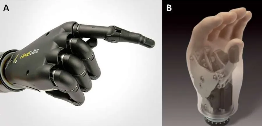
hooks (69, 81). Examples of current hands include the i-Limb™ Ultra (Figure 2. 13-A) and
Select Myo Electric hand from RSL Steeper (Figure 2. 13-B) (91). When the amputee is
expected to engage in dirty work situations or in heavy duty work, an electrically powered
hook can be provided together with a quick disconnect wrist unit to facilita te terminal device
interchanging.
Figure 2. 13: (A) i-Limb™ Ultra from Touch Bionics (from (90)), (B) Select Myo Electric
hand from RSL Steeper (from (91)).
Apart from a few very recent exceptions, such as the i-Limb Ultra from Touch Bionics Inc.,
almost all powered hands and hooks are now designed in a way that allows opposition of the
thumb against the index and middle fingers in a tripod grip (81) (one degree of freedom), or
with additional longitudinal wrist rotation (two degrees of freedom) (92, 93).
Most wrist units used with myoelectric prostheses are the same as those used with body
powered prostheses and require manual positioning (69). A powered wrist is available to the
most able user, which allows the user to control wrist rotation about the longitudinal axis of
the forearm via EMG signals. However, their function is very limited and it has been argued
that their role does not go beyond motivating the trans-radial amputee during the initial fitting
period (69, 94). The reason for this is the limited number of suitable sites on the residuum for
controlling the prosthesis, which are the same sites that are used to control the terminal device
[image:39.595.85.537.180.397.2]