http://dx.doi.org/10.4236/jsea.2013.612078
Model Analysis of Equivalence Classes in UML Events
Relations
Nazir Ahmad Zafar
Department of Computer Science, King Faisal University, Hofuf, KSA. Email: [email protected]
Received November 4th, 2013; revised November 24th, 2013; accepted December 1st, 2013
Copyright © 2013 Nazir Ahmad Zafar. This is an open access article distributed under the Creative Commons Attribution License, which permits unrestricted use, distribution, and reproduction in any medium, provided the original work is properly cited. In accor-dance of the Creative Commons Attribution License all Copyrights © 2013 are reserved for SCIRP and the owner of the intellectual property Nazir Ahmad Zafar. All Copyright © 2013 are guarded by law and by SCIRP as a guardian.
ABSTRACT
Unified Modeling Language (UML) has become a de facto standard for design, specification and modeling of object oriented software systems. UML structures being graphical in nature lack defining semantics of the systems and are prone to causing errors. Formal methods are proved to be a powerful tool for requirement analysis, design and specifi- cation of software systems. Hence, linking UML with formal approaches will enhance modeling power of software sys- tems. In this paper, an approach is developed by integrating UML and Z notation focusing on equivalence relation of the state diagrams. The Z is used because it is based on the first order predicate logic having rigorous computer tool support. The reflexivity, symmetry and transitivity properties, being important at design level, are identified and de-scribed. It is believed that this approach will be effective and useful at both academics and industrial level. The need, reasoning and benefits of the integrated approach are discussed. The resultant formal models are analyzed and validated using Z/Eves tool.
Keywords: UML; State Diagrams; Equivalence Relations; Formal Methods; Z notation; Validation and Verification
1. Introduction
Requirements analysis and design specification play an important role in software engineering. One of the ways to overcome the above issues is to describe a formal specification of the system which plays a vital role at initial phases of software engineering. Formal specifica- tion is the mathematical description that may be used to construct a consistent system in a systematic and un- ambiguous way. If formal specification of a system is described, the correctness of the required system using computer tools can easily be proved. By the use of for-mal specification, an incorrect and inconsistent design can be modified before its implementation reducing the construction cost of software systems. Formal methods which are based on discrete mathematics such as logic, set theory, graphs, can be used to describe formal de- scription ensuring quality of software. But these ap- proaches are not as welcomed at industrial level as their benefits which are observed. As software industry people do not have much mathematical background as required in real software engineering, this is one of the reasons for
ignoring use of formal methods at industrial level. How-ever, the use of formal methods is recommended for safety and security systems even by the opponent of for-mal methods.
Unified Modeling Language (UML) which is based on graphs and diagrams is much useful for requirements analysis and presenting detailed design of a system. UML, a multi-lingual graph based notation, has become a de facto standard for design and development of object oriented (OO) systems despite the fact that its semantics is still semi-formal and allows ambiguities in design of a system as in [1] and [2]. Some of the major issues in modeling using UML diagrams are: 1) UML structures are based on graphical notations and are prone to causing errors, 2) The hidden semantics of UML allows am- biguities at design level, 3) The same system needed can be described by multiple notations or diagrams which may cause inconsistencies or ambiguities and 4) UML model may have multiple interpretations and someone may not find what is put in the diagrams.
by defining semantic rules in a formal way [3]. This is because UML structures are based on graphical notations and have informal or semi-formal definitions which are prone to causing errors [4] as mentioned above. As a re- sult, there is a need for formalizing UML diagrams, par-ticularly, at design level capturing functionality of the system to be developed. This integration of formal nota-tions and UML diagrams will result in a complete, con-sistent and correct modeling approach. Z notation is a formal language used to describe and analyze the sys-tems increasing confidence at an abstract level of specifi-cation. The Z is based on first order predicate logic hav-ing rigorous computer tool support. There is a good rela-tionship between state diagram and Z notation. This is because states in state diagram can be described in terms of relationship between schemas of Z. In this paper, the relationships of the UML state diagrams are identified and transformed to Z specification. The reflexivity, sym- metry and transitivity properties of equivalence relation being important at design level are identified and de-scribed. This work is part of our ongoing project on inte-gration UML and formal methods. In this work, it de-velops a conceptual model by capturing semantics hidden under the diagrams instead of defining only syntactical mapping among the approaches. Rest of the paper is or-ganized as follows.
In Section 2, related work is discussed. Approaches used are presented in Section 3. Integration of state dia- grams and Z is given in Section 4. Model analysis is pre- sented in Section 5. Conclusion and future work are dis- cussed in Section 6.
2. Related Work
Although there exits a lot of work [5-11] on integration of approaches but there does not exists much work on linking UML diagrams with formal approaches. This is because the hidden semantics under the UML diagrams cannot be transformed easily into formal notations. It is mentioned that only closely related work is discussed in this section. For example, [12] has developed Alloy Con-straint Analyzer tool supporting the description of a sys-tem whose state space involves relational structures which are complex in nature. By the tool it is possible to analyze and develop a model by investigating the cones- quences of given constraints by an incremental approach. An approach is demonstrated using XML which is in fact a transformation tool to analyze visualize TCOZ models into various UML diagrams animating specification with a multi-paradigm programming language as discussed in [13]. In [14], it is described a way of creating tables and SQL code for Z specifications according to UML dia- grams. In another work, a relationship is investigated between Petri-nets and Z notation [15]. An integration of B and UML is presented in [16]. Formalization of the
UML is proposed by focusing on basic constructs of class structures by taking simple case studies in [17]. A tool is developed in [18] which takes UML class diagram in the form of Rational Rose petal files and evaluates it automatically and produces a list of comments on the diagrams. A comparison of UML, state-charts, Z notation, petri nets, fuzzy logic and finite state machines is pre- sented by taking a simple case study on commerce sys- tem in [19]. An approach is developed by integrating UML and Z focusing on protocols of state diagram in [20]. Some other relevant work can be found in [21-28].
3. Why UML and Formal Methods?
Designing has an important role in development process of complex systems. UML diagrams have various bene- fits for designing and modeling of systems. This is be- cause UML is a semi-formal language in which each element is strongly defined. And you are confident that it will not be misleading when you are modeling a parti- cular facet of a system. Further, UML is a concise and easy to understand language. Although UML is not a for- mal language but it has enough expressive power to han- dle massive and complex systems when viewed at an abstract level of engineering a software. It is the result of existing practices in design and modeling using object- oriented concepts, consequently, it has proved a success- ful modeling tool. Unified Modeling Language has be- come a de facto standard for designing of systems using object oriented technology [29].
On the other side, UML lacks with some important concepts and, for a moment, cannot be used for the com- plete design, specification and modeling of a system [30]. For example, UML has a lack of capturing formal se- mantics of the diagrams. Meanings are hidden under the UML diagrams which create misinterpretations and am- biguities at the implementations level. That is why link- ing and integration of UML with other languages, having expressive power of capturing semantics, is required.
The use of formal methods is motivated by a belief that appropriate mathematical analysis can contribute to the reliability and robustness of software design and spe- cification. Despite the differences over applications of formal methods the use in the development of high inte- grity safety or security systems is recommended [31]. Formal methods can be used at different levels from re-quirements engineering to maintenance of software sys-tems [32].
formal manner. At this level of applications of formal methods, proofs of properties from the specification to a program may be conducted. This way is considered as a most effective and appropriate level of applications in high integrity software systems. Furthermore, theorem proving techniques can be used to conduct formal proofs which are fully checked by machines in a systematic and ordered manner. As this is an expensive validation tech- nique, that is why, it is only applied if the cost of failure is very high. Formal methods may be classified in terms of property or model oriented [33]. Property oriented are used to describe software in terms of properties and constraints whereas model oriented are used to construct a model of a system [34]. Although there are various tools and techniques available for formal notations but at the current stage of their development in formal methods, it needs an integration of formal and traditional approa- ches.
Z is a model oriented specification language based on set theory and first order predicate logic used at an abs- tract level [35]. Z is used in this research to link with UML because of a natural relationship which exists be- tween these approaches. The Z is based upon set theory including standard set operators, comprehensions, Carte- sian products and power sets. Logic of Z is formulated using first order predicate calculus. The Z allows organi- zing a system into its components which are known as schemas and helpful at design level for managing the complex systems. The schema defines a way in which state of a system can be described and can be used for modeling the statics and dynamics of a system. A promising aspect of Z is its stepwise refinement which is verifiable and can be used from specification into an executable code.
The Z/Eves tool is used here because it is a powerful one and for analysis of Z specification [36]. It includes declaration of constants of the standard mathematical toolkit and provides useful theorem proving facility. The Eves is used to analyze schema expansion, precondition calculation, domain checking, syntax checking, type analysis, and general theorem proving mechanisms. Any specification written in a formal notation does not mean to be correct, complete and meaningful. That is why it is user responsibility to make an appropriate use of the tools for analysis insuring correctness of the model to be developed. The remarkable feature of formal specifica- tion is that it can be checked, analyzed and verified for the presence of typographical and syntactical errors by the tools. The Z/Eves provides various exploration tech- niques to prove the properties of the system.
4. Formal Model of Equivalence Classes
In this section, identification and formal analysis of ex-
isting relationships in UML state diagrams is presented. At first, approach used is discussed. Then formal defini- tions used in the model are described. Finally, statics and dynamics of the UML state diagrams are given in terms of formal models.
The integrated approach is given in this section. Al- though formal methods have a well-defined syntax and semantics but are at the early stage and, hence, it needs their integration with the existing approaches for a com- plete and consistent development of software systems. UML has become a de facto standard for design of object oriented systems. Therefore, a relationship between UML diagrams and formal techniques is analyzed and established. State diagrams are selected because of their importance for linking UML and Z notation syntactically and semantically. A mapping defining relationship be- tween these approaches is established. Initially, we have UML state diagrams which are transformed to Z notation considering both the syntax and semantics. Then rela- tionships of the state diagrams are identified to be useful in design of a system.
The state identifier and event are represented as X and E respectively both as set types. For simple specification, the basic set types are used. In the definition of a transi- tion from one state to another the guard is defined as Boolean type. A state can have two possible values that are active or passive represented by Active and Passive respectively. The type of state can be simple, non-con- current, initial or final.
In modeling using sets, we do not impose any res- triction upon the number of elements and a high level of abstraction is supposed. Further, we do not insist upon any effective procedure for deciding whether an arbitrary element is a member of the given collection or not. As a consequent, our sets X and E are sets over which we cannot define any operation. For example, cardinality to know the number of elements in a set cannot be defined. Similarly, subset and complement operations over sets X and E are not defined.
The collection of states is represented by the schema Diagram which consists of four variables that are initial, states, substates and final. The mapping substates from State to power set of State describes types of the states.
Invariants: 1) The initial state is not in the collection of states. 2) The initial state cannot be the final state. 3) The initial state does not belong to domain of substates mapping that is it has no sub-state. 4) The set of states is non-empty. 5) For any state such that it is in the domain of sub-states mapping, it is in the collection of states. 6) For any state, s, if it is in the collection of the states and is not the initial or final state and not the simple state then it belongs to domain of sub-states. 7) The final state does not belong to domain of the mapping sub-states.
To move from one state to another, a transition must be fired. The transition consists of three components that are event, guard and action. Action is in fact a sequence of events described below. The transition is defined by a schema Transition in Z which consists of three variables which are event, guard and action as given blow.
Action == seq E
The complete set of transitions of the state diagram is represented by the schema Transitions which consist of set of all possible events and the transition function de-
fined over set of states. The transition function takes a state and transition and returns the same or a new state.
Invariants: 1) For every event in the set of possible events, there must be two states and a transition over these states such that the event is in the transition and it is also included in the sequence of events called action which must be executed after the guard condition of the transition is true. 2) For any two states and a transition defined over the states, there exists an event, guard and an action such that the event is in the transition and it is also included in the sequence of events, which must be executed to move from one to the other state after the guard condition is true.
The set of events of the state diagram is represented by the schema Events which includes two schemas that are Diagram and Transitions. The Diagram represents to set of states and Transitions represent to all the possible transitions among the states as defined above. The set of events gives the relationship between the states of the state diagram and transitions among the states.
state diagram. 3) For every non-final state there is a tran- sition which acts on this state and results the same or a new state.
In the state diagram, it is possible that when a transi- tion is fired it results the same state. That means there exists a set of events over which the reflexive relation is satisfied. The reflexive relation over the set of events is defined in terms of the schema ReflexiveEvents. It takes the schema Events and verifies the above property of reflexivity.
A relation R over a set A is symmetric if for all x, y in the set A, if (x, y) is in the relation R then (y, x) is also in R. In case of state diagrams, it is possible that when a sequence of events is executed and control moves from one state S1 to another state S2 then symmetry forces and there exists an inverse of the sequence of events which results S2 to S1. The symmetric relation over the set of events of the state diagram is defined below by the schema SymmetricEvents which takes the schema Events and verifies the above symmetric property.
Invariant: 1) The events relation is symmetric over a set of states if for every sequence of events which move from S1 to S2 there exists a new sequence of events
which return S2 to S1. The sequence of events, is defined in order by event, guard and action as is the case of UML state diagrams.
Invariant: 1) For any two states s1 and s2, and a se- quence of events which move the state s1 to s2 after execution in the state diagram, for another state s3, and a sequence of events which move the state s2 to state s3, there exists another sequence of events which is con- catenation of the above sequences and it moves the state s1 to s3. The property is defined by decomposing into three parts. The first one is in which control moves from initial to next possible state. The second part is in which control moves in all possible states except initial and final state.
A relation R over A is transitive if for any x, y, z in A, and (x, y) in R and (y, z) in R the order pair (x, z) in the relation R. To define transitivity in state diagrams, if a transition is fired from one state S1 to another state S2 and then a new transition is fired from S2 to S3 then a composite transition can be fired from S1 to S3 that means the transitive relation exits over the state diagram. The formal description of transitivity over the set of events of the state diagram is defined below by using the schema TransitiveEvents which takes the above schema Events and verifies the transitive property.
To generate the set of possible collection of undoable events, a schema GenerateUndoables is described below. The schema consists of two components which are sym- metric events and a collection of undoable actions. The undoable action is one which reverses the previous action. The collection of symmetric events is given as input and set of undoable events is generated as output of the schema.
The set of accessible events can be computed by the schema GenerateAccessibles is described below. The schema consists of four components which are transitive events and a collection of accessible actions, start and target state. The collection of transitive events, start and target states are given as input and set of accessible events is generated as output of the schema.
5. Model Analysis
Since there does not exist any computer tool which may assure guarantee about the complete consistency and correctness of a computer software model. That is why we believe even the formal specification is written in any of the formal notations, it may contain potential and haz- ardous errors. Such errors may range from syntax to conceptual inconsistencies. The Z/Eves is one of the powerful tools which can be used for analyzing formal specification of a software system written in Z notation. The tool is integrated with various facilities providing rigorous analysis of the system to be developed and has automated deduction capability. Because of the abstract expressive power and model checking facilities, Z is popular among all of the formal notations and techniques, and is most widely used by the scientific community. The syntax checking, type checking and theorem proving facilities of the tool are used in this research. It is noted that syntax and type checking facilities do not require any interaction with the theorem proving facility.
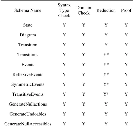
Domain checking facility of the tool allowed us to write the meaningful statements. We used Z/Eves to check the specifications for identifying the domain er- rors. It was observed that domain checking was much harder than the syntax and type checking. This is because the syntax and type checking is performed automatically whereas one has to interact with the theorem prover to perform the domain checking. We also observed that proof ‘by reduce’ in the proof window of the tool was sufficient for our formal specifications for domain checking. If the specification passes the domain checking, we get Y otherwise N as shown in Figure 1 which is a snapshot of the model analysis using Z/Eves tool.
The schema expansion facility was used to unravel the complex schemas. This facility simplified the model re- sults which were not otherwise easy to understand the detailed meaning of the given schema. Prove by reduce is one of the most important facility in the toolset and is used for analyzing the specification. The results of the model analysis are shown in Table 1. In the Table, the first column shows name of the schema analyzed and evaluated, the second column is for syntax and type check, third for domain checking, fourth for reduction facility and the last one for the proof by reduction. The symbol “*” after Y shows that proof is made by reduce- tion technique.
6. Conclusion and Future Work
Figure 1. Snapshot of the Model Analysis using Z/Eves.
Table 1. Results of Model Analysis.
Schema Name
Syntax Type Check
Domain
Check Reduction Proof
State Y Y Y Y
Diagram Y Y Y Y
Transition Y Y Y Y
Transitions Y Y Y* Y
Events Y Y Y* Y
ReflexiveEvents Y Y Y* Y
SymmetricEvents Y Y Y* Y
TransitiveEvents Y Y Y* Y
GenerateNullactions Y Y Y Y
GenerateUndoables Y Y Y Y
GenerateNullAccessibles Y Y Y Y
phical representation whereas formal methods are useful having rigorous mathematical and computer tools support for capturing the semantics hidden under the diagrams. Therefore, an integration of UML and formal methods was needed for systematic development of computer software systems. The first objective of this research was to develop an approach by linking UML to Z notation by defining a relationship among the fundamentals of UML and formal techniques. To address the reusability issue by defining the components and developing recursive approach to be useful for easing the development process was another objective.
In this paper, UML state diagrams are used to link with Z notation by identifying and formalizing the rela- tions among the states by focusing on the events and ac- tions responsible for analyzing the state diagrams. The resultant approach can be useful in development and construction of automated computer tools for generating
the specification. For linking UML with Z, most abstract view of the diagrams was perceived to define the generic formal models independent of a system which will be equally useful for any kind of domain problem.
It is mentioned that the most relevant work [37-41] was considered as starting point for this research. An exhaustive survey was done, and some interesting work was found but our work is different because of concep- tual and abstract level integration. In the existing work either example is taken to make integration or only syn- tactical mappings are defined. But we have defined both the syntax and semantic analysis of both approaches.
The Z is used because every object is assigned to a unique type providing useful programming practice. Se- veral types of checking tools exist to support the specifi- cation. The Z/Eves is a powerful tool to prove and ana- lyze the specification which was used in this research. The rich mathematical notations made it possible to rea- son about behavior of a specified system more rigorously and effectively.
REFERENCES
[1] R. Borges and A. Mota, “Integrating UML and Formal Methods”, Electronic Notes in Theoretical Computer
Science, Vol. 184, 2003, pp. 97-112.
http://dx.doi.org/10.1016/j.entcs.2007.03.017
[2] W. L. Yeung, K. R. P. H. Leung, J. Wang and W. Dong, “Improvements towards Formalizing UML State Diag- rams in CSP,” Proceedings of 12th Asia Pacific Software
Engineering Conference, Taiwan, 2005, p. 7.
http://dx.doi.org/10.1109/APSEC.2005.70
[3] M. Shroff and R. B. France, “Towards Formalization of UML Class Structures in Z,” 21st International Conferen-
ce on Computer Software and Applications, Washington,
DC, 1997, pp. 646-651.
[4] A. M. Mostafa, A. I. Manal, E. B. Hatem and E. M. Saad, “Toward a Formalization of UML2.0 Meta-model using Z Specifications,” Proceedings of 8th ACIS International
Conference on Software Engineering, Artificial Intelli-
gence, Networking and Parallel/Distributed Computing,
Qingdao, Vol. 3, 2007, pp. 694-701.
[5] B. Akbarpour, S. Tahar and A. Dekdouk, “Formalization of Cadence SPW Fixed-Point Arithmetic in HOL,” For-
mal Methods in System Design, Vol. 27, No. 1-2, 2005,
pp. 173-200.
http://dx.doi.org/10.1007/s10703-005-2256-8
[6] K. Araki, A. Galloway and K. Taguchi, “Using Process Algebra to Control B Operations,” Proceedings of 1st
International Conference on Integrated Formal Methods,
London, 1999, pp. 437-456.
[7] H. Beek, A. Fantechi, S. Gnesi and F. Mazzanti, “State/ Event-Based Software Model Checking,” Proceedings of
4th International Conference on Integrated Formal
Methods, Canterbury, Vol. 2999, 2004, pp. 128-147.
[image:7.595.56.285.284.504.2]national Conference on Integrated Formal Methods, Lon- don, Vol. 1945, 2000, pp. 194-213.
http://dx.doi.org/10.1007/3-540-40911-4_12
[9] F. Gervais, M. Frappier and R. Laleau, “Synthesizing B Specifications from EB3 Attribute Definitions,” Proceed-
ings of 5th International Conference on Integrated For-
mal Methods, Berlin/Heidelberg, Vol. 3771, 2005, pp.
207-226. http://dx.doi.org/10.1007/11589976_13
[10] O. Hasan and S. Tahar, “Verification of Probabilistic Properties in the HOL Theorem Prover,” Proceedings of
the Integrated Formal Methods, Oxford, Vol. 4591, 2007,
pp. 333-352.
http://dx.doi.org/10.1007/978-3-540-73210-5_18
[11] T. B. Raymond, “Integrating Formal Methods by Unify- ing Abstractions,” Vol. 2999, 2004, pp. 441-460.
[12] D. Jackson, I. Schechter and I. Shlyakhter, “Alcoa: The Alloy Constraint Analyzer,” Proceedings of International
Conference on Software Engineering, Limerick, 2000, pp.
730-733.
[13] J. Sun, J. S. Dong, J. Liu and H. Wang, “A XML/XSL Approach to Visualize and Animate TCOZ,” Proceedings
of 8th Asia-Pacific Software Engineering Conference,
Macao, 2001, pp. 453-460.
[14] A. Moeini and R. O. Mesbah, “Specification and Deve- lopment of Database Applications based on Z and SQL,”
Proceedings of 2009 International Conference on Infor-
mation Management and Engineering, Kuala 2009, pp.
399-405.
[15] M. Heiner and M. Heisel, “Modeling Safety Critical Systems with Z and Petri-Nets,” Proceedings of Interna-
tional Conference on Computer Safety, Reliability and
Security, London, 1999, pp. 361-374.
http://dx.doi.org/10.1007/3-540-48249-0_31
[16] H. Leading and J. Souquieres, “Integration of UML and B Specification Techniques: Systematic Transformation from OCL Expressions into B,” Proceedings of 9th Asia-
Pacific Software Engineering Conference, Gold Coast,
2002, p. 495.
[17] Z. M. Ma, “Fuzzy Conceptual Information Modeling in UML Data Model,” International Symposium on Com-
puter Science and Computational Technology, Shanghai,
2008, pp. 331-334.
http://dx.doi.org/10.1109/ISCSCT.2008.353
[18] N. H. Ali, Z. Shukur and S. Idris, “A Design of an Asses- sment System for UML Class Diagram,” International
Conference on Computational Science and Applications,
Kuala Lampur, 2007, pp. 539-546.
[19] S. A. Ehikioya and B. Ola, “A Comparison of Formalisms for Electronic Commerce Systems,’ Proceedings of Inter-
national Conference on Computational Cybernetics, Vie-
nna, 2004, pp. 253-258.
[20] F. Alhumaidan, “State Based Static and Dynamic Formal Analysis of UML State Diagrams,” Journal of Software
Engineering and Applications, Vol. 5 No. 7, 2012, pp.
483-491. http://dx.doi.org/10.4236/jsea.2012.57056
[21] Zafar, N. A. “LR(K) Parser Construction Using Bottom- up Formal Analysis,” Journal of Software Engineering
and Applications, Vol. 5, No. 1, 2012, pp. 21-28.
http://dx.doi.org/10.4236/jsea.2012.51004
[22] Liu and C. Chen, “An Improved Quasi-Static Scheduling Algorithm for Mixed Data-Control Embedded Software,”
Journal of Applied Sciences, Vol. 6, 2006, pp. 1571-1575.
http://dx.doi.org/10.3923/jas.2006.1571.1575
[23] N. A. Zafar and F. Alsaade, “Syntax-Tree Regular Expre- ssion Based DFA Formal Construction,” Intelligent Infor-
mation Management (IIM), Vol. 4, No. 4, 2012, pp. 138-
146. http://dx.doi.org/10.4236/iim.2012.44021
[24] N. A. Zafar, A. Hussain and A. Ali, “Verifying Monoid and Group Morphisms over Strongly Connected Alge- braic Automata,” Journal of Software Engineering and
Applications, Vol. 3, No. 8, 2010, pp. 803-812.
http://dx.doi.org/10.4236/jsea.2010.38093
[25] N. A. Zafar, N. Sabir and A. Ali, “Construction of Inter- section of Nondeterministic Finite Automata using Z Notation,” International Journal of Electrical and Com-
puter Engineering, Vol. 3, No. 2, 2008, pp. 96-101.
[26] N. A. Zafar, “Formal Specification and Validation of Railway Network Components Using Z Notation,” IET,
Software, Vol. 3, No. 4, 2009, pp. 312-320.
http://dx.doi.org/10.1049/iet-sen.2008.0082
[27] N. A. Zafar, A. Hussain and A. Ali, “Refinement: Formal Proof of Equivalence in Endomorphisms and Automor- phisms over Strongly Connected Automata,” Journal of
Software Engineering and Applications, Vol. 2, No. 2,
2009, pp. 77-85.
http://dx.doi.org/10.4236/jsea.2009.22012
[28] Z. Derakhshandeh, B. T. Ladani and N. Nematbakhsh, “Modeling and Combining Access Control Policies Using Constrained Policy Graph (CPG),” Journal of Applied
Sciences, Vol. 8, No. 20, 2008, pp. 3561-3571.
http://dx.doi.org/10.3923/jas.2008.3561.3571
[29] X. Than, H. Miao and L. Liu, “Formalizing Semantics of UML Statecharts with Z,” Proceedings of 4th Interna- tional Conference on Computer & Information Techno- logy, Wuhan, 2004, pp. 1116-1121.
[30] S. Sengupta and S. Bhattacharya, “Formalization of UML Diagrams and Consistency Verification: A Z Notation Based Approach,” Proceedings of India Software Engi-
neering Conference, 2008, pp. 151-152.
[31] M. L. Shahreza, B. A. L. Gwandu and D. J. Creasey, “Im- portance of Formal Specification in Design of Hardware Systems,” IEE Colloquium on Structured Methods for
Hardware Systems Design, London, 1994, pp. 1-3.
[32] A. Hall, “Correctness by Construction: Integrating For- mality into a Commercial Development Process,” Pro- ceedings of International Symposium of Formal Methods
Europe, Copenhagen, Vol. 2391, 2002, pp. 139-157.
[33] M. Brendan and J. S. Dong, “Blending Object-Z and Timed CSP: An Introduction to TCOZ,” Proceedings of
International Conference on Software Engineering, Kyo-
to, 1998, pp. 95-104.
[34] J. M. Spivey, “The Z Notation: A Reference Manual,” Englewood Cliffs NJ, Prentice-Hall, 1989.
[36] S. Zarina, N. Alias, M. M. Halip and B. Idrus, “Formal Specification and Validation of Selective Acknowledge- ment Protocol Using Z/EVES Theorem Prover,” Journal
of Applied Sciences, Vol. 6, No. 8, 2006, pp. 1712-1719.
http://dx.doi.org/10.3923/jas.2006.1712.1719
[37] H. Miao, L. Liu and L. Li, “Formalizing UML Models with Object-Z,” Proceedings of 4th International Confe-
rence on Formal Methods and Software Engineering,
London, Vol. 2495, 2002, pp. 523-534. http://dx.doi.org/10.1007/3-540-36103-0_53
[38] N. A. Zafar and F. Alhumaidan, “Transformation of Class Diagrams into Formal Specification,” International Jour-
nal of Computer Science and Network Security, Vol. 11,
No. 5, 2011, pp. 289-295.
[39] S. A. Vilkomir and J. P. Bowen, “Formalization of Soft- ware Testing Criterion using Z Notation,” 25th Annual
International Computer Software and Applications, Chi-
cago, 2001, pp. 351-356.
[40] X. He, “Formalizing UML Class Diagrams: A Hierar- chical Predicate Transition Net Approach,” Proceedings of Twenty-Fourth Annual International Computer Soft-
ware and Applications Conference, Taipei, 2000, pp. 217-
222.
[41] N. A. Zafar, N. Sabir and A. Ali, “Formal Transformation from NFA to Z Notation by Constructing Union of Regu- lar Languages,” International Journal of Mathematical
Models and Methods in Applied Sciences, Vol. 3, No. 2,