Inline Measurements: A Native Measurement
Technique for IPv6 Networks
D. P. Pezaros
1,
Member, IEEE,
D. Hutchison
1,
Member, IEEE,
R. D. Gardner
2,
Member, IEEE
, F. J.
Garcia
2, J. S. Sventek
3,
Member, IEEE
1Computing Department, Lancaster University, Lancaster, LA1 4YR, UK. 2Agilent Laboratories Scotland, Agilent Technologies, Edinburgh, EH30 9TG, UK.
3Networked Systems Measurement & Control Group, Computing Science Dept., Univ. of Glasgow, Glasgow, G12 8QQ, UK.
E-mail: {dp, dh}@comp.lancs.ac.uk, {frankie_garcia, robert_gardner}@agilent.com, [email protected]
Abstract – Next generation convergence networks require ubiquitous measurement mechanisms able to dynamically assess the performance quality characteristics experienced by the different, aggregated traffic flows traversing end-to-end Internet paths. Existing service measurements fall into two main categories: active and passive. This paper introduces a complementary technique called ‘inline measurements’ that makes use of the extendible features of the emerging IPv6 pro-tocol. Through the exploitation of native IPv6 extension head-ers, measurement triggers and minimal measurement data may be carried in the same packets as the payload data itself, providing a high level of probability that the behaviour of the real user traffic flow is being observed. By adding measure-ment functionality natively, at the network (IPv6) layer, inline measurements can potentially target all transport and applica-tion services, providing an accurate performance evaluaapplica-tion framework for next generation networks. The paper also pre-sents the results from a dynamically configurable prototype implementation in which end-to-end, one-way delay and delay variation of real-time video streams have been measured.
Index Terms – active, passive, measurement, monitoring, performance, quality of service, service management, IPv6, extension headers, delay measurement, real-time traffic.
I. INTRODUCTION
The Internet Protocol (IP) is emerging as the ubiquitous, universal convergence layer in the gradual marriage of te-lephony networks with data communications networks. The result is the increasing aggregation of multi-service traffic on IP networks that operate, by nature, according to the ‘best-effort’ paradigm.
Within this environment supplementary mechanisms are required to ensure the IP network is able to deliver the ap-propriate quality of service (QoS). This is particularly im-portant for high revenue generating, time-critical data flows, such as voice calls [1, 2, 3].
Various QoS techniques are being developed, such as DiffServ [4] and IntServ/RSVP [5] or overlay models in-volving MPLS, ATM and Frame Relay, which are able to provide a range of QoS levels that can be categorised in terms of synchronicity, latency, jitter, loss and throughput. However, key to the success of delivering good quality of service is the ability to measure and monitor the service
performance provided by the network and provide appro-priate, timely feedback to maintain QoS levels.
At the lower layers, measurement and monitoring allow network operators to gauge the real-time health of the net-work through, for example, detecting traffic congestion and delay, measuring throughput, checking link / path availabil-ity, verifying routing/forwarding mechanisms and calculat-ing error rates. Measurement and monitorcalculat-ing enable respon-sive traffic engineering, providing a path towards auto-mated provisioning and optimisation within the network.
At the service layer, network service providers use measurement and monitoring to check if service level agreements are being met, to monitor individual end-user service quality, to provide billing, policing and fraud detec-tion, to determine traffic levels for short and longer term provisioning and thus avoid the expense of over-provisioning.
QoS measurement techniques fall under two main cate-gories: active and passive [6, 7]. Active measurements are performed by injecting traffic with known characteristics into the network at one point and observing the same traffic at another point and are often used to test specific attributes of a service, such as available bandwidth and one-way de-lay. On the other hand, passive measurements involve ob-serving real traffic on a link without disruption to the ser-vice, often employing filtering and event search mecha-nisms to continuously maintain and update attribute count-ers. Passive measurements are commonly used for one-point packet filtering and counting measurements. Figure 1 shows a general measurement structure that may apply to network management, in which active or passive measure-ments may be performed, together with feedback to control the network and adapt the incoming traffic.
Traffic
Control Actuators
MEASURED SYSTEM
Measurem ent & Control Application
Sensors
External System s
INPUTS OUTPUTS
[image:2.612.57.292.70.198.2]Measurem ent
Figure 1: General System Measurement Structure
The term ‘inline’ implies that measurement invoking triggers and the measurement data are piggybacked onto real user packets using the extendible features of IPv6. Hav-ing potentially low overhead and minor impact on the net-work traffic, this service-oriented technique measures, with a high level of probability, the real user experience and it is equally applicable to measuring certain aspects of aggregate flows as it is to particular applications or protocols.
This paper is organised as follows: Section II presents the IPv6 inline measurement technique, outlines various strengths and weaknesses compared to alternative ap-proaches and discusses appropriate application areas. Sec-tion III describes one-way delay measurements carried out using IPv6 inline measurements. Section IV concludes the paper, describing some future work that is intended in this area.
II. INLINE MEASUREMENTS
A. General description of the technique
[image:2.612.320.556.316.527.2]The inline measurement technique requires that meas-urement data and triggering mechanisms be piggybacked onto real user packets and it may be viewed in part as a hybrid of active and passive measurement approaches – see Figure 2.
Measurement trigger and/or data added
Hdr Payload
Measurement is triggered and/or data removed
Figure 2: Inline Measurement Technique
Inline measurements are intrinsically multi-point meas-urements whereby packets are tagged with information at one point in the network and this information is augmented, retrieved and/or observed at a point or points elsewhere. As a result, the complex task of correlating measurements from multiple points in the network is circumvented, as it is
en-tirely certain that the same packet has been observed at any chosen point in the network.
Similarly, because any added measurement data will be piggybacked onto real user traffic, it will, with a high de-gree of probability, receive the same treatment and follow the same path as the real user traffic. Thus an accurate re-flection of the characteristics of the real user traffic flows can be obtained, provided that the marginal change to se-lected packets does not adversely affect the overall packet flow. There is also a small additional systematic processing delay. These issues are detailed in subsection C.
B. Implementation via IPv6 Extension Headers
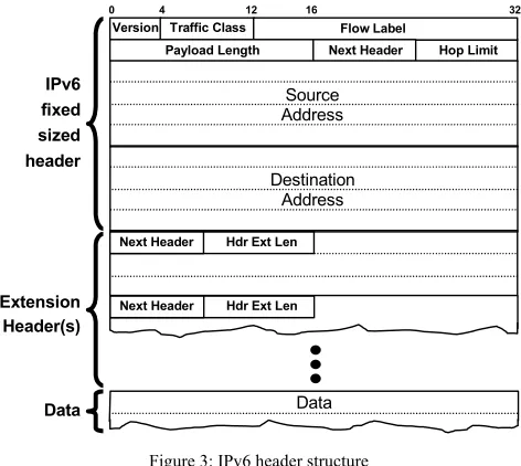
Native Internet Protocol version 6 (IPv6) extension head-ers [8] can be conveniently used to implement inline meas-urements. IPv6 has a common, 40-octet, fixed-sized header that holds the addresses and potential QoS capability – see Figure 3. Data for other functionality is implemented via a daisy-chain of optional extension headers positioned before the payload some of which hold small data structures called ‘options’.
0 4 12 16 32
Version Traffic Class Flow Label
Payload Length Next Header Hop Limit
Next Header Hdr Ext Len IPv6
fixed sized header
Extension Header(s)
Data
Source Address
Destination Address
Hdr Ext Len Next Header
Data
Figure 3: IPv6 header structure
In contrast to IPv4, IPv6 extension headers and their op-tions are only processed where necessary in the network and there are specific rules relating to the order in which they must be processed. The IPv6 standard defines a small number of extension headers such as Hop-By-Hop Options, Destination Options, Routing, Fragment, Authentication and Encapsulating Security Payload. However, other exten-sion headers and options can be defined for dedicated pur-poses – e.g. those within recent Mobile IPv6 IETF drafts.
[image:2.612.53.295.516.622.2]its predecessor, IPv4, of being able to encode optional func-tionality mechanisms natively, without influencing the core of the forwarding mechanism.
The lack of need for option processing en-route elimi-nates the concerns of instrumented traffic being treated dif-ferently in routers than the rest of the traffic (e.g. fast/slow path, different processing queues). Also, the flexibility of processing extension headers only at specified nodes re-duces the need for lengthy standardisation processes; in-cremental deployment is facilitated by the encoding of the extension headers that specifies the action to be taken when a node does not support a particular option. Last but not least, the flexibility of defining new, variable length options allows for testing and experimentation, as well as for addi-tional funcaddi-tionality to be implemented at the ubiquitous network (IPv6) layer.
In this work, it is proposed that the Destination Options extension header be used to carry additional, bespoke op-tions to convey measurement data such as timestamps, counters, trace information or other associated measure-ment system traffic. The Destination Options extension header is used to encapsulate standalone options in a Type-Length-Value (TLV) format, to be processed by a packet’s destination and is thus ideal for performing end-to-end inline service measurements. The Destination Options ex-tension header is illustrated in Figure 4.
Next Header Hdr Ext Len
Options
TLV-encoded Options
Next Header Hdr Ext Len
(1 octet) (1 octet)
[image:3.612.55.296.390.447.2](variable number of octets)
Figure 4: Destination options extension header
The next header field contains a code identifying the sub-sequent header or higher-layer protocol payload type. The Hdr Ext Len field holds the length, in octets, of destination options header excluding the Next Header Field. The op-tions field is of variable length and contains TLV-encoded destination options, which represent a suitable format for the transportation of opaque objects – see Figure 5. Options also have a type and a length. They are processed in se-quence and, by setting bits in the type field, may be skipped or an error issued if unrecognised by a processing entity.
O ption Type O ption Length D ata
1 octet 1 octet varia ble num ber of octets
Figure 5: TLV-encoded option structure
Using a combination of destination options and appropri-ate measurement infrastructure, it is possible to selectively add data to real user traffic, which can be detected and processed elsewhere in the network making use of the IPv6 stack. The level of processing will be determined by the
options carried and may involve operations such as incre-menting counters, adding timestamp annotations, extracting and caching packet data. Note that with the addition of a routing header, it would even be possible to target specific ‘destinations’ en-route to enable the implementation of more detailed service measurements as the user traffic crosses pertinent points.
A particularly elegant approach to inline measurement implementation is to use fixed or temporary extensions to the existing IPv6 protocol stack, the approach used to pro-duce results for this paper. Temporary extensions can be achieved using dynamically loadable modules with appro-priate hooks in the kernel stack, allowing the extension header processing rules defined within the IPv6 standard to be maintained. Alternatively, packets could be suitably in-strumented and observed via separate hardware/firmware elements that may exist inside interface cards or just out-side, attached as a separate plug-in module. A full descrip-tion of implementadescrip-tion methods including a discussion on appropriate programmable networking techniques is outside the scope of this paper.
C. Comparison with other techniques
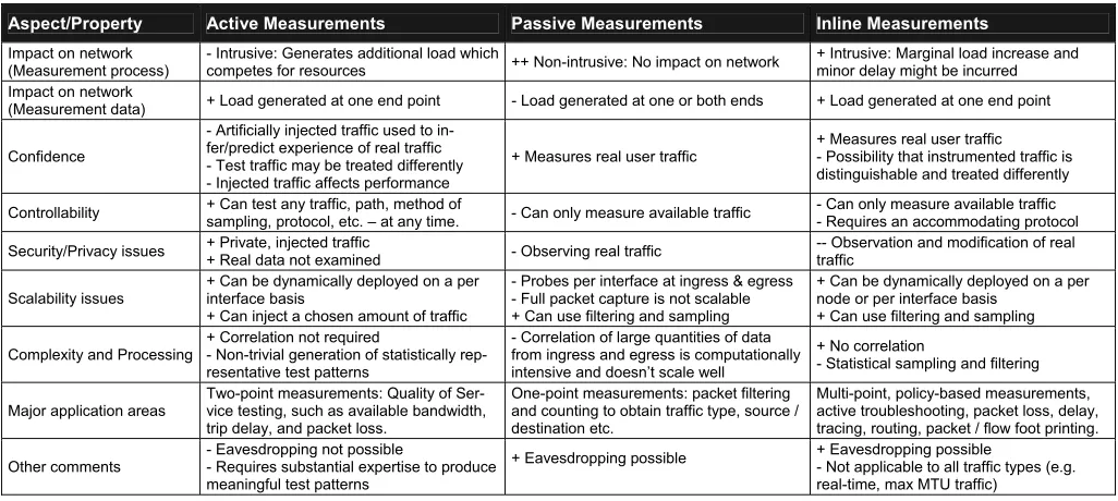
The inline measurement technique has benefits and drawbacks and it should thus be considered as another po-tentially useful approach to measurement that may com-plement existing solutions. Just like the active and passive measurement approaches, they are not applicable for every type of measurement. A comparison of inline, active and passive measurement techniques is given in Table 1, in which ‘+’ / ‘-’ represent perceived advantages / disadvan-tages respectively.
The main advantages of inline measurements are minimal additional load on the network, ability to measure the ‘real user experience’, two-point measurement capability without requirement for data shipping and correlation, the ability to perform policy-based measurements on a dynamically de-ployable basis, and a suitably wide variety of measurement application areas. The main disadvantages of inline meas-urements are their intrusive nature, requirement for an ac-commodating protocol, security and privacy concerns since some packets must be modified, and that they can only op-erate when there is traffic available.
[image:3.612.59.288.601.635.2]A particular concern with active measurements is that performance properties measured by active techniques do not necessarily reflect the behaviour experienced by opera-tional network traffic since synthetic traffic may not have exactly the same statistical properties and may be treated differently if too easily distinguishable. The additional traf-fic unavoidably impacts the network and may itself be a factor in measuring a poorer performance than the network would otherwise deliver. Also, periodic sampling and packet injection used by some techniques may fail to ob-serve periodic network events [9].
D. Appropriate application areas
Inline measurements are well-suited to end-to-end, two-point and multi-two-point measurements such as packet tracing, one-way and round-trip delay, and path loss. For example, tagging various types of signalling traffic may facilitate service level agreement verification and/or application troubleshooting.
Moreover, the same inline measurement framework can perform passive type one-point measurements that involve filtering and classifying passing packet flows and maintain-ing various attribute counts, particularly useful for network performance monitoring and troubleshooting.
Adopting a more active approach, inline measurements lend themselves well to policy-based, event—condition— action operations, where the occurrence of certain packets triggers measurement or other network management activ-ity, such as billing and accounting functions.
III. ONE-WAY DELAY MEASUREMENT
To demonstrate the feasibility and applicability of the inline measurement technique, various measurement ex-periments have been performed on different traffic types carried over a variety of operational IPv6 networks [10].
[image:4.612.321.552.132.270.2]Owing to space limitations, this paper describes only one such scenario: measurement of one-way delay and jitter for streamed UDP video traffic across relatively low-capacity wireless and ADSL IPv6 measurement test beds at Lancas-ter University – see Figure 6.
Figure 6: Lancaster University Measurement Test bed
A. Framework Overview
With a strong bias to placing intelligence in networking nodes where and when required, programmable networking concepts [11, 12] have been utilised to develop a prototype system at Agilent Laboratories. Underpinning the design philosophy is the notion of telemetry modules which are the basic components that instrument nodes to facilitate inline measurement techniques through the addition, modification and removal of data in the extension headers, as well as other supporting functions such as the storage, retrieval, correlation and forwarding of measurement-related data. These modules can be dynamically created and remotely configured, managed and controlled. A more detailed de-scription of the measurement framework is outside the scope of this paper
TABLE 1: SUMMARY OF BENEFITS AND DRAWBACKS OF PASSIVE, ACTIVE AND INLINE MEASUREMENT TECHNIQUES
Aspect/Property Active Measurements Passive Measurements Inline Measurements
Impact on network
(Measurement process) - Intrusive: Generates additional load which competes for resources ++ Non-intrusive: No impact on network + Intrusive: Marginal load increase and minor delay might be incurred Impact on network
(Measurement data) + Load generated at one end point - Load generated at one or both ends + Load generated at one end point
Confidence
- Artificially injected traffic used to in-fer/predict experience of real traffic - Test traffic may be treated differently - Injected traffic affects performance
+ Measures real user traffic + Measures real user traffic - Possibility that instrumented traffic is distinguishable and treated differently
Controllability + Can test any traffic, path, method of sampling, protocol, etc. – at any time. - Can only measure available traffic - Can only measure available traffic - Requires an accommodating protocol
Security/Privacy issues + Private, injected traffic
+ Real data not examined - Observing real traffic
-- Observation and modification of real traffic
Scalability issues + Can be dynamically deployed on a per interface basis + Can inject a chosen amount of traffic
- Probes per interface at ingress & egress - Full packet capture is not scalable + Can use filtering and sampling
+ Can be dynamically deployed on a per node or per interface basis
+ Can use filtering and sampling
Complexity and Processing + Correlation not required - Non-trivial generation of statistically rep-resentative test patterns
- Correlation of large quantities of data from ingress and egress is computationally intensive and doesn’t scale well
+ No correlation
- Statistical sampling and filtering
Major application areas Two-point measurements: Quality of Ser-vice testing, such as available bandwidth, trip delay, and packet loss.
One-point measurements: packet filtering and counting to obtain traffic type, source / destination etc.
Multi-point, policy-based measurements, active troubleshooting, packet loss, delay, tracing, routing, packet / flow foot printing.
Other comments - Eavesdropping not possible - Requires substantial expertise to produce meaningful test patterns
[image:4.612.54.567.501.731.2]B. One-way Delay Telemetry Module
A one-way delay measurement typically requires that at least two different telemetry modules be operating simulta-neously. On loading, each module hooks into the Linux kernel protocol stack, allowing packets to be modified as required. Figure 7 shows the typical operation of the one-way delay modules at a source and destination node of a measured path.
2. Create Ext Hdr 3. Add Timestamp 4. Insert Ext Hdr 1. Select Packet
1. Filter 2. Add Timestamp 3. Add to output message queue
One way delay source
module One way delay destination module
To user space Configuration
from user space
[image:5.612.319.557.176.292.2]Packet Flow Options carried in packets to destination
Figure 7: One-way delay source and destination modules
The source module selects a packet based on the filter and sampling criteria that were uploaded to the module in advance. Subsequently a 22-octet ‘one-way delay option’ (see Figure 8) is generated, timestamped and appended to the existing or a newly created destination options header. The destination module looks for appropriately instru-mented IPv6 packets and adds the second time-stamp. The data in the IPv6, extension and transport layer headers then join a FIFO message queue, accessible from user space. If required, the extension header/option may be stripped from the packet returning the packet to its original form.
Source timestamp: seconds
Option data len Option type
Overflow
Pointer Flags (Reserved)
Source timestamp: microseconds Destination timestamp: seconds Destination timestamp: microseconds
4 octets (Total option size: 22 octets)
[image:5.612.54.296.181.264.2]Figure 8: One-way delay TLV-encoded option
Source and destination points are clock synchronised us-ing an NTP or a GPS clock feed, dependus-ing on the degree of accuracy required. The open-source VideoLAN [13] server/client pair was used to stream MPEG video traffic between the different nodes in the test bed across wireless (IEEE 802.11b) and ADSL links of interest. In the genera-tion of all the following results, no packet sampling was performed and the filter was configured to instrument UDP packets only.
C. Measurement Results
Inline measurements were used successfully to measure the one-way delay and jitter of a UDP video stream across the testbed and operational networks. The one-way delay of packets was calculated as the difference between the source
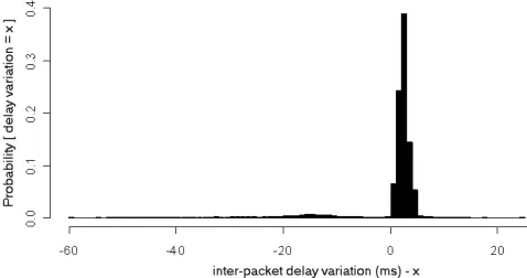
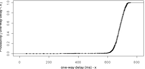
[image:5.612.317.556.324.450.2]and destination timestamps recorded in the one-way delay options of each packet. Jitter was calculated as the differ-ence between the one-way delays of consecutive packets, i.e. the Inter-Packet Delay Variation (IPDV), as defined in a draft of the IETF IPPM working group. Figures 9 and 10 show the distribution of one-way delay and a histogram of the jitter, respectively, measured for a video stream over the wireless IPv6 configurations.
Figure 9: One-way delay (ms) of video stream over the wireless networks
Figure 10: IPDV of video stream over the wireless networks
The instantaneous one-way delay for this video stream assumes values from 6 to 76 ms maintaining a mean of 19.15 ms. The Inter-Packet Delay Variation (jitter) mostly takes positive values close to zero, implying that jitter is kept at low levels and the delays in video stream tend to slightly increase. However some bursts of sudden decreases in successive delays can also be seen that reached the val-ues up to around (negative) 60 ms.
Figures 11 and 12 represent a set of more interesting measurement cases conducted over the lower-capacity ADSL networks. Traffic spanned higher-contention opera-tional ISP topologies, and apart from the significantly higher delay values, greater fluctuations in the successive delay indications were also observed. One-way delay as-sumes values between 46 and 756 ms and the mean delay was 680 ms. Jitter varies from decreases of up to 144 ms to increases up to 78 ms, with significant peaks at relatively high values.
[image:5.612.71.278.428.500.2]The design of a prototype implementation has been briefly described, showing how the technique can be provi-sionally realised and exploited to measure one-way delay of a real-time UDP video stream operating over both wired and wireless IPv6 topologies.
results. The one-way delay always assumed values between 1 and 2 ms and the jitter varied between -1 and 1 ms.
22 octets of overhead were appended to each UDP/IP packet of original length 1326 octets, representing an over-all efficiency of 98.4%, a figure that could be substantiover-ally improved using packet sampling. For example, sampling 1 in 20 packets would give 99.9% efficiency, but the certainty of the results would be correspondingly poorer.
Further work will concentrate on exploiting filtering and sampling mechanisms to address scalability and overhead issues while assessing the applicability of inline measure-ments for particular application domains and network op-erations such as mobility management.
ACKNOWLEDGEMENTS
We are grateful to Agilent Technologies for the support of Dimitris Pezaros’ work through an industrial fellowship. We also thank Theodore Kypraios from the Department of Mathematics and Statistics, Lancaster University, for his valuable comments on the presentation of the results.
REFERENCES
[1] H. G. Hegering, S. Abeck, B. Neumair, “Integrated Man-agement of Networked Systems”, Kaufmann, 1998.
Figure 11: One-way delay (ms) of video stream over the ADSL links
[2] V. Paxson, “Towards a Framework for Defining Internet Performance Metrics”, Proceedings of INET’96, Montreal, Canada, June 1996.
[3] K. Claffy, H. Braun, G. Polyzos, “A Parameterizable Meth-odology For Internet Traffic Flow Profiling”, IEEE JSAC, Special Issue on the Global Internet, 1995.
[4] S. Blake, D. Black, M. Carlson, E. Davies, Z. Wang and W. Weiss, “An Architecture for Differentiated Services”, RFC 2475, December 1998.
[5] R. Braden, D. Clark and S. Shenker “Integrated Services in the Internet Architecture: an Overview”, RFC 1633, June 1994.
[image:6.612.57.295.180.294.2][6] C. Fraleigh, et. al., “Design and Deployment of a Passive Monitoring Infrastructure”, Passive and Active Measurement Workshop (PAM2001), Amsterdam, April 2001.
Figure 12: IPDV of a video stream over the ADSL links
[7] Georgatos, F. Gruber, et. al., “Providing Active Measure-ments as a Regular Service for ISP's”, Passive and Active Measurement Workshop (PAM2001), Amsterdam, April 2001.
It is worth mentioning that the measurements take into account clock drifts in each system from the appropriate NTP server. While running, NTP improves the clock’s ac-curacy, and as the NTP polling intervals increase (i.e. from the default values of 64 to 1024 s), the clock drifts tend towards a fairly static and stable value.
[8] S. Deering, R. Hinden, “Internet Protocol Version 6 (IPv6) Specification”, RFC 2460, December 1998.
[9] W. Matthews, L. Cottrell, “The PingER project: Active Inter-net Performance Monitoring for the HENP Community”,
IEEE Communications Magazine, May 2000 IV. CONCLUSIONS AND FUTURE WORK
[10] Pezaros, D.,P., Hutchison, D., Garcia, F.,J., Gardner, R., Sventek, J.,S., “Service Quality Measurements for IPv6 Inter-networks”, to appear in International Workshop on Quality of Service (IWQoS), Montreal, Canada, June 7-9, 2004
This paper introduced and demonstrated an inline meas-urement technique for assessing the performance properties of application flows across the Internet. This measurement approach exploits the concept of IPv6 extension headers to instrument portions of the network traffic, thus giving high probability that the measurements reflect the service ex-perienced by real user data. Indeed, the technique could conceivably be integrated into the IPv6 stack as standard. The characteristics of inline measurements and the relative benefits and drawbacks over traditional measurement tech-niques have been discussed, and the scenarios and assump-tions under which inline measurements should operate have also been highlighted.
[11] Francisco J. Garcia, “Programmability Support for Service Monitoring”, Programmable Networks 2003 (Prognet 03), Brighton, December 2003.
[12] M. Fry and A. Ghosh, “Application level active networking”,
Computer Networks, 31 (7), pp.655-667, 1999.