Technology (IJRASET)
Comparison of Power Quality Improvement
by D-STATCOM and Distributed
Generation in Distribution System
G.Saritha1, Dr.Chandrashekhar Reddy.S2
Sr.Asst.Professor1, Professor2
Department of EEE, Christu Jyothi Institute of Technology & Science, Jangaon, Warangal-506167-T.S
Abstract— In t his p a p e r proposes operation and control of converter b a s e d single phase distributed generators (DG) in a utility connected grid. A common utility practice is to distribute the household single-phase loads evenly between the three phases. The voltage unbalance between the phases remains within a reasonable limit. However the voltage unbalance can be severe if single-phase rooftop mounted PVs are distributed randomly between the households. Moreover, there can also be single phase non-linear loads present in the system. The cumulative effect of all these will cause power quality problems at utility side. The problem can be macabre if three-phase active loads (e.g., induction motors) are connected to utility feeder. To counteract this problem, first scheme a distribution static compensator (DSTATCOM) is connected at the utility bus to improve the power quality. The DSTATCOM only supplies reactive power and no real power. In the second scheme, a larger three-phase converter controlled DG is placed that not only supplies the reactive power but also provides active power. The efficacies of the controllers have been validated through simulation for various operating conditions using MATLAB.
Keywords— DSTATCOM, DG, Power Quality, MATLAB, Simulink.
I. INTRODUCTION
As more countries are aiming at a reduction in greenhouse gas emissions, the requirements for adding new generation capacity can no longer be met by traditional power Generation methods of burning the primary fossil fuels such as coal, oil, natural gas, etc.. This is why distributed generators (DG) have significant opportunity in the evolving power system network. Both consumers and power utilities can benefit from the widespread deployment of DG systems which offer secure and diversified energy options, increase generation and transmission e f f i c i e n c y , reduce g r e e n h o u s e gas emissions, improve power quality and system stability, cut energy costs and capital expenditures, and alleviate the bottleneck caused by distribution lines. Properly sited DG can increase the feeder capacity limit, but this does not necessarily produce an improvement in system reliability o r p o w e r q u a l i t y , a s quantified by standard indices. With improving reliability of the owner, the DG may reduce the severity of voltage sags near the DG. The DG often has a negative impact on reliability indices through sympathetic tripping, required changes to utility over current device settings, and increased fuse blowing. The utility cannot assume DG automatically improves system reliability, and action may be required to ensure that reliability does notactually degrade for other customers. Application of single phase converter based DGs are very common in distribution level and with the increasing number of single phase micro sources in a utility connected grid has raised concern about power quality. For a micro grid, a common practice is to isolate the micro grid from the utility grid by an isolator if the voltage is seriously unbalanced. However when the voltages are not critically unbalanced, the isolator will remain closed, subjecting the micro grid to sustained unbalanced voltages at the point of common coupling (PCC), if no compensating action is
taken. Unbalance voltages can cause abnormal operation particularly for sensitive loads and increase the losses in motor
Technology (IJRASET)
II. SYSTEM STRUCTUREThe structure of the system studied is shown in Fig..1. The utility is connected to the PCC through a primary feeder with an
impedance of Rs, Ls. The supply side contains three single phase DGs and one three phase DG or DSTATCOM. The single
phases DGs are connected through secondary feeders to the PCC. The three phases DG or DSTACOM is also connected at the PCC. Since both these devices are used for improving power quality, they will be commonly called as the compensator.
It is assumed that all the DG are inertia less and VSC-interfaced. Six single phase loads are denoted by Ld1to Ld6. The
secondary f e e d e r i m p e d a n c e s a r e denoted by. The D G outputVoltages are denoted by , i = 1… 3.Each
single phase DG is connected to the grid through external inductors as shown in Fig...1. A three-phase induction motor is connected at the PCC to study the impact of poor power quality on its operation.
[image:3.612.154.461.195.407.2]Fig. 1. Structure of t h e g r i d system u n d e r consideration.
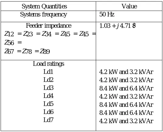
TABLE-I: GRID SYSTEM PARAMETERS
System Quantities Value
Systems frequency 50 Hz
Feeder impedance
Z12 = Z23 = Z34 = Z45 = Z45 =
Z56 =
Z67 = Z78 = Z89
1.03 + j 4.71 Ω
Load ratings Ld1 Ld2 Ld3 Ld4 Ld5 Ld6 Ld7
[image:3.612.172.440.464.681.2]Technology (IJRASET)
DG ratings (nominal) DG-1 DG-2 DG-3 5.2 kW 7.5 kW 3.0 kW Output inductances LG1 = LG2 = LG3 =
LG4
75 mH
DGs and VSCs DC voltages (Vdc1 to
Vdc4) Transformer rating
VSC losses (Rf) Filter capacitance (Cf) Hysteresis constant (h)
0.5kV
0.350kV/0.350 kV, 0.25 MVA,
2.5% Lf
1.5 Ω
50 μF
10-5
III.C O N V E R T E R STRUCTURE AND CONTROL
The converter structure that is connected to the single-phase DGs is shown in Fig. 2. Here the DG is assumed to be an
ideal dc voltage source supplying a voltage of Vdc to the VSC. The converter contains one H-bridges. The output of the
H-bridge is connected to a single- phase transformer. The resistance Rf represents the switching and transformer losses, while
the inductance Lf represents the leakage reactance of the transformers. The filter capacitor Cf is connected to the output of
the transformers to bypass switching harmonics. The inductance is physically connected to represent the output
inductance of the converter-DG source combination. The same converter structure is used for all the single
phase DG sources. The three phase compensator contains three such H- bridges. However, its connected to the PCC without any output inductance. The schematic diagram is shown in Fig. 3. It is to be noted that fore DSTACOM, the dc bus contains a dc capacitor, while for a DG-compensator; the dc bus is supplied by an ideal voltage source.
Fig. 2. Single-Phase converter structure
Technology (IJRASET)
A. Control of Single-Phase VSCs
Fig. 4. Equivalent circuit of the converter.
The single-phase VSCs are controlled under closed-loop feedback. Consider the equivalent circuit of one phase of the
converter as shown in Fig. 4. In this, u.Vdc represents the converter output voltage, where u is the switching function that
can take on values ± 1. The main aim of the converter control is to generate u. From the circuit of Fig. 4, the state space
description of the system can be given as
(1)
Where uc is the continuous time control input, based on which the switching function u is determined. The discrete-time
equivalent of (1) is
(2)
Neglecting the PCC voltage vPCC assuming it to be a disturbance input, the input-output relationship of the system in (2)
can be written in the following two forms
(3)
(4)
The feedback control laws of the converters are generated as discussed below. The single phase DGs are controlled in a sinusoidal current limiting mode. In this mode, the output current is required to produce the maximum available power. Let the current reference for the maximum available power be denoted as . This is then tracked using a pole placement method to compute
(k) from (4)
B. Feedback Control of the Compensator
In the three phase compensator structure shown in Fig. 5.6, each of the H-bridges are controlled in state feedback. For this, a
state vector can be defined as . The state feedback control is
(5)
Where K is the feedback gain matrix and is the reference state vector. In this paper, this gain matrix is obtained using
LQR method. How the references are set for either of the controller will be discussed in the next section.
C. Switching Control
Once uc(k) is computed from either state feedback or output feedback, the switching function u is generated from
(6)
Technology (IJRASET)
IV. REFERENCE GENERATIONAs mentioned in the previous section, the VSCs connoted to the single phase DGs are controlled in the current feedback mode while in the three-phase compensator is controlled in the state feedback mode. The reference generation for these two different control modes is discussed in this section.
A. Current Feedback
As discussed in the previous section when the power output of the DG suddenly reduces or the load demands more than the rated output power from the DG, it is switched to a sinusoidal current limiting mode. Let the maximum available power rating of the
DG be denoted by Prated and Qrated. The magnitude and angle of the reference current is calculated from the voltage
magnitude (VZ see fig.2) of the adjacent bus voltages as
(7)
B. Three Phase DG-Compensator Reference Generation
The main aim of the compensator is to cancel the effects of unbalanced and harmonic components of the load. If proper
compensation is achieved, the currents ig and i2 will be balanced and so will be the voltage vp provided that vs is balanced. In
addition, the DG-compensator can also supply apart of the real and reactive power required, while the DSTATCOM only supplies reactive power. In this subsection, we shall first present the generalized reference generation scheme for the DG-compensator. This will then be modified for the DSTATCOM scheme in the next sub-section. Let us denoted the three phases by the subscripts
a, b and c. Consider the circuit of Fig. 1 in which the current entering the distribution system from PCC is denoted by ig and the
current supplied to the distribution system is denoted by il. The compensator current is denoted by ic such that the Kirchhoff’s
current law (KCL) at the compensator coupling point is given by
= k=a, b, c (8)
= (9)
Therefore combining (8) and (9) by adding the currents of the all the three phases together, we get
(10)
Since ig is balanced due to the action of the compensator, the voltage vp will also become balanced provided that the supply
voltage is balanced. Hence the instantaneous real powers PG will be equal to its average components. Therefore we can write
From the KCL of (8), (11) can be written as
Similarly the reactive powers QG and QC will be equal to their instantaneous components. Therefore we can write
Using the KCL of (8), (13) can be rewritten as
Technology (IJRASET)
Substituting (17) in (16), the determinant of A is given
Computing the inverse of the matrix A, the solution of (15) is given as
Now let us stipulate that the utility supplies PG that is λp times the average power PLav supplied to the distribution
system and which is λq times the average reactive power QLav supplied to the distribution system. This is given by the
following two relations
Substituting (20), in (19), the reference currents are given by
For the state feedback control of (5), we not only need the reference currents of (21), but also the reference for the voltages
vpk, k = a,b,c and the currents through the filter capacitors (see Fig. 5.6). The reference for the voltage vp is set by
extracting the fundamental positive sequence of the voltage measurements at this point, while the capacitor current is the
derivative of this voltage multiplied by the capacitance value Cf.
C. THREE PHASE DSTATCOMREFERENCE GENERATION
Since a DSTATCOM is supplied by a dc capacitor, it can only supply a part of the reactive power and no real power.
Therefore the entire real power must come from the utility and hence in (20), the coefficient λp should be equal to 1. The
coefficient λq should be chosen based on the ratio of what portion of the reactive power should be supplied by the
DSTATCOM. Therefore the reference currents for this case are given by modifying (21) as
Note that this is a modification of the method presented in. Once the reference currents are obtained, the references of the voltage
Technology (IJRASET)
V. SIMULATION STUDIESSimulation studies are carried out in MATLABR2008a (version 7.6). The DGs are considered as inertia-less dc sources supplied through the VSCs
Case-1: DSTATCOM Connected at PCC
(a) Three-phase currents from utility
(b) Three phase compensator Current
( c) Reactive power sharing with DSTATCOM
Technology (IJRASET)
To compensate the imbalance among the phases, at first a DSTATCOM is connected as a three phase
compensator. As discussed previously, DSTATCOM can share the reactive power requirement with utility in a pre-
specified ratio. The DSTATCOM is connected to the system at 0.2 s and it is desired that DSTATCOM supply the 70% of the reactive power while balancing the utility currents. The system responses are shown from fig. (a),(b),(c). Fig. (a) shows the utility and DSTATCOM current. It can be seen that the utility currents gets balanced after the DSTATCOM connection. However, the DSTATCOM supplies unbalanced currents to compensate for the downstream unbalance. It can be seen that DSTATCOM and the utility share the reactive power 7:3 ratio as desired. Also the DSTATCOM reactive power oscillates with sympathy with load reactive power, while QG becomes flat. The PCC voltage becomes balanced within 3-4 cycles after the DSTATCOM is connected to the system and motor torque pulsation disappears and it becomes constant.
Case-2: DG-Compensator Connected at PCC
While the DSTATCOM can only provide the required reactive power, a compensator connected with DG can also share the real power burden of the utility. Let us assume that the DG-compensator supplies 30% of the real and reactive power demand
(PL, QL), when it gets connected to the system at 0.45 s.
(a)Three phase current from utility
(b)Three phase current from DG-compensator
c) Real Power from Sharing
Technology (IJRASET)
(e) Induction motor Electrical Torque
From the fig. the utility currents get balanced as soon as the DG- compensator is connected. The induction motor pulsation also ceases. The total harmonic distortion (THD) of the grid voltage is about 10% and the negative and zero sequence components are around 5% of the positive sequence component before DG-compensation connection. These are then reduced such that the THD becomes less than 0.5%,whereas, negative and zero sequence components of the voltages remain below 0.02% once the DG- compensator is connected.
VI.CONCLUSION
In this Paper, the operation and control of single phase DGsources are considered in a three-phase utility connected grid. The single phase sources are operated to deliver available maximum power generated while the rest of the power demands in each of the phases are supplied by utility (and if available, three phase DG sources). The imbalance in three phase power is compensated two ways –either through a DSTATCOM or through a DG-compensator. A DSTATCOM can compensate for unbalances and nonlinearities, while providing reactive power support. The size of the dc capacitor determines how much reactive power support the DSTATCOM can provide without any drop in voltage. The choice of this capacitor is thus a trade-off between the reactive support and system response. Alternatively a three phase DG-compensator can be connected at the PCC to share the real and reactive power with utility and to compensate for the unbalance and nonlinearities in the system.
The efficacy of the compensation is validated through extensive simulations and calculation of THD With the
proposed structure of distribution system, it is possible to operate single phase DG sources in a utility connected grid and this might become a useful tool as their penetration in distribution systems increases.
REFERENCES
[1]B. K. Bose, “Energy, environment, and advances in power electronics,” IEEE Trans. on Power Electronics, vol. 15, pp. 688–701, July 2000.
[2] X. Yoasuo, C. Liuchen, B. K. Soren, B. Josep and S. Toshihisa, “Topologies of single-phase inverters for small distributed power generators: an overview”, IEEE Trans. on Power Electronics, vol. 19, pp. 1305-1314, Sep 2004
[3] T. E. McDermott, R. C. Dugan, “Distributed generation impact on reliability and power quality indices” Rural Electric Power Conference, 2002, pp D3-D3_7.
[4] Y. W. Li, D. M. Vilathgamuwa and P. C. Loh, “A grid- interfacing power quality compensator for three-phase three- wire microgrid applications,” IEEE Trans on Power Electronics, Vol. 21, Issue 4, pp.1021-1031, July 2006
[5] A. Ghosh, A. K. Jindal and A. Joshi, “Inverter control using output feedback for power compensating devices,” Proc. IEEE Asia-PacificRegion-10 Conference TENCON, Bangalore, pp. 49-52, October 2003.
[6] A. Ghosh and G. Ledwich, "Load compensating DSTATCOM is weak ac systems," IEEE Trans. Power Delivery, Vol. 18, No. 4, pp. 1302-1309, 2003.
[7] W. Freitas, A. Morelato, X. Wilsun and F. Sato, “Impacts of ac generators and DSTATCOM devices on the dynamic performance of distribution systems,” IEEE Trans. On Power Delivery, Vol. 20, No. 2, pp. 1493-1501, 2005.
[8] J. M. Guerrero, L. Garcia de Vicuna, and J. Uceda, “Uninterruptible power supply systems provide protection,” IEEE Ind. Electron. Mag., vol. 1, no. 1, pp. 28–38, Spring, 2007.
[9] B.Wang, G. Venkataramanan, and M. Illindala, “Operation and control of a dynamic voltage restorer using transformer coupled H-bridge converters,” IEEE Trans. Power. Electron., vol. 21, no. 4, pp. 1053–1061, Jul. 2006.
[10] D. M. Vilathgamuwa, H. M. Wijekoon, and S. S. Choi, “A novel technique to compensate voltage sags in multiline distribution system—The interline dynamic voltage restorer,”IEEE Trans. Ind. Electron., vol. 53, no. 5, pp. 1603–1611, Oct.2006.]
[11] C. N. M. Ho and H. S. H. Chung, “Fast transient control of singlephase Dynamic Voltage Restorer (DVR) without external DC source,” in Proc. 37th IEEE Power Electronics Specialists Conf., Jeju, Korea, Jun. 18–22, 2006, pp. 2105–2111.
[12] M. R. Banaei, S. H. Hosseini, and M. D. Khajee, “Mitigation of voltage sag using adaptive neural network with dynamic voltage restorer,” in Proc. 5th Int. CES/IEEE Power Electronics and Motion Control Conf., Shanghai, China, Aug.14–16, 2006, vol. 2, pp. 1–5.