Technology (IJRASET)
Implementation of a Fast Binary Floating Point
Dadda Multiplier
Thalari Mohan1, G.Mukesh2, M.Tech
Department of Electronics and Communication Engineering, Audisankara College of Engineering & Technology, Gudur. (Autonomous)
Abstract: This project presents a high speed binary floating point multiplier based on Dadda Algorithm. To improve speed multiplication of mantissa is done using Dadda multiplier replacing Carry Save Multiplier. The design achieves high speed with maximum frequency of 526 MHz compared to existing floating point multipliers. The floating point multiplier is developed to handle the underflow and overflow cases. To give more precision, rounding is not implemented for mantissa multiplication. The multiplier is implemented using Verilog HDL and it is targeted for Xilinx Virtex-5 FPGA. The multiplier is compared with Xilinx floating point multiplier core.
Index Terms— Dadda Algorithm; Floating point; multiplication; FPGA, Verilog HDL;
I. INTRODUCTION
Most of the DSP applications need floating point numbers multiplication. The possible ways to represent real numbers in binary format floating point numbers are; the IEEE 754 standard [1] represents two floating point formats, Binary interchange format and Decimal interchange format. Double precision normalized binary interchange format is implemented in this design. Representation of double precision binary format is shown in Figure 1; starting from MSB it has a one bit sign (S), an eight bit exponent (E), and a twenty three bit fraction (M or Mantissa). Adding an extra bit to the fraction to form and is defined as significand1. If the exponent is greater than 0 and smaller than 255, and there is 1 in the MSB of the significand then the number is said to be a normalized number; in this case the real number is represented by (1).
64 63 52 51 1 0
Sign Exp Mantissa
Fig.1: IEEE Double precision floating point format Z = (-1S) * 2 (E - Bias) * (1.M) (1)
Where,
M = n22 2-1 + n21 2-2 + n20 2-3+…+ n1 2-22+ n0 2-23; Bias = 1023.
1
Significand is the extra MSB bit appended to mantissa. Floating point multiplication of two numbers is made in four steps: Step 1: Exponents of the two numbers are added directly, extra bias is subtracted from the exponent result.
Step 2: Significands multiplication of the two numbers using Dadda algorithm.
Step 3: To find the sign of result, XOR operation is done among sign bit of two numbers.
Step 4: Finally the result is normalized such that there should be 1 in the MSB of the result (leading one).
Technology (IJRASET)
point unit using the primitives of Xilinx Virtex II FPGA was implemented with a latency of 4 clock cycles. The multiplier reached a maximum clock frequency of 100MHz.
II. FLOATING POINT MULTIPLIER ALGORITHM
The normalized floating point numbers have the form of
Z= (-1S) * 2 (E - Bias) * (1.M). The following algorithm is used to multiply two floating point numbers.
Significand multiplication; i.e. (1.M1*1.M2). Placing the decimal point in the result. Exponent’s addition; i.e. (E1 + E2 - Bias). Getting the sign; i.e. s1 xor s2.
Normalizing the result; i.e. obtaining 1 at the MSB of the results’ significand. Rounding implementation.
Verifying for underflow/overflow occurrence.
Consider the following IEEE 754 double precision floating point numbers to perform the multiplication, but the number of mantissa bits is reduced for simplification. Here only 5 bits are considered while still considering one bit for normalized numbers:
A = 0 10000001 01100 = 5.5, B = 1 10000100 00011 = -35 By following the algorithm the multiplication of A and B is
A. Significand Multiplication:
B. Normalizing the result: 1.1000000100
C. Adding two exponents: 10000001 +10000100 100000101
The result after adding two exponents is not true exponent and is obtained by subtracting bias value i.e. 1023. The same is shown in following equations.
EA = EA-true + bias EB = EB-true + bias
EA + EB = EA-true + EB-true + 2 x bias Therefore
Etrue= EA + EB – bias.
From the above analysis bias is added twice so bias has to be subtracted once from the result. 100000101
-001111111 10000110
D. Sign bit of result is extracted by doing XOR operation of sign bit of two numbers: 1 10000110 01.1000000100
E. Then normalize the result so that there is a 1 just before the radix point (decimal point). Moving the radix point one place to the left increments the exponent by 1; moving one place to the right decrement the exponent by 1.
Technology (IJRASET)
then the stored value is:
1 10000110 10000.
In this we are presenting a floating point multiplier in which rounding support is not implemented. By this we get more precision in MAC unit and this will be accessed by the multiplier or by a floating point adder unit.
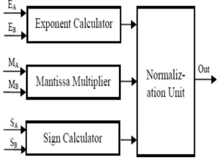
Figure 2 shows the block diagram of the multiplier structure; Exponents calculator, Mantissa multiplier and sign bit calculator, using the pipelining concept here all processes are carried out in parallel.
[image:4.612.196.413.202.362.2]Two 24 bit significands are multiplied and the result is a 48 bit product, denoting this as Intermediate Result (IR). The IR width is 48-bit i.e. 47 down to 0 and the decimal point is located between bits 46 and 45 in the IR. Each block is elaborated in the following sections.
Fig.2: Floating point multiplier block diagram
III. MAIN BLOCKS OF FLOATING POINT MULIPLIER
A. Sign calculator
The main component of Sign calculator is XOR gate. If any one of the numbers is negative then result will be negative. The result will be positive if two numbers are having same sign.
B. Exponent Adder
This sub-block adds the exponents of the two floating point numbers and the Bias (1023) is subtracted from the result to get true result i.e. EA + EB – bias. In this design the addition is done on two 8 bit exponents. In previous designs the most of the computational time is spending in the significand multiplication process (multiplying 24 bits by 24 bits); so quick result of the addition is not necessary. Thus we need a fast significand multiplier and a moderate exponent adder.
To perform addition of two 8-bit exponents an 8-bit ripple carry adder (RCA) is used. As shown in Figure 3 the ripple carry adder consists an array of one Half Adder (HA) (i.e. to which two LSB bits are fed) and Full Adders (FA) (i.e. to which two input bits and previous carry are given).
[image:4.612.202.422.596.698.2]The HA has two inputs and two outputs and FA has three inputs (Ao, Bo, Ci) and two outputs (So, Co). The carry out (Co) of each adder is fed to the next full adder (i.e. each full adder has to wait for carry out of preceding).
Fig.3: Ripple Carry Adder
Technology (IJRASET)
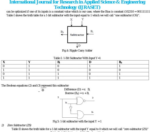
can be optimized if one of its inputs is a constant value which is our case, where the Bias is constant (102310 = 0011111112). Table I shows the truth table for a 1-bit subtractor with the input equal to 1 which we will call “one subtractor (OS)”.
Fig.4: Ripple Carry Adder
Table I: 1-Bit Subtractor With Input Y=1
X Y Bi D B0
0 1 0 1 1
1 1 0 0 0
0 1 1 0 1
1 1 1 1 1
The Boolean equations (2) and (3) represent this subtractor
Difference (D) = x Bi Borrow (B0) = x + Bi
Fig.5: 1-bit subtractor with the input Y = 1
[image:5.612.36.562.42.502.2]2) Zero Subtractor (ZS)
Table II shows the truth table for a 1-bit subtractor with the input Y equal to 0 which we will call “zero subtractor (ZS)” Table II: 1-Bit Subtractor With The Input Y=0
X Y Bi D B0
0 0 0 0 0
1 0 0 1 0
0 0 1 1 1
1 0 1 0 0
[image:5.612.43.560.509.710.2]Difference (D) = s Bi Borrow (B0) = s. Bi
Technology (IJRASET)
Fig. 7 shows the Bias subtractor which is a chain of 7 one subtractors (OS) followed by 2 zero subtractors (ZS); the borrow output of each subtractor is fed to the next subtractor. If an underflow occurs then Eresult < 0 and the number is out of the IEEE 754 double precision normalized numbers range; in this case the output is signaled to 0 and an underflow flag is asserted.
Fig.7: Ripple Borrow Subtractor
C. Significand multiplication using Unsigned Multiplier 1) Existing Multiplier:
Carry Save Multiplier:
This unit is used to multiply the two unsigned significand numbers and it places the decimal point in the multiplied product. The unsigned significand multiplication is done on 24 bit. The result of this significand multiplication will be called the IR. Multiplication is to be carried out so as not to affect the whole multiplier’s performance. In this carry save multiplier architecture is used for 24X24 bit as it has a moderate speed with a simple architecture. In the carry save multiplier, the carry bits are passed diagonally downwards (i.e. the carry bit is propagated to the next stage). Partial products are generated by ANDing the inputs of two numbers and passing them to the appropriate adder. Carry save multiplier has three main stages:
The first stage is an array of half adders.
The middle stages are arrays of full adders. The number of middle stages is equal to the significand size minus two. The last stage is an array of ripple carry adders. This stage is called the vector merging stage.
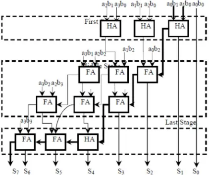
The count of adders (Half adders and Full adders) in each stage is equal to the significand size minus one. For example, a 4x4 carry save multiplier is shown in Figure 8 and it has the following stages:
The first stage consists of three half adders.
Two middle stages; each consists of three full adders.
The vector merging stage consists of one half adder and two full adders.
[image:6.612.206.417.525.702.2]The decimal point is placed between bits 45 and 46 in the significand multiplier result. The multiplication time taken by the carry save multiplier is determined by its critical path. The critical path starts at the AND gate of the first partial products (i.e. a1b0 and a0b1), passes through the carry logic of the first half adder and the carry logic of the first full adder of the middle stages, then passes through all the vector merging adders. The critical path is marked in bold in Figure 8.
Technology (IJRASET)
In Figure 8
1. Partial product: aibj ai and bj 2. HA: half adder.
3. FA: full adder.
2) Proposed multiplier Dadda Multiplier:
Dadda proposed a sequence of matrix heights that are predetermined to give the minimum number of reduction stages. To reduce the N by N partial product matrix, dada multiplier develops a sequence of matrix heights that are found by working back from the final two-row matrix. In order to realize the minimum number of reduction stages, the height of each intermediate matrix is limited to the least integer that is no more than 1.5 times the height of its successor.
The process of reduction for a dadda multiplier [7] is developed using the following recursive algorithm
Let d1=2 and dj+1 = [1.5*dj], where dj is the matrix height for the jth stage from the end. Find the smallest j such that at least one column of the original partial product matrix has more than dj bits.
In the jth stage from the end, employ (3, 2) and (2, 2) counter to obtain a reduced matrix with no more than dj bits in any column. Let j = j-1 and repeat step 2 until a matrix with only two rows is generated.
This method of reduction, because it attempts to compress each column, is called a column compression technique.
Another advantage of utilizing Dadda multipliers is that it utilizes the minimum number of (3, 2) counters. {Therefore, the number of intermediate stages is set in terms of lower bounds: 2, 3, 4, 6, 9 . . .
For Dadda multipliers there are N2 bits in the original partial product matrix and 4.N-3 bits in the final two row matrix. Since each (3, 2) counter takes three inputs and produces two outputs, the number of bits in the matrix is reduced by one with each applied (3, 2) counter therefore}, the total number of (3,2) counters is #(3, 2) = N2 – 4.N+3 the length of the carry propagation adder is CPA length = 2.N–2.
Fig.9: Dot diagram for 8 by 8 Dadda Multiplier
The number of (2, 2) counters used in Dadda’s reduction method equals N-1.The calculation diagram for an 8X8 Dadda multiplier is shown in figure 9.
Dot diagrams are useful tool for predicting the placement of (3, 2) and (2, 2) counter in parallel multipliers. Each IR bit is represented by a dot.
Technology (IJRASET)
delay, one (3, 2) counter delay for each of the four reduction stages, and the delay through the final 14-bit carry propagate adder arrive later, which effectively reduces the worst case delay of carry propagate adder.
The decimal point is between bits 45 and 46 in the significand IR. Critical path is used to determine the time taken by the Dadda multiplier. The critical path starts at the AND gate of the first partial products passes through the full adder of the each stage, then passes through all the vector merging adders. The stages are less in this multiplier compared to the carry save multiplier and therefore it has high speed than that.
D. Normalizing Unit
The result of the significand multiplication (intermediate product) must be normalizing. Having a leading ‘1’ just immediate to the left of the decimal point (i.e. in the bit 46 in the intermediate product) is known as a normalized number. Since the inputs are normalized numbers then the intermediate product has the leading one at bit 46 or 47.
1) No shift is needed the intermediate product is known to be a normalized number when the one is at bit 46 (i.e. to the left of the decimal point) .
2) The exponent is incremented by 1 if the leading one is at bit 47 then the intermediate product is shifted to the right. Multiplexers are used to perform combinational shift logic for the shift operation.
IV. UNDERFLOW/OVERFLOW PREDICTION
Underflow/Overflow means that the result’s exponent is too small/large to be represented in the exponent field. The result of exponent must be 8 bits in size, and must be between 1 and 254 otherwise the value is not a normalized one. While adding the two exponents adding or during normalization the overflow may occur. Overflow due to exponent addition may be compensated during subtraction of the bias; resulting underflow that can never be compensated; if the intermediate exponent = 0 then during normalization it’s an underflow that may be compensated by adding 1 to it.
If an overflow occurs an overflow signal is made high and the result turns to ±Infinity (sign determined according to the sign of the floating point multiplier inputs). If an underflow occurs an underflow signal goes high and the result turns to ±Zero (sign determined according to the sign of the floating point multiplier inputs). An underflow flag is raised after denormalized numbers are made to Zero with the appropriate sign calculated from the inputs. Assume that E1 and E2 are the exponents of the two numbers A and B respectively; the result’s exponent is calculated by (6)
Eresult = E1 + E2 - 1023 (6)
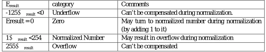
[image:8.612.93.518.508.592.2]E1 and E2 can have the values from 1 to 254; resulting in Eresult having values from -125 (2-1023) to 381 (508-1023); but for normalized numbers, Eresult can only have the values from 1 to 254. Table III summarizes the Eresult different values and the effect of normalization on it.
Table III: Normalization Effect On Result’s Exponent And Overflow/Underflow Detection
Eresult category Comments
-125≤ Eresult <0 Underflow Can’t be compensated during normalization.
Eresult = 0 Zero May turn to normalized number during normalization (by adding 1 to it)
1≤ Eresult <254 Normalized Number May result in overflow during normalization 255≤ Eresult Overflow Can’t be compensated
V. MULTIPLIER PIPELINING
In order to enhance the performance of the multiplier, three pipelining stages are used to divide the critical path thus increasing the maximum operating frequency of the multiplier. The pipelining stages are imbedded at the following locations:
A. Before the bias subtraction; in the middle of the significand multiplier and in the middle of the exponent adder.
B. After the significand multiplier and the exponent adder.
Technology (IJRASET)
Fig.10: Figure shows the pipelining stages as dotted lines.
The synthesis tool “retiming” option was used so that the synthesizer uses its optimization logic to better place the pipelining registers across the critical path.
VI. SIMULATION RESULTS
The simulation of the proposed design is carried out by using Verilog HDL language in Xilinx ISE simulator tool. The simulated results of the proposed design is as shown in below figure:
Fig.11 RTL schematic of proposed design
Technology (IJRASET)
Fig.13 simulation results of proposed design
VII. CONCLUSION
This paper describes an implementation of a floating point multiplier using Dadda Multiplier that supports the IEEE 754- 2008 binary interchange format; the multiplier is more precise because it doesn’t implement rounding and just presents the significand multiplication result as is (48 bits). The significand multiplication time is reduced by using Dadda Algorithm.
REFERENCES
[1] IEEE 754-2008, IEEE Standard for Floating-Point Arithmetic, 2008.
[2] Mohamed Al-Ashrfy, Ashraf Salem and Wagdy Anis “An Efficient implementation of Floating Point Multiplier” IEEE Transaction on VLSI 978-1-4577-0069-9/11@2011 IEEE, Mentor Graphics.
[3] B. Fagin and C. Renard, “Field Programmable Gate Arrays and Floating Point Arithmetic,” IEEE Transactions on VLSI, vol. 2, no. 3, pp. 365- 367, 1994. [4] N. Shirazi, A. Walters, and P. Athanas, “Quantitative Analysis of Floating Point Arithmetic on FPGA Based Custom Computing Machines,” Proceedings of the IEEE Symposium on FPGAs for Custom Computing Machines (FCCM’95), pp.155-162, 1995.
[5] L. Louca, T. A. Cook, and W. H. Johnson, “Implementation of IEEE Double precision Floating Point Addition and Multiplication on FPGAs,” Proceedings of 83 the IEEE Symposium on FPGAs for Custom Computing Machines (FCCM’96), pp. 107-116, 1996.
[6] Jaenicke and W. Luk, "Parameterized Floating-Point Arithmetic on FPGAs", Proc. of IEEE ICASSP, 2001, vol. 2, pp.897-900.
[7] Whytney J. Townsend, Earl E. Swartz, “A Comparison of Dadda and Wallace multiplier delays”. Computer Engineering Research Center, The University of Texas.
[8] B. Lee and N. Burgess, “Parameterisable Floating-point Operations on FPGA,” Conference Record of the Thirty-Sixth Asilomar Conference on Signals, Systems, and Computers, 2002.
[9] Xilinx13.4, Synthesis and Simulation Design Guide”, UG626 (v13.4) January 19, 2012.
T.MOHAN received his B.Tech degree in Electronics and Communication Engineering from N.B.K.R.I.S.T COLLEGE, Vidhyanagar, Nellore District, affiliated to SVU Tirupati.He is currently pursuing M.Tech VLSI in Audisankara college of Engineering and Technology,gudur(autonomous),SPSR Nellore(Dist),affiliated to JNTU Anantapur.