~
---MP/M
JITM
OPERATING SYSTEM
SYSTEM
GUIDE
MP/M Ir
MOperating System
SYSTEM IMPLEMENTOR'S GUIDE
Copyright ~ 1981
Digital Research P.O. Box 579 801 Lighthouse Avenue
Pacific Grove, C~ 93950
(408) 649-3896
TWX 910 360 5001
COPYRIGHT
Copyright 1981 by Digital Research. All rights
reserved. No part of this publication may be
reproduced, transmitted, transcribed, stored in a retrieval system, or translated into any language or computer language, in any form or by any means, electronic, mechanical, magnetic, optical, chemical, manual or otherwise, without the prior written permission of Digi tal Research, Post Office Box 579, Pacific Grove, California, 93950.
DISCLAIMER
Digital Research makes no representations or warranties with respect to the contents hereof and spec ifically disclaims any implied warranties of merchantability or fitness for any particular
purpose. Further, Digi tal Research reserves the
right to revise this publication and to make changes from time to time in the content hereof without obligation of Digital Research to notify any person of such revision or changes.
TRADEMARKS
CP/M is a registered trademark of Digital Research.
CP INET, MP 1M II, LINK-80, RMAC and PL/I-80 are
trademarks of Digital Research. Z80 is a registered trademark of Zilog, Inc.
The "MP/M II SYSTEM GUIDE" was prepared using the Digital Research TEX-80 Text Formatter and printed in the United States of America by Commercial Press
I
Monterey.************************************
*
First Edition: September 1981*
*
Second Edition: August 1982*
Foreword
MP/M IIT
.M. is a multi-user operating system for any
microcomputer based on an 8-bit Zilog Z80® or Intel 8080 or 8085 microprocessor. Typically, an lViP/M II system resides in approximately 27k. 16k of the operating system must reside in common memory.
The version of MP/M II that Digital Research ships cannot be directly booted on any specific hardware configuration. However, all the hardware-dependent code is isolated in specific subroutines that can be modified by the u~er.
This document describes the procedures required to implement MP/M II for a custom hardware environment. At minimum, the custom hardware environment must include an 8080, 8085, or Z-80 processor, 32K bytes of random access memory (RAM), a system console, and a
real~time clock. This manual assumes the reader is familiar with
the following Digital Research publications:
• MP/M II User's Guide
• MP/M II Programmer's Guide
Table of Contents
1 MP/M II Alteration Procedure
1.1 preparation for MP/M II Alteration 1
1.2 Customizing the MPMLDR
· · ·
21.3 Customizing the XIOS
· ·
·
·
·
· ·
·
31.4 Debugging an XIOS
.
.
41.5 . Directly Booting MP/M II
·
· ·
·
6'1.5.1 Preparing an MP/M II Boot Using SYSGEN
·
·
· ·
71.5.2 Custom Generation of an MP/M II Boot
·
81.6 Loading MPM.SYS Wi thout the MPMLDR
· · · ·
111.7 Digital Research Copyright and Trudemark 11
1.8 Disk Organization
. . · · · .
. ·
·
·
·
·
·
122 The MP/M II BIOS
2.1 MP/M II BIOS Overview
·
·
·
· · ·
·
152.2 BIOS De,vice Characteristics and Entry Points 16
2.3 BIOS Disk Definition Tables
· · ·
· ·
·
242.3.1 Disk Parameter Table Format 24
2.3.2 The DISKDEF Macro Library 29
2.4 Externa,l Procedu,re Access
· · ·
. .
·
· ·
·
332.5 Blocking and Deblocking Algorighms
·
·
· ·
362.6 Common Memory Portion of the BNKXIOS
· ·
·
373 The MP/M II XIOS
3.1 MP/M II XIOS Overview
.
.
· ·
·
·
·
·
393.2 MP/M XIOS Entry Points
. ·
·
·
39Table of Contents
(continued)
4 MP/M II System File Components
4.1 System Data • •
4.2 Customized XIOS • 4.3 BDOS
4 .. 3.1 RESBDOS
4.3.2 BNKBDOS
4.4 XDOS
4.5 Resident System Processes.
4.6 Banked Resident System Processes
5 System Generation
5.1 GENSYS Operation
5.2 System Gener2tion Parameters
r: ?
::>.J
5.2.1 5.2.2 5.2.3 5.2.4 5.2.5 5.2.6 5.2.7 5.2.8 5.2.9 5.2.10 5.2.11 5.2.12 5.2.13 5.2.14 5.2.15 5.2.16 5.2.17 5.2.18 5.2.19 5.2.20 5.2.21 5.2.22
Defaults • . • • . • • •
Top Page of Opersting System . Number of System Consoles Number of Printers • • • • Breakpoint RST • • • • • • System Call User Stacks Z80 CPU • • • • • • . • •
Number of Ticks / Second • • • • • • System Disk • • . • . •
Temporary File Drive . . ~ . • Maximum Locked Records / Process Total Locked Records / System Maximum Open Files / Process . Total Open Files / System
Bank Switched Memory • • • • • Number of User Memory Segments • Common Memory Base Page
Dayfile Logging at Console • • • • • . Accept System Data Page Entries
Select Resident System Processes • Memory Segment Table • . . . • Accept MemolY Segment Table
GENSYS Execution
vi
47
48
48 48 49 49
49
49
51
52
52 53 53 53 53 53 54 54 54 54 54 54 55 55 55 55 55 55 56 56 56 57
Table of Contents
( continued)
6 MP/M Loader
6.1 MP/M Loader Operation and Display • •
6.2 MPMLDR Execution
Appendixes
A Disk Definition lVlacro
. . . .
· · ·
B Sector Deblocking Algorithms
.
· ·
·
C Sample MP/M II Loader BIOS
· ·
·
D Simple XIOS Source Listing
E Sample MP/M II Banked XIOS
.
.
..59 60
·
61·
.
. .
.
67·
7577
Section
1
MP 1M II Alteration Procedure
The MP/M II operating system is designed so that the user can alter a specific set of subroutines that define the hardware operating environment. By modifying these subroutines, the user can produce Gl diskette that operates with any IBrvI-3740 format compatible
diskette subsystem and other peripheral devices.
Although the standard MP/M II is shipped on single-density floppy disks, field-alteration features c:;llow the user to adapt MP/M II to a wide variety of disk subsystems, including single drive minidisks and high-capacity "hard disk" systems.
To achieve device independence, MP/M II has isolated (']11 hardware-dependent code into an XIOS module. The user can rewrite the distributed version of the XIOS to customize the interface between the remaining MP/M II modules and the user's own hardware system. The user can also rewrite the distributed version of the LDRBIOS, which loads the MP/M II system from disk.
There are actually two versions of the XIOS: the RESXIOS for non-banked systems, and the BNKXIOS for banked memory systems. To avoid repeating both names for each reference, the term XIOS refers to both versions.
1.1 Preparation for MP/M II Alteration
To s impl i fy the al te rat ion process, th i s document assumes tha t a CP/M 2 BIOS has already been implemented on the target MP/M II mach ine. You must implement both the BIOS as well as the XIOS because the MP/M II loader uses a CP/M 2 BIOS to load the MP/M II system. Once loaded, MP/M II uses the XIOS and not the BIOS. The CP/M 2 BIOS used by the MP/M II loader is called the LDRBIOS.
MP/M II System Guide 1.2 Customizing the MPMLDR
1.2 Customizing the MPMLDR
To customize the MPMLDR, you must integrate a LDRBIOS for your hardware configuration into the MPMLDR.COM file supplied on the
distribution disk. The required LDRBIOS can be simply a version of
your CP/M 2 BIOS, altered as described below and renamed to LDRBIOS.
The customized LDRBIOS must have an ORG of 1700H, perform console output functions, and be able to read data from a single
disk drive. 'rhe first call MPMLDR makes to LDRBIOS is SELDSK:
select disk. If your system has devices that require
initialization, place initialization code or perhaps a call to the LDRBIOS cold start at the beginning of the SELDSK handler.
The LDRBIOS need only perform the opErations described above. Other functions can be deleted to conserve space. There is only one
restriction on memory space for LDRBIOS: it cannot extend above the
base of the MPM.SYS which it is loading. (GENSYS Lists MP/M II's
base address in its load map.) However, if you plan to boot MP/M II
from floppy disks, you will encounter a LDRBIOS upper address limit of lAOOH in order to place the MPMLDR.COM file on two system tracks.
Test LbRBIOS completely to ensure that i t properly performs console character output and disk reads. Be especially careful that no disk write operations occur accidently during read operations, and check that the proper track and sectors are addressed on all reads.
Use the following steps to integrate a custom LDRBIOS into the MPMLDR.COM:
1. Obtain access to a CP/M system and prepare a LDRBIOS.HEX file.
2. Read the MPMLDR.COM file into memory using either DDT or SID.
A)DDT MPMLDR.COM
DDT VERS 2.0 NEXr!, PC 1780 0100
3. Using the input command (I), specify that the LDRBIOS.HEX file
is to be read in and then read (R) in the file. This operation overlays the LDRBIOS portion of the MP/M loader.
--ILDRBIOS .HEX
-R
NEXT PC
lAOO 0000
All Information Presented Here is Proprietary to Digital Research
MP/M II System Guide 1.2 Customizing the MPMLDR
4. Exit the debugger, returning to the CCP by executing a jump to location zero.
-GO
5. Write the updated memory image onto a disk file. Use the CP/M SAVE command to write the updated memory image onto a disk file. In the example below, the X in front of the filename simply designates an experimental version, and preserves the original.
A>SAVE 26 XMPMLDR.COM
6. Test XMPMLDR.COM and then rename i t to MPMLDR.COM.
1.3 Customizing the XIOS
As you are tailoring MP/M II for your computer system, your new XIOS will require software development and tEsting. 'rwo sample XIOS's are listed in the Appendixes, and can be used as models for the customized package.
The XIOS entry points, including both basic and extended, are described in Sections 2 and 3. These sections, along with the appendixes, give you the information you need to write your XIOS. Your initial implementation of an XIOS should use polled I/O without any interrupts. This initial system can run without a clock interrupt. Implement interrupts only after your XIOS is fully developed and tested.
Follow the procedure below to pr-epare a BNKXIOS.SPR or RESXIOS.SPR file from your customized XIOS:
1. Assemble your BNKXIOS .ASM or RESXIOS .ASIVl wi th RMAC or- any other' assembler that can generate a file of type REL in Microsoft's relocatable object file format.
A>RMAC BNKXIOS
2. Link the BNKXIOS.REL or RESXIOS.REL file using the Digital Research LINK-80 to produce the BNKXIOS.SPR or RESXIOS.SPR file.
MP/M II System Guide 1.4 De~ugging an XIOS
1.4 Debugging an XIOS
You can debug an XIOS or a resident system process with DDT or
SID running under CP/M. The debugging technique is outlined in the
following steps:
1. Determine the amount of memory available to MP/M II when the
debugger and CP/M are resident. Do this by' loading the
debugger and then listing the jump instruction at location
OOOSH. This jump is to the base of the debugger.
A)DDT
DDT VERS 2.0 -L5
0005 JMP'C800
2. Using GENSYS running under CP/M, generate" an MPM.SYS file that
specifies the top of memory determined by the previous step,
allowing at least 256 bytes for a patch area.
Top page of operating system (xx) ? C6
Also while executing GENSYS, specify a breakpoint restart
number different from the one used by the CP/M debugger you
plan to use. The suggested MP/M II restart is #6; however,
any restart from ~tl to :ltG, can usually be used. The CP/M
debuggers normally use restart #7.
Breakpoint RST (xx) ? 6
Note: If you are alsodeuugging a resident system .process, be
sure to select it for fnclusion in MPM.SYS during GENSYS execution.
3. Using CP/M, load the MPMLDR.COM file into memory.
A)DDT MPMLDR.COM DDT VERS 2.0
NEXT PC
IAOO 0100
All Information Presented Here is Proprietary to Digital Research
MP/M II System Guide 1.4 Debugging an XIOS
4. Place the char acters n$B n into locations OOSOH and OOSEH of the default FCB based at OOSCH. This operation can be done with the I command:
-1$8
The "$B" causes the MPMLOR to break after loading the MPM.SYS file. You can specify the breakpoint restart to be executed by the MPMLDR by adding one additional character to the string in the fourth position of the default FCB.
-1$86
In the example above, a restart #6 is to be executed by the MPMLDR when loading of the MPM.SYS file is completed. If no restart number is supplied, the default restart is #7. Remember, the restart number at the location SFH is the CP/M debugger restart number, not the MP/M debugger restart.
5. Execute the MPMLOR.COM program by entering a G command:
-G
6. Af ter the G command, the MP/M I I loader loads the MP/M I I operating system into memory and displays a memory map. You may obtain a hard copy of your load map during the GENSYS operation by entering a
Tp
before executing GEN5YS.7. If you are debugging an XIOS, note the address of the BNKXrOS.SPR or RESXIOS.SPR memory segment. You must also note the address of SYSTEM. OAT. If you are debugging a resident system process, note its address as well. The debugger lists actual addresses at the console. If your hard copy listing of the XIOS or RSP starts at zero, you must add the base address listed in the GENSYS load map to each address on the listing to make the 1 isting reflect actual addresses. Or you can assemble the code again with an additional ORG statement specifying the base listed in the load map, although the object code generated by this assembly is unusable.
8. Using the X command, determine the MP/M II beginning execution address. The address is the first location past the current program counter.
-x
.
.
.
. . .
.
. . .
.
.
. .
.
.
.
. . .
P == 09F2 •••••MP/M II System Guide 1.4 Debugging an XIOS
9. Begin execution of MP/M II using the G command, specifying the start address and any breakpoints you need in your code. The actual memory address can be determined by entering an H command to add the code segment base address given in the memory map to the relative displacement address in your XIOS or
resident system process listing.
The following example shows how to set a breakpoint in an XIOS at the l i s t subroutine entry point given in the memory map:
XIOSJMP TBL C300H OlOOH
-G9F3,C30F
09F3H is the beginning MP/M II execution address and C30FH is the XIOS jump vector address of the list subroutine.
10. At this point, you have MP/M II running with CP/M and the CP/M debugger also in memory. Because interrupts are left enabled during operation of the CP/M debugger, ensure that interrupt-driven code does not execute through a breakpoint.
Because the CP/M debugger operates with interrupts left enabled, i t is a somewhat difficult task to debug an interrupt-driven console handler. Approach this problem by leaving console #0 in a polled mode while debugging the other consoles in an interrupt-driven mode. Once this is done, very l i t t l e , if any, debugging is required to adapt the interrupt-driven code from another console to console #0. It is further recommended that you maintain a debug version of your XlOS that has polled I/O for console #0. Otherwise, i t is not possible to run the CP/M debugger underneath the MP/M II system because the CP/M debugger cannot get any console input, as all of i t is sent to the MP/M interrupt-driven console #0 handler.
1.5 Directly Booting MP/M II
In systems where MP/M II is to be booted directly at cold start rather than loaded and run as a transient program under CP/M, the customized MPMLDR.COM file and cold start loader can be placed on the first two tracks of a eight-inch floppy disk. If a CP/M SYSGEN.COM program is available, use i t to write the MPMLDR.COM file on the first two tracks. If a SYSGEN.COM program is not available, or if SYSGEN.COM does not work because a different media such as a five-inch floppy disk or hard disk is to be used, the user must write two programs: a simple memory loader, called GETSYS, which brings the MP/M loader into memory, and a program called PUTSYS, which places the MPlVILDR on the first two tracks of a disk. If you have implemented a CP/M 2 BIOS, you have probably already prepared GETSYS and PUTSYS.
All Information Presented Here is Proprietary to Digital Research
MP/M II System Guide 1.5 Directly Booting MP/M II
You can use either the SID or DDT debugger instead of writing a
GETSYS program. This method is shown in the following example,
which also uses SYSGEN in place of PUTSYS. Sample skeletal GETSYS·
and PUTSYS programs are given in Section 1.5.3.
To load and run the MP/M system automatically, you must also supply a cold start loader that loads the MP/M loader into memory
from the first two tracks of the diskette. Modify the CP/M 2 cold
start loader in the following manner: change the load address to
OIOOH and the execution address to OIOOH.
The following bootstrap techniques are specific to the Intel
MDS-800, which has a boot ROM that loads the first track into
location 3000H. However, the steps shown can be applied in a
general sense to any custom hardware environment.
1.5.1 Preparing an MP/M II Boot Using SYSGEN
If a SYSGEN program is available, use the following steps to
prepare a diskette that cold starts MP/M II:
1. Prepare the MPMLDR.COM file by integrating your custom LDRBIOS.
as described in Section 1.2. Test the MPMLDR.COM and verify
that it operates properly.
2. Execute either DDT or SID.
A)DDT
DDT VERS 2.0
3. Using the input command (I), specify that the MPMLDR.HEX file
is to be read in and then read (R) in the file with an offset of 880H bytes.
-IMPMLDR.HEX -R880
NEXT PC
2480 0100
4. Using the I command, specify that the BOOT. HEX file is to be
read in and then read in the file with an offset that loads the
boot into memory at 900H. You can use the H command to
calculate the offset.
-H900 3000 3900 D900 -IBOOT.HEX -RD900
MP/M II System Guide 1.5 Directly Booting MP/M
It
5. Return to the CP/M console command processor (CCP) by jumping
to location zero.
-GO
6. Use the SYSGEN program to write the new cold start loader onto
the first two tracks of the diskette.
A>SYSGEN
SYSGEN VER 2.0
SOURCE DRIVE NAME (OR RETURN TO SKIP) <cr> DESTINATION DRIVE NAME (OR RETURN TO REBOOT)B DESTINATION ON B, THEN TYPE RETURN<cr>
FUNCTION COMPLETE
1.5.2 Custom Generation of an MP/M II Boot
If a SYSGEN program is not available, then use the following steps to prepare a diskette that cold starts MP/M II:
1. Write a GETSYS program that reads the custom MPMLDR.COM file
into location 3380H and the cold start loader (or boot program) into location 3300H. Code GETSYS so that it starts at location 100H (base of the TPA).
Or, as in the previous example, you can use either SID or
DDT
to perform this function instead of writing a GETSYS program.
2. Run the GETSYS program using an initialized MP/M II diskette to
see if GETSYS loads the MP/M loader starting at 3380H (th~
operating system actually starts 128 bytes later at 3400H).
3. Write a PUTSYS program that writes memory starting at 3380H
back onto the first two tracks of the diskette. The PUTSYS
program should be located at 200H.
4. Test the PUTSYS program using a blank, uninitia1ized diskette
by writing a portion of memory to the first two tracks; clear
memory and read it back. Test PUTSYS completely, because you
will use this program to alter the MP/M II system diskette.
5. Use PUTSYS to place the MP/M II loader and cold start loader
onto the first two tracks of a blank diskette.
All information Presented Here is Proprietary to Digital Research
MP/M II System Guide 1.5 Directly Booting MP/M II
1.5.3 Sample GETSYS and PUTSYS Programs
The following programs provide a framework for the GETSYS and
PUTSYS program. You must insert WRITESEC subroutines to write the
specific sectors.
; GETSYS PROGRAM - READ TRACKS 0 AND 1 TO MEMORY AT 33808
REGISTER USE
A (SCRATCH REGISTER)
B TRACK COUNT (0, 1)
C SECTOR COUNT (1,2, ••• ,26)
DE (SCRATCH REGISTER PAIR)
HL LOAD ADDRESS
SP SET TO STACK ADDRESS
START: LXI LXI MVI
SP,3380H
H, 3380H
B, 0
;SET STACK POINTER TO SCRATCH AREA iSET BASE LOAD ADDRESS
iSTART WITH TRACK 0 RDTRK:
RDSEC: MVI
CALL LXI DAD INR MOV CPI JC
C,l
READSEC D,128 D C A,C 27 RDSEC
iREAD NEXT TRACK (INITIALLY 0)
iREAD STARTING WITH SECTOR 1 iREAD NEXT SECTOR
;USER-SUPPLIED SUBROUTINE
;MOVE LOAD ADDRESS TO NEXT 1/2 PAGE ;HL = HL + 128
iSECTOR
=
SECTOR + 1 ;CHECK FOR END OF TRACK;CARRY GENERATED IF SECTOR
<
27; ARRIVE HERE AT END OF TRACK, MOVE TO NEXT TRACK
INR B
MOV A,B ;TEST FOR LAST TRACK
CPI 2
JC RDTRK iCARRY GENERATED IF TRACK
<
2ARRIVE HERE AT END OF LOAD, HALT FOR NOW HLT
i USER-SUPPLIED SUBROUTINE TO READ THE DISK
READSEC:
ENTER WITH TRACK NUMBER IN REGISTER S, SECTOR NUMBER IN REGISTER C, AND ADDRESS TO FILL IN HL
PUSH PUSH
B H
iSAVE SAND C REGISTERS ;SAVE HL REGISTERS
perform disk read at this point, branch to label START if an error occurs
POP POP RET
H
B
iRECOVER HL
;RECOVER BAND C REGISTERS
MP/M II System Guide 1.5 Directly Booting MP/~ II
;
i i
i
PUTSYS PROGRAM REGIS'rER
A
B C
DE HL SP
- WRITE TRACKS 0 AND 1 FROM MEMORY AT 33808
USE
(SCRATCH REGISTER)
TRACK COUNT
CO,
1)SECTOR COUNT (1,2, ••. ,26)
(SCRATCH REGISTER PAIR) LOAD ADDRESS
SET TO STACK ADDRESS
START: LXI SP,3380H
H, 3380H B, 0
iSET STACK POINTER TO SCRATCH AREA iSET BASE LOAD ADDRESS
LXI
MVI iSTART WITH TRACK 0
WRTRK: iWRITE NEXT TRACK (INITIALLY 0)
iWRITE STARTING WITH SECTOR 1
iWRITE NEXT SECTOR
MVI C,l
WRSEC:
i
i
CALL LXI DAD INR MOV CPI J~
WRITESEC D,128 D
C
A,C 27 WRSEC
iUSER-SUPPLIED SUBROUTINE
iMOVE LOAD ADDRESS TO NEXT 1/2 PAGE iHL = HL + 128
iSECTOR
=
SECTOR + 1iCHECK FOR END OF TRACK
iCARRY GENERATED IF SECTOR
<
27 ARRIVE HERE AT END OF TRACK, MOVE TO NEXT TRACKINR B'
MOV A,B iTEST FOR LAST TRACK
CPI 2
JC WRTRK iCARRY GENERATED IF TRACK
<
2i ARRIVE HERE AT END OF LOAD, HALT FOR NOW
HLT
i USER-SUPPLIED SUBROUTINE TO WRITE THE DISK
WRITESEC:
ENTER WITH TRACK NUMBER IN REGISTER B, SECTOR NUMBER IN REGISTER C, AND ADDRESS TO FILL IN HL
PUSH PUSH
B
H
iSAVE BAND C REGISTERS
iSAVE HL REGISTERS
perform disk write at this point, branch to
label START if an error occurs
POP. POP RET
H B
END START
iRECOVER HL
iRECOVER BAND C REGISTERS ;BACK TO MAIN PROGRAM
All Information Presented Here is Proprietary to Digital Research
MP/M II System Guide 1.6 Loading MPM.SYS Without the MPMLDR
1.6 Loading MPM.SYS Without the MPMLDR
The MPM.SYS file is a fully-relocated absolute file that can be moved directly into memory and then executed without the use of the
MPMLDR. The format of the MPM.SYS file is in Table 1-1, below.
Table 1-1. MPM.SYS File Format
Contents
Record
I
+---...1.---4
1 First 128 bytes of the SYSDAT page
2 Second 128 bytes of the SYSDAT page
3-n MP/M operating system in reverse order,
top down.
The actual base of the SYSDAT page in memory is specified in
byte 000 of the SYSDAT page. The rest of MP/M II operating system
is to be located directly below the SYSDAT page. In Table 1-1, n
represents the number of records. Bytes 120-121 of the SYSDAT page
contain the value of n. The execution address of MP/M is specifed
by the page address given in byte all of the SYSDAT page.
MPMLDR could load the MPM.SYS file into memory and then move it
to its destination specified in the SYSDAT page (byte 000). Or the
user could write a separate custom program to produce a directly
loadable memory image from the MPM.SYS file.
1.7 Digital Research Copyright and Trademark
Read your MP/M II Licenping Agreement; responsibilities when copying the MP/M copyright notice:
Copyright ~ 1981 Digital Research
i t specifies your legal
II system. Place the
on the label of each copy you make of your customized MP/M II
diskette. Digital Research also requests that you place your MP/M
II serial number on the label of any copies you make. Remember also
that MP/M II is a trademark of Digital Research, and the first time it appears on a disk label or in a document, it should be followed
by a trademark symbol, as shown below:
MP/M II System Guide 1.8 Disk Organization
1.8 Disk Organization
This,section describes MP/M II sector allocation for a system in which the MPMLDR resides on the first two tracks of a single density diskette. The first sector (see Table 1-2) contains an optional software boot section. Disk controllers are often set up to bring track 0, sector 1 into memory at a specific location, often location OOOOH. The program in this sector, called BOOT, is responsible for bringing the remaining sectors into memory starting at location OIOOH. If your controller does not have a built-in sector load, you can ignore the program in track 0, sector 1, and begin the load from track
a
sector 2 to location OIOOH.As an exa~ple, the Intel MDS-800 hardware cold start loader brings track 0, sector 1 into absolute address 3000H. When this sector is loaded, control transfers to location 3000H, where the bootstrap operation commences by loading the remainder"of track 0, and all of track 1 into memory, starting at OIOOB. Remember that this bootstrap loader is of l i t t l e use in a non-MDS environment, but i t is useful to examine i t because you will have to duplicate some of its actions in your own cold start loader.
All Information Presented Here is Proprietary to Digital Research
MP/M II System Guide 1.8 Disk Organization
Table 1-2. MP/M II Sample Disk Organization
Track#
I
Sector#I
PagettI
Memory Address1
MP/M Module name00 01 (boot address) Cold Start Loader
00 02 00 0100B MPMLDR
03
"
0180H04 01 0200H
05
"
0280H06 02 0300H
07
"
0380H08 03 0400H
09
"
0480H10 04 0500B
11
..
0580H12 05 0600H
13
..
0680H,
14 06 0700H
..
15..
0780H16 07 0800H
17
"
0880H18 08 0900H
19
"
0980H20 09 OAOOH
21
..
OA80H22 10 OBOOH
23
..
OB80H24 11 OCOOH
00 25
..
OC80H MPMLDR00 26 12 ODOOH LDRBDOS
01 01
..
OD80H02 13 OEOOH
03
..
OE80H04 14 OFOOH
as
..
OF80H06 15 1000H
07
"
1080H08 16 1100H
09
"
1180H10 17 1200H
,
11"
1280H,
12 18 1300H
13
"
1380B14 19 1400H
15
"
1480H16 20 1500B
17 II
1580B
18 21 1600H
1 19
"
1680H LDRBDOS01 20 22 1700H LDRBIOS
n 21
"
1780H"
"
22 23 1800H"
"
23"
1880H"
" 24 24 1900H
"
Section 2
MP/M II BIOS
2.1 MP/M II BIOS Overview
The IV{P/M I I BDOS and XDOS access per ipheral. devices as
"logical" devices within the BIOS and XIOS. To customize MP/M II for a specific hardware environment, the system implementor must prepare the BIOS and XIOS subroutines upon which the BDOS and XDOS
depend. This section describes how the logical portions of MP/M II
expect to interact with the BIOS; Section 3 describes the same for the XIOS.
The BDOS and XDOS call BIOS subroutines through a "jump vector" located at the base of the BIOS as shown below and in Appendixes D
and E. The jump vector is a sequence of 26 jump instructions that
send prog ra'ffi contra 1 to the ind i vidual BIOS subrout ines. All
subroutines must be represented in the jump vector during MP/M II
system regeneration. However, certain subroutines may be "empty",
that is, they may contain only a single RET instruction.
The BIOS jump vector must take the form shown below. The
individual jump addresses for each entry point are listed to the
left. Note that the XIOS entry points immediately follow the last
BIOS entry point.
BIOS+OOH JMP COMMONBASE COMMONBASE, TERMINATE PROCESS
BIOS+03H JMP WBOOT WARM BOOT, TERMINATE PROCESS
BIOS+06H JMP CONST CHECK FOR CONSOLE CHAR READY
B10S+09H JfvlP CONIN READ CONSOLE CHARACTE~ IN
BIOS+OCH JMP CONOUT WRITE CONSOLE CHARACTER OUT
BIOS+OFH JMP LIST WRITE LIST CHARACTER OUT
BIOS+12H JMP PUNCH not used by MP/M II
8108+15H JMP READER not used by MP/M I I
8IOS+18H JMP HOME MOVE TO TRACK 00
BIOS+1BH JMP SELDSK SELECT DISK DRIVE
8IOS+1EH JMP SETTRK SET TRACK NUMBER
B10S+21H JMP SE'rSEC ; SET SECTOR NUMBER
BIOS+24H JMP SETDMA SET DMA ADDRESS
810S+27H JMP READ READ SELECTED SECTOR
BIOS+2AH JMP WRITE WRITE SELECTED SECTOR
8I08+2DH JMP LISTST not used by MP/M II
BIOS+30H JMP SECTRAN SECTOR TRANSLATE SUBROUTINE
Each jump address corresponds to a particular subroutine that
performs a specific function, as outlined in Section 2.3. Three
major functions are performed by calls to the jump table: process
termination from COMMONBASE and WBOOT; simple character I/O from
CONST, CONIN, CONOUT, and LIST; and disk I/O from HOME, SELDSK,
MP/M II System Guide 2.1 MP/M II BIOS Overview
All simple character I/O operations are assumed to be performed in ASCII, upper and lower case, with high-order (parity) bit set to
zero. The BDOS depends on only the CONST, CONIN, and CONOU'l'
subroutines for simple character I/O. An ASCII
iz
(IAH) i~interpreted as an end-of-file condition for an input device.
2.2 BIOS Device Characteristics and Entry Points
The BIOS generally supports three types of devices: consoles,
l i s t devices and disks. The characteristics of each device are
described below.
Consoles
a
re the pr inc ipal interact i ve dev ices that communicatewith operators, and are accessed through CONST, CONIN, and CONOUT~
Typically, consoles are devices such as CRTs or teletypes. MP/M It supports up to 16 console or character I/O devices.
List Devices, if they exist on your system, are usually
hard-copy devices, such as printers or teletypes. MP/M II supports up to
16 list devices.
Disks are accessed through a sequence of calls on the various
disk I/O subroutines. These subroutines set up the disk number to
access, the track and sector on a particular disk, and the direct
memory access (D~A) address involved in the I/O operation. Aftet
all these parameters have been set up, a call is made to the READ or WRITE function to perform the actual I/O operation. Note that there is often a single call to SELDSK to select a disk drive, followed by
a nu~ber of read or write operations to the selected disk before
selecting another drive for subsequent operations. Similarly, there may be a single call to set the DMA address, followed by several calls which read or write from the selected DMA address before the DMA address is changed. The track and sector subroutines are always called before the READ or WRITE operations are performed.
Note that the READ and WRITE routines should perfor"m several retries (10 is standard) before reporting an error condition to the
BDOS. If the error condition is returned to the BDOS, it reportS
the error to the user. The HOME subroutine mayor may not actuallY
per for m the t r a c k 0 0 see k, de pen ding up 0 n yo u r con t roll e
r
characteristics; the important point is that track 00 has been
selected for the next operation, and is often treated in exactlyth~
same manner as SETTRK with a parameter of 00.
Table 2-1 outlines the exact responsibilities of each subroutine entered through the BIOS jump table.
All Information Presented Here is Proprietary to Digital Research
MP/M II System Guide 2.2 BIOS Device Characteristics
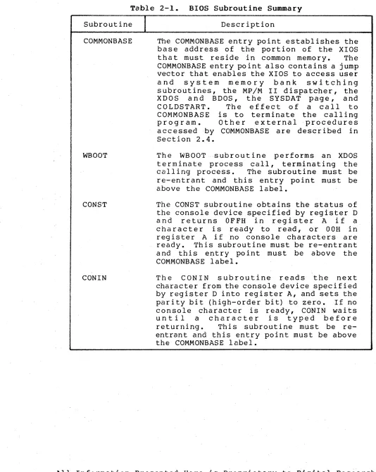
Table 2-1. BIOS Subroutine Summary
Subroutine
I
COMMONBASE
WBODT
CONST
CONIN
Description
The COMMONBASE entry point establishes the base address of the portion of the XIOS
that must reside in common memory. The
COMMONBASE entry point also contains a jump vector that enables the XIOS to access user
and system memory bank switching
subroutines, the MP/M II dispatcher, the
XDOS and BDOS, the SYSDAT page, and
COLDSTART. The effect of a call to
COMMONBASE is to terminate the calling
pro g ram. 0 the r e x t e rna I pro c e d u res accessed by COMMONBASE are described in Section 2.4.
The WBOOT subroutine performs an XDOS
te rminate process call, terminating the
calling process. 'I'he subroutine must be
re-entrant and this entry point must be above the COMMONBASE label.
The CONST subroutine obtains the status of the console device specified by register D
and returns OFFH in register A if a
character is ready to read, or OOH in
register A if no console characters are
ready. This subroutine must be re-entrant
a nd this entry po int must be above the COMMONBASE label.
The CONIN subroutine reads the next
character from the console device specified by register D into register A, and sets the parity bit (high-order bit) to zero. If no console character is ready, CONIN waits
until a character is typed before
returning. This subroutine must be
[image:26.612.45.579.58.728.2]MP/M II System Guide 2.2 BIOS Device Characteristics
Subroutine
I
CON OUT
LIST
PUNCH
READER
HOME
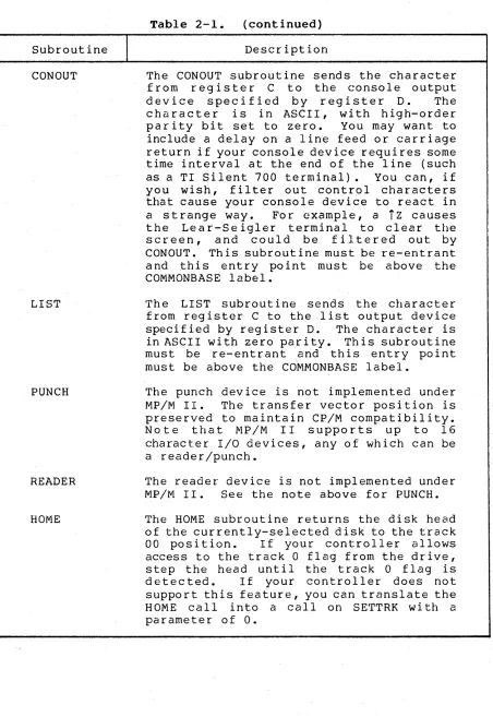
Table 2-1. (continued) Description
The CONOUT subroutine sends the character from register C to the console output de vic e s p e c i fie d by reg i s t e rD. Th e character is in ASCII, with high-order parity bit set to zero. You may want to include a delay on a line feed or carriage return if your console device requires some time interval at the end of the line (such as a TI Silent 700 terminal). You can, if you wish, filter out control characters that cause your console device to react in a strange way. For example, a
Tz
causes the Lear-Seigler terminal to clear the screen, and could be f i]. tered out by CONOUT. Th is subroutine must be roe-entrant and this entry point must be above the COMMONBASE label.'rhe LIST subrout ine sends the character from register C to the list output device specified by register D. The character is in ASCII with zero parity. This subroutine must be re-entrant and this entry point must be above the Co'MMONBASE label.
The punch device is not implemented under MP/M II. The transfer vector position is preserved to maintain CP/M compatibility. Note that MP/M II supports up to 16
character I/O devices, any of which can be
a reader/punch.
The reader device is not implemented under MP/M II. See the note above for PUNCH.
The HOME subroutine returns the disk head of the currently-selected disk to the track
00 position. If your controller allows access to the track 0 flag from the drive, step the head until the track 0 flag is detected. If your controller does not support this feature, you can translate the HOME call into a calIon SETTRK wi th a parameter of
o.
All Information Presented Here is Proprietary to Digital Research
[image:27.612.39.491.49.706.2]MP/M II System Guide 2.2 BIOS Device Characteristics
Subroutine
I
SELDSK
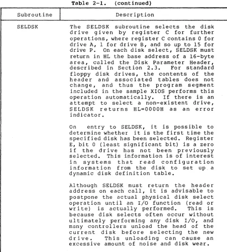
Table 2-1. (continued)
Description
The SELDSK subroutine selects the disk d r i ve g i ve n by reg i s t e r C for f u [' the r operations, where register C contains 0 for drive A, 1 for drive B, and so up to 15 for
drive P. On each disk select, SELDSK must
return in HL the base address of a 16-byte a rea, called the Disk Parameter Header,
described in Section 2.3. For standard
floppy disk drives, the contents of the he a d e r a n d ass 0 cia ted tab 1 e s doe s no t
change, and thus the program segment included in the sample XIOS performs this
operation automatically. If there is an
attempt to select a non-existent drive,
SELDSK returns HL=OOOOH as an error
indicator.
On entry to SELDSK, it is possible to
determine whether it is the first time the specified disk has been selected. Register E, bit 0 (least significant bit) is a zero if the dr ive has not been proeviously selected. This information is of interest in systems that read configuration information from the disk to set up. a dynamic disk definition table.
Al though SELDSK must return the heade r address on each call, i t is advisable to postpone the actual physical disk select operation until an I/O function (read or
write) is actually performed. This is
because disk selects often occur without ultimately performing any disk I/O, and many controllers unload the head of the current disk before selecting the new
drive. This unloading can cause an
excessive amount of noise and disk wear.
[image:28.617.119.572.62.563.2]MP/M II System Guide 2.2 BIOS Device Characteristics
Subrout ine
I
SETTRK
SETSEC
SETDMA
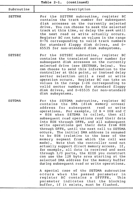
Table 2-1. (continued)
Description
For the SE'l"TRK subroutine, register BC contains the track number for subsequent disk accesses on the currently selected drive. You can choose to seek the selected track at this time, or delay the seek until the next read or wri te actually occurs. Register BC can take on values in the range 0-76 corresponding to valid track numbers for standard floppy disk drives, and 0-65535 for non-standard disk subsystems.
For the SETSEC subroutine, register BC contains the translated sector number for subsequent disk accesses on the currently
selected drive (see SECTRAN, below). You
can choose to send this information to the controller at this point, or instead delay
sector selection until a read or write
operation occurs. Register BC can take on
values in the range 1-26 corresponding to valid sector numbers for standard floppy disk drives, and 0-65535 for non-standard disk subsystems.
For the SET DMA sub r 0 uti n e , reg i s t e r BC
contains the DMA (disk memory access)
address for subsequent read or write
operations. For example, if B
=
OOH and C= 8 0 H w hen S E TD MA i s e a 11 ed, the n a I l subsequent read operations read their data into 80H through OFFH, and all subsequent write operations get their data from 80H through OFFH, until the next call to SETDMA occurs. The initial DMA address is assumed to be 80H (relative to the base of the memory segment from which the call was
made). Note that the controller need not
actually support di rect memory access. If, for example, all data is received and sent through I/O ports, the XIOS you construct can use the 128 byte area starting at the selected DMA address for the memory buffer during subsequent read or write operations.
A special case of the SETDMA subroutine
occurs when the passed parameter in
reg i s t e r B C con t a ins a 0 F F F F H • Th is parameter indicates that the blocking buffer, if i t exists, must be flushed.
All Information Presented Here is Proprietary to Digital Research
[image:29.615.46.490.63.722.2]MP/M II System Guide 2.2 BIOS Device Characteristics
Subroutine
I
READ
Table 2-1. (continued)
Description
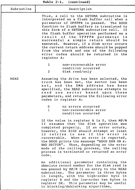
Thus, a call to the SETDMA subroutine is interpreted as a flush buffer call when a
parameter of OFFFFH is passed. The BDOS
function to flush buffers is translated to
this form of a SETDMA subroutine call. If
the flush buffer operation performed as a
r e s u l t of the OFFFFH parameter is
successful a simple return should be
executed. However, if a disk error occurs
the current return address should be popped from the stack and one of the following error codes should be returned in the register A:
1 non-recoverable error
condition occurred
2 disk read/only
Assuming the drive has been selected, the track has been set, the sector has been
s e t , and the DMA address has been
specified, the READ subroutine attempts to
read one sector based upon these
parameters, and returns the following error codes in register A:
a
no errors occurred1 non-recoverable error
condition occurred
If the value in register A is 0, then MP/M I I ass urn e s t hat the dis k 0 per at ion was
completed properly. If an error occurs,
however, the XIOS should attempt at least
10 retries to see i f the error is
r e co v era b 1 e • Wh en an err 0 r i s r e po r ted,
the BDOS prints the message "BDOS ERR ON x: BAD SECTOR". Then, depending on the error mode of the calling process, the calling process is terminated or returned an error code.
An additional parameter containing the
absolute record number for the disk read is now passed by MP/M II on entry to the READ
subroutine. The parameter is three bytes
in length, with the high-order byte in register B and the low-order two bytes in
register DE. This parameter may be useful
[image:30.615.116.570.63.698.2]MF/M II System Guide 2.2 BIOS Device Characteristics
. Subr.out ine
I
+---WRITE
Table 2-1 • (continued)
Description
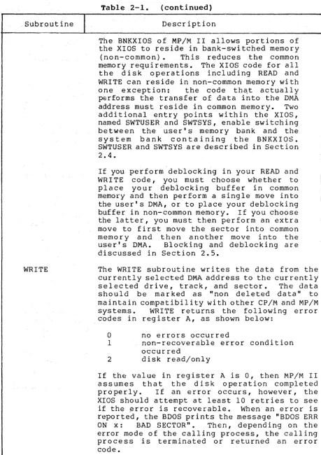
The BNKXIOS of MP/M II allows portions of the XIOS to reside in bank-switched memory
(non- common) • Th is reduces the common
memory requirements. The XIOS code for all the disk operations including READ and WRITE can reside in non-common memory with
one exception: the code thC\t actually
performs the transfer of data into the DMA
address must reside in common memory. Two
additional entry points within the XIOS, named SWTUSER and SWTSYS, enable switching between the user's memory bank and the system bank containing the BNKXIOS. SWTUSER and SWTSYS are described in Section 2.4.
. ,
If you perform deblocking in your READ and WRITE code, you must choose whether to p I ace you r deb I 0 c kin g b u f fer i n c 0 mmo n
memory and then perform a single move into the user's DMA, or to place your deblocking
buffer in non-common memory. If you choose
the latter, you must then perform an extra move to first move the sector into common memory and then another move into the us e r 's DMA • B 10 c kin g and deb 10 c kin g a r e discussed in Section 2.5.
The WRITE subroutine writes the data from the cur rently selected DMA address to the cur rentl y
selected drive, track, and sector. The data
should be marked as "non deleted data" to maintain compatibility with other CP/M and MP/M
systems. WRITE returns the followi ng error
codes in register A, as shown below:
o
no errors occurredI non-recoverable error condition
occurred
2 disk read/only
If the value in register A is 0, then MP/M II assumes that the disk operation completed
properly. If an error occurs, however, the
XIOS should attempt at least 10 retries to see
if the ~rror is recoverable. When an error is
reported, the BDOS prints the message "BDOS ERR
ON x: BAD SECTOR". Then, depend ing on the
error mode of the calling process, the calling process is terminated or returned an error code.
All Information Presented Here is proprietary to Digital Rese~rch
[image:31.617.40.500.61.712.2]MP/M II System Guide 2.2 BIOS Device Characteristics
Table 2-1. (continued)
Subroutine
I
DescriptionLISTST
SECTRAN
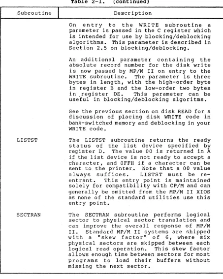
On entry to the WRITE subroutine a
parameter is passed in the C register which is intended for use by blocking/deblocking algorithms. rrhis parameter is described in Section 2.5 on blocking/deblocking.
An additional parameter containing the absolute record number for the disk write is now passed by MP/M lIon entry to the
WRITE subroutine. The parameter is three
bytes in length, with the high-order byte in register B and the low-order two bytes
in ,register DE. This parameter can be
useful in blocking/deblocking algoritms.
See the previous section on disk READ for a discussion of placing disk WRITE code in bank-swi tched memory and deblocking in your WRITE code.
The LISTST subroutine returns the ready status of the list device specified by
register D. The value 00 is returned in A
if the list device is not ready to accept a
character, and OFFH if a character can be
sent to the printer. Note that a 00 value
always suffices. LISTST must be
re-entrant. This entry point is maintained
solely for compatibility with CP/M and can generally be omitted from the MP/M II XIOS as none of the standard utilities use this entry point.
The SECTRAN subroutine performs logical sector to physical sector translation and can improve the overall response of MP/M
II. Standard MP/M II systems are shipped
with a "skew factor" of 6, where six physical sectors are skipped between each
logical read operation. This skew factor
[image:32.617.117.571.62.629.2]MP/M II System Guide 2.2 BIOS Device Characteristics
Subroutine
I
Table 2-1. (continued)
Description
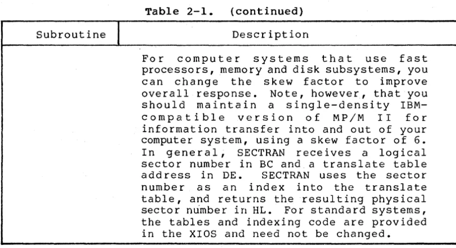
For computer systems that use fast processors, memory and disk subsystems, you can change the skew factor to improve
overall response. Note, however, that you
should maintain a single-density
IBM-compatible version of MP/M II for
information transfer into and out of your computer system, using a skew factor of 6. I n g e n era 1, S E CTRAN r e c e i v e s a l 0 g i cal
sector number in BC and a translate table
add ress in DE. SECTRAN uses the sector
number as an index into the translate table, and returns the resulting physical
sector number in HL. For standard systems,
the tables and indexing code are provided in the XIOS and need not be changed.
2.3 BIOS Disk Definition Tables
This section presents the organization and construction of tables within the BIOS that define the characteristics of a
particular disk system used with MP/M II. These tables can be
either hand-coded or automatically generated using the DISKDEF
utility provided with MP/M II. The elements of these tables are
presented below.
2.3.1 Disk Parameter Table Format
In general, each disk drive has an associated (16-byte) Disk Parameter Header which both contains information about the disk drive and provides a scratchpad area for certain BDOS operations. The format of the Disk Parameter Header for each drive is shown below.
Disk Parameter Header
XLT 0000 0000 0000 DIRBUE' DPB CSV ALV
16b 16b 16b 16b 16b 16b 16b 16b
Each element is a word (16-bit) value. The meaning of each Disk
Parameter Header (DPH) element is given in Table 2-2.
All Information Presented Here is 'Proprietary to Digital Research
[image:33.617.37.495.52.301.2]MP/M II System Guide 2.3 BIOS Disk Definition Tables
Table 2-2. Disk Parameter Header Elements
Element
I
Descr iptionXLT Offset of the logical to physical translation vector,
if used for this particular drive, or the value OOOOH
0000
DIRBUF
DPB
if no sector translation takes place (i.e, the
physical and logical sector numbers are the same). Disk drives with identical sector skew factors share the same translate tables.
Scratchpad values for use within the BDOS (initial value is unimportant).
Offset of a 128 byte scratchpad area for directory
operations wi thin BDOS. All DPHs address the same
scratchpad area. The same DIRBUF is used by all
drives.
Offset of a disk parameter block for this drive. Drives with identical disk characteristics address the same disk parameter block.
CSV Offset of a scratchpad area used for software check for
changed disks. This offset is different for each DPH.
ALV Offset of a scratchpad area used by the BDOS to keep
disk storage allocation information. This offset is
different for each DPH.
Given n disk drives, the DPHs are arranged in a table whose first row of 16 bytes corresponds to drive 0, with the last row
corresponding to drive n-1. The table thus appears as:
DPBASE
00 XLT 00 0000 0000 0000 DIRBUF DBP 00 CSV 00 ALV, 00
01 XLT 01 0000 0000 0000 DIRBUF DBP 01 CSV 01 ALV 01
n-1 XLTn-1 0000 0000 0000 DIRBUF DBPn-1 CSVn-1 ALVn-1
where the label DPBASE defines the offset of the DPH table relative to the beginning of the operating system.
A responsibility of the SELDSK subroutine, defined in the previous section, is to return the offset of the DPH from the
beginning of the operating system for the selected drive. The
MP/M II System Guide 2.3 BIOS Disk Definition Tables
NDISKS SELDSK:
EQU 4 ;NUMBER OF DISK DRIVES
;SELECT DISK N
LXI H,OOOOH
MOV A,C
CPI NDISKS
RNC
MOV L,C
GIVEN BY C
;READY FOR ERR
;N BEYOND MAX DISKS? ;RETURN IF SO
;0
<=
N<
NDISKSDAD H ;READY FOR
*
16DAD H
DAD H
DAD H
LXI D,DPBASE
DAD D ;DPBASE + N
*
16RET
The translation vectors (XLT 00 through XLTn-l) are located
elsewhere in the BIOS, and simply correspond one-for-one with the
logical sector numbers zero through the sector count-I. The Disk
Parameter Block (DPB) for each drive is more complex. A particular
DPB, which is addressed by one or more DPHs, takes the general form:
SPT BSH BLM EXM DSM DRM ALO ALI CKS OFF
16b 8b 8b 8b 16b 16b 8b 8b 16b 16b
where each is a byte or word value, as shown by the "8b" or "16b"
indicator below the field. The fields are defined in Table 2-3.
All Information Presented Here is Proprietary to Digital Research
MP/M II System Guide 2.3 BIOS Disk Definition Tables
Table 2-3. Disk Parameter Block Fields
Field
I
DefinitionSPT is the total number of sectors per track.
BSH is the data allocation block shift factor,
determined by the data block allocation size.
BLM is the block mask which is also determined by the
data block allocation size.
EXM is the extent mask, determined by the data block
allocation size and the number of disk blocks.
DSM determines the total storage capacity of the disk
drive.
DRM determines the total number of directory entries
which can be stored on this drive.
ALO,ALI determine reserved directory blocks.
CKS is the size of the directory check vector, a CKS of
8000H marks the drive as permanent with no directory records checked.
OFF is the number of reserved tracks at the beginning
of the (logical) disk.
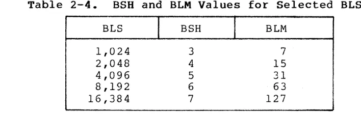
Although these table values are produced automatically by DISKDEF, it is worthwhile reviewing the derivation of each field so that the
values may be cross-checked when necessary. The values of BSH and
BLM determine (implicitly) the data allocation size BLS, which is
not an entry in the disk parameter block. Given that you have
sele~ted a value for BLS, the values of BSH and BLM are shown in
Table 2-4 below, where all values are in decimal.
Table 2-4. BSH and BLM Values for Selected BLS
BLS
I
BSHI
BLM1,024 3 7
2,048 4 15
4,096 5 31
8,192 6 63
16,384 7 127
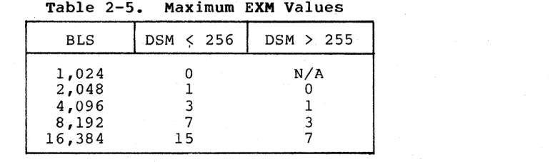
[image:36.612.118.575.63.406.2] [image:36.612.148.502.526.638.2]MP/M II System Guide 2.3 BIOS'Disk Definition Tables
Table 2-5. Maximum EXM Values
BLS IDSM <;: 256
I
DSM>
2551,024 2,048 4,096 8,192 16,384
o
1 3
7
15
N/A
o
1 3
7
The value of DSM is the maximum data block number supported by this particular drive, measured in BLS units. The product BLS times
(DSM+l) is the total number of bytes held by the drive and, of
course, must be within the capacity of the physical disk, not counting the reserved operating system tracks.
The DRM entry is one less than the total number of directory
entries, which can take on a 16-bit value. The values of ALO and
ALl, however, are determined by DRM. The two values ALO and ALI can
together be considered a string of 16-bits, as shown below.
ALO ALI
00 01 02 03 04 05 06 07 08 09 10 11 12 13 14 15
where position 00 corresponds to the high-order bit of the byte labeled ALO, and 15 corresponds to the low-order bit of the byte
labeled ALI. Each bit position reserves a data block for a number
of directory entries, thus allowing a total of 16 data blocks to be
assigned for dir~ctory entries (bits are assigned starting at 00 and
f i l l e d t 0 the rig h t un t i l po sit ion 15). E a c h d ire c to r y e n try occupies 32 bytes, as shown in Table 2-6.
Table 2-6. BLS and Number of Directory Entries
BLS
I
Directory Entries1,024 32 times # bits
2,048 64 times =It bits
4,096 128 times
#
bits8,192 256 times
#
bits16,384 512 times # bits
Th us, i f D RM = 127 ( 128 d ire c tor yen t r i e s), and B LS = 10 24, the n there are 32 directory entries per block, requiring 4 reserved
blocks. In this case, the 4 high-order bits of ALO are set,
resulting in the values ALO = OFOH and ALI = OOH.
All Information Presented Here is Proprietary to Digital Research
[image:37.612.125.512.63.177.2] [image:37.612.66.461.497.620.2]MP/M II System Guide 2.3 BIOS Disk Definition Tables
The CKS value is determined as follows: if the disk drive
media is removable, then CKS
=
(DRM+l)/4, where DRM is the lastdirectory entry number. If the media is fixed, then set CKS
=
8000H(no directory records are checked in this case and drive marked as permanent) •
Finally, the OFF field determines the number of tracks which
are skipped at the beginning of the physical disk. This value is
automatically added whenever SETTRK is called, and can be used as a mechanism for skipping reserved operating system tracks, or for partitioning a large disk into smaller segmented sections.
To complete the discussion of the OPB, recall that several DPHs
can address the same OPB if their drive characteristics are
identical. Further, the DPB can be dynamically changed when a new
drive is addressed by simply changing the pointer in the DPH since the BOOS copies the DPB values to a local area whenever the SELDSK function is invoked.
Returning back to the DPH for a particular drive, note that the
two address values CSV and ALV remain. Both addresses reference an
area of uninitialized memory following the BIOS. The areas must be
unique for each drive, and the size of each area is determined by the values in the DPB.
The size of the area addressed by CSV is CKS bytes, which is sufficient to hold the directory check information for this
particular drive. If CKS = (DRM+l)/4, then you must reserve
(DRM+l)/4 bytes for directory check use. If CKS
=
0, indicating nochecked directory entries, or CKS
=
8000H, marking the drive aspermanent with no checked directory entries, then no storage is reserved.
The size of the area addressed by ALV is determined by the maximum number of data blocks allowed for this particular disk, and
is computed as (DSM/8)+1.
2.3.2 The DISKDEF Macro Library
A macro library called DISKOEF greatly simplifies the table
cons t ruc t ion process. You must have access to the MAC macro
assembler or the RMAC relocatable macro assembler distributed with MP/M II to use the DISKDEF facility. The macro library is included with all MP/M II distribution disks.
MP/M II System Guide 2.3 BIOS Disk Definition Tables
MACLIB DISKDEF
. .
. . .
DISKS n
DISKDEF
o , •••
DISKDEF 1 , •••
DISKDEF n-l
.
. .
.
.
ENDEF
where the MACLIB statement loads the DISKDEF.LIB file (on the same disk as your BIOS) into MAC's internal tables. The DISKS macro call follows, which specifies the number of drives to be configured with your system, where n is an integer in the range 1 t o l 6 . A series of DISKDEF macro calls then follow, which define the characteristics of each logical disk, 0 through n-l (corresponding to logical drives
A through P). Note that the DISKS and DISKDEF macros generate the
in-line fixed data tables described in the previous section, and thus must be placed in a non-executable portion of your BIOS, typically directly following the BIOS jump vector.
The remaining portion of your BIOS is defined following the DISKDEF macros, with the ENDEF macro call immediately preceding the
END statement. The ENDEF (End of Diskdef) macro generates the
necessary uninitialized RAM areas that are located in memory above your BIOS.
where
The form of the DISKDEF macro call is
DISKDEF dn,fsc,lsc, [skf] ,bls,dks,dir,cks,ofs, [k16], [prm]
dn is the logical disk number, 0 to n-l
fsc is the first physical sector number (0 or 1)
lsc is the last sector number
skf is the optional sector skew factor
bls is the data allocation block size
dks is the total number of blocks on the drive.
dir is the number of directory entries
cks is the number of "checked" directory entries
ofs is the track offset to logical track 00
k16 is an optional 1.4 compatibility flag which
forces 16K/directory entry
prm is an optional flag which indicates that the
drive is permanent (cannot be removed)
The value dn is the drive number being defined with this
DISKDEF macro invocation. The fsc parameter accounts for differing
sector numbering systems, and is usually 0 or 1. The lsc is the
last numbered sector on a track. When present, the skf parameter
defines the sector skew factor which is used to create a sector
translation table according to the skew. If the number of sectors
is less than 256, a single-byte table is created, otherwise each
All Information Presented Here is Proprietary to Digital Research