I
i· ¥WEl.1.
. . . .
..-CP-6
SUBJECT
CP-6
OPERATIONS REFERENCE
MANUAL
Description of Operations Environment Including Operator Key-ins and
Messages Sent to Operator Consoles
SOFTWARE SUPPORTED
Operating System COO.
ORDER NUMBER
CE34-03
March 1985
Preface
This document is a reference manual for the
cee
version of the Honeywel I CP-6 Operating System. It is organized in encyclopedic fashion for ease of reference with the keyinslisted in alphabetical order and is not intended to be guide-like or tutorial.
The specific subset of operations procedures used at any particular CP-6 installation should be documented by the system manager and made avai lable to the operations staff.
The Los Angeles Development Center (L.A.D.C.) of Honeywel I Information Systems Inc. has developed Computer Aided Publ ications (CAP). CAP is an advanced document processing system providing automatic table of contents, automatic indexing. format control.
integrated text and graphics. and other features. This manual is a product of CP-6 CAP.
Readers of this document may report errors or suggest changes through a STAR on the CP-6 STARLOG system. Prompt response is made to any STAR against a CP-6 manual. and changes wi I I be incorporated into subsequent releases and/or revisions of the manuals.
The information in this publ ication is bel ieved to be accurate in al I respects. Honeywel I Information Systems cannot assume responsibi I ity for any consequences
resulting from unauthorized use thereof. The information contained herein is subject to change. New editions of this publ ication may be issued to incorporate such changes.
The information and specifications in this document are subject to change without notice. This doc· ument contains information about Honeywell products or services that may not be available out· side the United States. Consult your Honeywell Marketing Representative.
©Honeywell Information Systems Inc., 1985 File No.: 1 W13
Preface
Table of Contents
Section 1. The CP-6 Operations Environment Introduction . . . .
Terminology . . . . System Operation Unattended Operation Attended Operation Overview of Consoles
Console Attributes
Administrative Console Attributes Communications Console Attributes Device Console Attributes
System Console Attributes
Transaction Processing Console Attributes Console Security . . . .
Console Hardware Types . . . . IOM-CONNECTED Consoles
Low Cost Console (LCC) System Control Console (SCC) FEP Connected Console (FCC) IRBT Control Console (ICC) Console Ghosts . . . . HELP Foci I i ty . . . . Other Facets of Operations
AI ignment of Output Symbiont Devices Concurrent Output Mode . . . . Section 2. System Start-up and Recovery
Ove rv i ew . . . .
Organization Of The Honeywel I-Supplied PO Tape Set Tape Boot Concepts and Processes
PO Tape . . . . Initiating Tape Boot Aardvark and TIGR Ghost 1 . . . .
Startup Process Patching . . . .
Disk Boot Concepts and Processes The DINGO Ghost . . . . Boot Ope rat ions . . . .
Default Assumptions Concerning Device Assignments Default Assumptions Concerning Reading Of Patches Details of the Boot Process
Boot Scenarios For Specific Tasks Boot Tape Creation via DEF
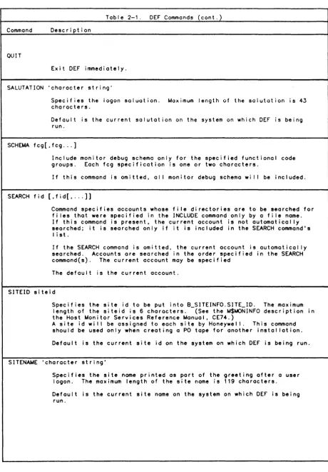
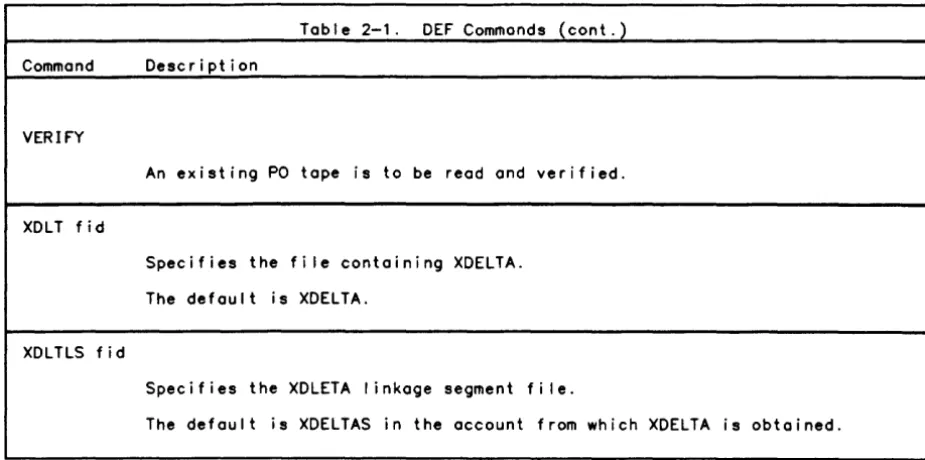
The DEF Process . . . . Unlabled Portion of the PO Tape Set Labeled Portion of the PO Tape Set DEF Invocation
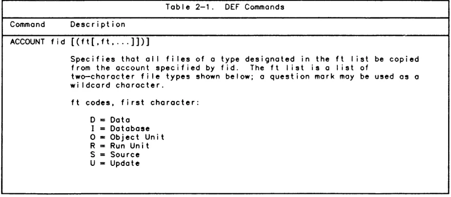
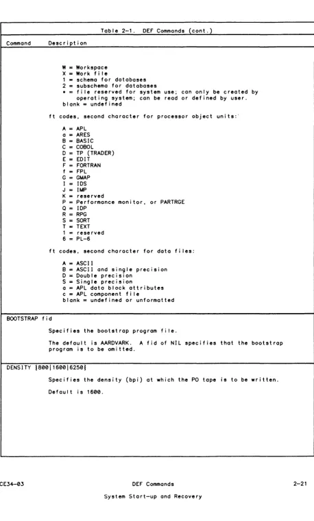
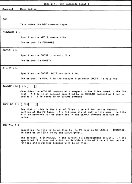
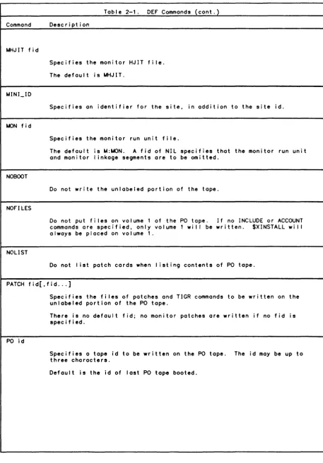
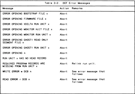
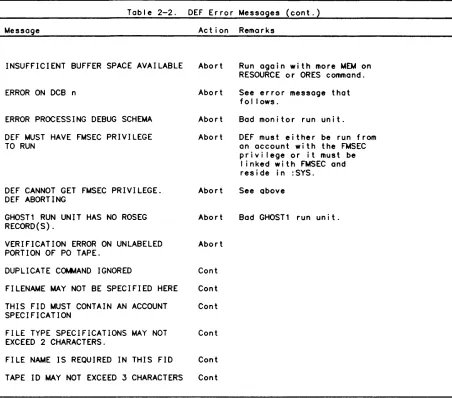
DEF Commands Sample DEF Job Error Reporting Recovery . . . . .
Automatic Recovery
Automatic Recovery Messages Fu I I Recove ry
Operator Recovery
CE34-03 Table of Contents
FEP Recovery System Shutdown
Section 3. The KEYIN Processor Introduction
iv
KEYIN Groups
General Console Keyins
System Control Keyins Special System Keyins User Control Keyins
General Device Keyins
Tape Drive Keyins Disk Drive Keyins
Unit Record Device Keyins Queue Control Keyins Job Display Keyins Communications Keyins Diagnostic Keyins Console Ghost Keyins
Informational Keyins
~essage Sending Keyins
Transaction Processing Keyins Comgroup Processing Keyins Keyin Components
CP-6 Operator Keyins Omasternome Keyin
? Keyin
?? Keyin ABORT Keyin ACCTLG Keyin ALIGN Key i n ANSSCRATCH Keyin AUTO SCHEDULING Keyin
AUTO SCHEDULING ~ESSAGE Keyin AUTO SCHEDULING UPDATE Keyin B: Keyin . . .
BATCH Keyin
BATCH ON/OFF Keyin BOOT FEP Keyin BROADCAST Keyin BYE Keyin CANREAD Keyin CANT MOUNT Keyin CANT OVER Keyin CANT RING Keyin CONSOLE STATUS Keyin CONSOLES Keyin CONTINUE Keyin CPU Keyin CPUS Keyin CRASH FEP Keyin DATE Keyin
DELETE INPUT Keyin DELETE INPUT ALL Keyin DELETE OUTPUT Keyin DELETE OUTPUT ALL Keyin DELETE OUTPUT ALL FOR~ Keyin DELTA Keyin
DEVICES Keyin DIAG Keyin DIE! Keyin
DISABLE LINES Keyin DISCONNECT TER~INAL Keyin DISK Keyin . . . . DISMOUNT Keyin DISPLAY sysid Keyin DISPLAY ALL Keyin
Table of Contents
DISPLAY DEFER Keyin DISPLAY INPUT Keyin DISPLAY NORUN Keyin DISPLAY NSFORM Keyin DISPLAY OUTPUT Keyin DISPLAY PRIO Keyin DISPLAY RUNNING Keyin DUMP FEP Keyin
E FEP Keyin E Keyin ENABLE Keyin ERROR Keyin ERSEND Keyin EXCLMOUNT Key i n F: Keyin
FEPS Keyin FIRMLOAD Keyin FLUSH Keyin FORM ON Keyin G: Keyin GHOST Keyin HEADER Keyin HELP Keyin HISTORY Keyin HOSTS Keyin
INFO Keyin KILL Keyin LINKS Key i n LOAD Keyin LOCK Keyin LPWSN Keyin MAKE CPU Keyin MAKE RESOURCE Keyin MAKE SYMBIONT Keyin MASTERS Keyin MOUNT Keyin MSG Keyin
MYREADACCT Keyin NATLANG Keyin NCTL Keyin
NETWORK ROUTE Keyin NODIAG Keyin
NODES Keyin NOUSERSI Keyin OCHIST Keyin OFF Keyin ON Keyin ON BA Keyin ON GH Keyin ON TP Keyin ON TS Keyin OVER Keyin PENDING Keyin PRIO INPUT Keyin
PRIO INPUT ALL Keyin . PRIO OUTPUT sysid Keyin PRIO OUTPUT .account Keyin PRIO OUTPUT ALL Keyin PROCEED Keyin
PROF! LE Key in PUBLIC Key i n PWIDTH Keyin QUIET Keyin READ$ Keyin READ Keyin READACCT Keyin
CE34-03 Table of Contents
REPRINT Keyin REQUEST Keyin RERUN Keyin RERUN ALL Keyin RESERVE Keyin RESTRICT Keyin RETRY Keyin RING Keyin ROUTE FROM Keyin ROUTE INTO Keyin S Keyin
SAVE Keyin SCRATCH Keyin SEND Keyin SENDALL Keyin SENDFEP Keyin SET Keyin SETS Keyin SETUP Keyin SHARE Keyin SPACE Keyin START Keyin START CPU Keyin START FEP Keyin START FEPS Keyin START TP Keyin STARTUP!! Key i n STATION Keyin STOP CPU Keyin STOP FEP Keyin STOP FEPS Keyin SUSPEND Keyin SWITCH OUTPUT Keyin
SWITCH OUTPUT .account Keyin SWITCH OUTPUT ALL Keyin SWITCH OUTPUT FORM Keyin SWITCH OUTPUT sysid Keyin SYMB INPUT Keyin
SYMB OUTPUT Keyin sysid: Keyin TAPES Keyin TELL Keyin TELLALL Keyin TERMINAL Keyin TERMINALS Keyin TERMINAL ON Keyin TIME Keyin
TIME ON/OFF Keyin TP/ Keyin
TURNOVER Keyin UC Keyin
UNRESERVE Keyin UNRESTRICT Keyin UNROUTE Keyin USERS Keyin VOLUMES Keyin X Keyin
X CONSOLE Keyin X FEP Keyin XDELTA Keyin Y: Keyin ZAP! Keyin ZAP!! Key i n
Section 4. Console Message Overview Introduction
Nu I I Messages
vi Table of Contents
Information ~essages
Device Status ~essages
Operational ~essages ~ount Activity ~essages
System Problem ~essages
Device Error ~essages
Section 5. Labeling ~agnetic Topes via LABEL Introduction . . . .
Tope Security Levels Commands . . . .
LABEL Command SEQUENTIAL Command SCRATCH Command REMOVE Command Confirmation ~essages
Confirmation ~essages for SEQUENTIAL Command Error ~essages . . . .
Appendix A. Configurations General Operating Procedures
Safety Precautions . . . . Turning Equipment Off and On
Central System Units, Console, Peripheral Processors Peripheral Units . . . .
Central Processor (For DPS-B and DPS-C Systems) Left CPU Panel
Right CPU Panel SCU Switch Settings . IOM/ICU Switch Settings Left Side . . . . . Right Side . . . . . Front-End Processor Appendix B. KEYIN Summary
Appendix C. ~onitor Service Error ~essages
Appendix D. RECOVERY Error ~essages and SCREECH Codes Error Reporting . . . .
Recovery Errors . . . . . Single User Abort Fai lures Recovery Dump Fai lure Recovery Fai lure
SCREECH CODE Descriptions
Appendix E. Rules for Tope and Disk Usage Tope Usage . . . . . . . . . Di sk Usage . . . . . . . . . . .
Appendix F. Related Publ ications for Peripheral Devices Appendix G. FEP-Connected Unit Record Peripherals
Tables:
Table 2-1. Table 2-2. Tab I e A-1. Table A-2. Table A-3. Tab I e C-1. Table 0-1.
CE34-03
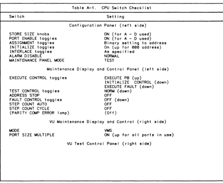
DEF Commands . . . DEF Error ~essages . . CPU Switch Checklist. SCU Switch Checklist.
IOM/ICU Switch Checkl ist . .
~onitor Service Errors (AI I SCREECH Codes . . . .
.
. . . .
~essages)Table of Contents
4-1 4-2 4-2 4-2 4-3 4-4 5-1 5-1 5-1 5-2 5-2 5-3 5-4 5-4 5-5 5-6 5-6 A-1 A-1 A-1 A-1 A-1 A-2 A-2 A-2 A-3
A-5
A-7 A-7 A-7A-9
B-1 C-1 0-1 0-1 0-1 0-2 0-2 0-3 0-3 E-1 E-1 E-3 F-1 G-1 2-20 2-26 A-4 A-6A-8
C-1 0-3About This Manual
This manual discusses the operator's role in relation to CP-6 system operation. The manual is organized in the following fashion:
Section 1 describes the CP-6 operations environment, with descriptions of different types of operator consoles. A new subsection, AI ignment of Output Symbiont Devices, has been added for the C00 release.
Section 2 describes the procedure for system booting (start-up), orderly shutdown, and recovery.
Section 3 describes the keyins that are issued from the operator console. Keyins are special commands to the system that the operator issues to guarantee system integrity and service to the users.
Section 4 describes the types of messages that may be sent by the system or by the users of the system to the operator console.
Section 5 discusses labeling of magnetic tapes.
Appendix A describes the hardware configurations for the CPU and front-end devices. The ADDRESS 10M BASE switch settings and INTERRUPT BASE switch settings have been changed
for the C00 release.
Appendix B is a summary of keyin syntax.
Appendix C gives a list of ~on i tor Service error messages.
Appendix D gives a list of recovery error messages and screech codes.
Appendix E gives rules for tape and disk handl ing.
Appendix F is a list of related publ icat ions for supported peripheral devices.
Appendix G gives information concerning FEP connected unit record peripherals.
Notation Conventions
Notation conventions used in command specifications and examples are I isted in the Notation Conventions table below.
Notation Description
CAPITAL LETTERS
Capitol letters must be entered as shown for input, and wilt be printed as shown in output.
lowercase letters
Lowercase letters identify on element that must be replaced with a user-selected value.
AP i could be entered as AP 2.
Special Characters
Brackets
Numbers that appear on the I ine (i.e., not subscripts), special symbols, and underl ines appear as shown in output messages and must be entered as shown when input.
Ixxx could be entered as 1011.
An element inside brackets is optional. Several elements separated by on "or" bar inside a pair of brackets means that the user may select anyone or none of those elements.
[key] means a key value may be entered.
When enclosing keywords, brackets signify that al I or port of the bracketed portion may be entered.
K[EY] can appear as K, KE, or KEY.
Braces and Or Bar
CE34-03
Elements placed inside a pair of braces identify a required choice. These are always used with the Or bar (I). The Or bar separates the elements in a required choice.
IAI idl - means that either the letter A or the value of id must be entered.
Notation
EI lips i s
Carated Letters
Keywords
Doub I e Quotes
Apostrophe
xii
(cont.)
Description
The horizontal el I ipsis indicates that a previous bracketed element may be repeated, or that elements hove been omitted.
option[,option]... - means that one or more options may be entered, with a comma inserted between each variable.
Letters inside carats indicate the keys on a physical terminal device.
<ESC> <8S> key.
means press the escape key and then the backspace
Note that the control key (shown as <CNTL» is simi lar to the shift key: it does nothing on its own, but changes the meaning of the keys that are hit whi Ie it is depressed.
Keywords can be typed in uppercase or lowercase or a combination of both. In this manual, keywords are always shown in uppercase.
Comments within command streams are denoted by being enclosed in double quotes marks (").
Strings that contain del imiters must be enclosed by apostrophes ('); if an apostrophe is part of a string, it is denoted by adjacent apostrophes (").
Section 1
The CP-6 Operations Environment
Introduction
In the CP-6 environment, operators are responsible for several functions:
o Maintaining system integrity, including fi Ie system maintenance.
o Monitoring system functions and keeping precise records.
o Responding to system and user operator requests.
o Alerting other specialists when hardware or software maintenance is required.
o Performing certain preventive maintenance.
Operating the CP-6 system and peripheral devices includes taking safety precautions to prevent injury to personnel or damage to the equipment. To avoid the possibi lity of serious injury to personnel, the operating staff must follow basic safety practices. No
informal or "emergency" practice should ever al low the operator to endanger personnel or expose the equipment to possible damage.
Operators must know the overal I configuration and understand how the equipment can be configured both before and whi Ie running the system. Setting of the hardware
configuration switches should be done under the direction of the field engineering staff or the installation manager. The settings of these switches are crucial to the
operation of the system; therefore, the settings should not be changed unless specifically authorized.
Operators assist in the preservation of the integrity of the CP-6 fi Ie management system. Copies of fi les or entire accounts are often periodically dumped onto tapes or disk packs as backup. In most cases, these tapes or disk packs must not leave the computer room or be processed by unauthorized personnel; otherwise, al I steps taken by the system to preserve the security of the information may be in vain.
Preventive maintenance reduces the frequency of operations difficulties. A regular schedule of preventive maintenance lowers the risk of hardware failure.
Naturally, instances may occur where the operators lack the experience to cope with a serious problem; in this case, they should request assistance from the installation manager or Honeywell Customer Service Representative.
Terminology
OPERATOR denotes a person responsible for the orderly runn~ng of a CP-6 system or for running a terminal (RBT) connected to a CP-6 system, and who IS responsible for
answering system requests for human intervention for control of the CP-6 system or te rm ina I.
KEYIN is the set of characters an operator types on a keyboard display device
(console) and transmits to the CP-6 system. The word "keyin" can also refer to the act of inputting and transmitting a message.
CE34-03 Terminology 1-1
MESSAGE a set of characters that the CP-6 system transmits to a console for display. (The message is what the CP-6 system says to the operator, the keyin is what the
operator says to the CP-6 system.)
CONSOLE one of severa! types of "conso!e" devices connected to the CP-6 system. The most general description of a console is any combination keyboard-display device that is capable of displaying messages of 80 or more characters in length, is capable of
generating keyins of 80 or more characters. and scrol Is automatically. For remote batch terminals (RBTs) with bui It~in keyboard~display devices, the keybocrd-displcy is the RBT console. For RBTs without such bui It-in devices, any device capable of being a CP-6 time-sharing terminal can be the console for that RBT.
CONSOLE ATTRIBUTE the characteristic of a console which determines what messages it wi I I display and what keyins it may perform. Attributes are given to a console when it
is created by the installation manager.
DEVICE a unit of communications hardware treated as a separate entity by the system. A time-sharing terminal is one device, as is the printer at an RBT.
TERMINAL a unit of communication hardware connected to the CP-6 system via one communication I ine. A keyboard display unit is typically a terminal as wei I as a device; an RBT is a terminal supporting several devices.
STATION denotes a group of devices under the control of, and including, a single device console. For example, an Intel I igent Remote Batch Terminal (IRBT), its devices, and its console constitute a station.
WORKSTATION (WSN) denotes the environment of devices made avai lable to a user. The CP-6 system qualifies al I requests for access to devices by a WSN designation, which is used to control access and to resolve addressing to an actual device.
System Operation
CP-6 system operation is separated into two phases: the startup and initial ization phase and the dai Iy monitoring and servicing that keeps the system running. The startup phase includes adjusting as necessary the equipment configuration controls, and
initial izing the system to give control to the system software. During the course of dai Iy system operation, I ittle operator action is required, with the exception of servicing the peripheral equipment and responding to special requests from the system and from the system's users.
Since the CP-6 system functions effectively with a minimum of operator intervention, operator action during dai Iy system operation is essentially maintaining service to users, primari Iy fil ling user requests to mount tapes, and the monitoring and servicing of peripherals.
System integrity checks normally detect if a system recovery ("screech") needs to be performed, and if so, what level of system recovery needs be performed. System initiated screeches normally proceed automatically, sending a screech code message to the operator console. If necessary, the operator can initiate an automatic recovery when it appears that the system is not running properly.
When the system encounters a problem with a peripheral device, it displays an error message to the console. For errors that are recoverable with operator assistance, the operator responds with a device keyin or corrects the malfunction (such as paper jams or paper replacement).
In addition to reporting errors on the operator's console, the system maintains a system error log fi Ie. This fi Ie contains a log of system and peripheral device fai lures that were corrected, that were irrecoverable, and that require operator assistance for
recovery.
The system has the capabi lity for maintaining records of all console transactions in the "console history fi Ie", for later access and review by the system manager, using the CP-6 system's REPLAY processor.
Unattended Operation
The CP-6 system supports two modes of operation: unattended and attended. unattended mode, no operator is present and the CP-6 system itself forbids requiring operator intervention or assistance. In attended mode, the CP-6 depending on user activity, request an operator's assistance in completing tasks. The system manager sets certain parameters using CONTROL and other processors to define the "unattended" state.
In
activities system can, certain CP-6 system
In general, unattended mode means that the CP-6 system activities that would require operator intervention are inhibited (i.e., the I ine printer and card punch are locked out, as are tape drives and other removable resource devices). During the unattended mode, users who require tape or disk mounts are informed that such devices are not avai lable (such activities cannot be completed because an operator is not physically present). As a result, if the CP-6 system is al lowed to run out of paper in the
printer, or request tape mounts, this condition would be considered attended by the CP-6 system regardless of whether there is a human in the computer room or not. It is the system manager's responsibility to define the condition of attended operation and unattended operation of the CP-6 system. In the event of a power failure, unattended recovery wi I I not take place.
Attended Operation
During the attended mode, the CP-6 system operator's functions are of the fol lowing types:
o Responsibi I ity items, requiring operator assistance and intervention to complete the job efficiently and correctly.
o Authority items, permitting an operator to perform the duties needed to guarantee system security and efficient throughput.
o Informational items, permitting an operator to see certain items in order to remain knowledgeable about the state of the CP-6 system.
As can be seen from the above discussion, a human operator is an important part of the CP-6 system. Although the CP-6 system can be used extensively in the unattended mode, many users require the assistance of an operator to effectively util ize the resources and features of the CP-6 system. The CP-6 system may request that a reel of tape be mounted on a tape drive for time-sharing use, or 0 disk pack set be mounted on certain
disk drives for a batch job's use. In these cases, the process that the time-sharing or batch user is executing is suspended, and cannot proceed until the requested mount is completed.
With this in mind, the operator must be considered to be an essential element in providing smooth, uninterrupted services to the users of the CP-6 system. Likewise, should a I ine printer run out of paper, the operator wil I be informed of the condition, and to keep the system running at its full capacity (and to ensure that a user will eventually receive his output), the operator is expected to correct the out-of-paper condition as quickly as possible.
The items a specific operator must perform in relation to a specific CP-6 system vary from site to site, and from day to day, and it is impossible for all such cases to be discussed here. The areas in which an operator has authority are determined by the system manager and enforced by the CP-6 system using console attributes. In general, authority items are those items that an operator can modify using personal judgment. These items may include altering the batch queue priorities, aborting users, or any number of items. The CP-6 system is always able to run without an operator exercising any of these authority items. They are provided to the operator to encourage security and efficient use of the CP-6 system.
CE34-03 Attended Operation 1-3
Informational items are, again, determined by a console's attributes, and are provided to the operator to give a "feel" of how the CP-6 system is running. Informational items can be useful in conjunction with authority items to help a system run more efficiently. Informational items avai lable at operator's consoles can be user logons and logoffs, tape usage, and batch queue contents and priorities.
Overview of Consoles
Operators consoles are a very powerful and versati Ie feature of the CP-6 system. Operator communication faci lities provide an operator with:
o Information about system activity.
o Information about devices which need attention.
o The abil ity to communicate with users, programs, and transaction processing administrators (TPAs).
o The abil ity to manipulate and control users and batch queues.
o Information about problems or potential problems within the system.
o The capabi I ity for multiple operator consoles per system.
o The abi I ity to use any device that can operate as a CP-6 time-sharing terminal as the CP-6 system console.
o Common input syntax for al I operator commands to the CP-6 system.
o Consoles that may be defined to have I imited scope and authority. Consoles can be associated with a particular group of users or devices, and thus can only receive
information about and/or control those users or devices. The console may be limited so that only information can be received. Control over individual users can
simi larly be restricted.
o Operator's consoles that may simultaneously execute programs as time-sharing terminals.
o The capability to use four types of hardware-configured consoles: the Low Cos. Console, the System Control Console, the FEP Connected Console, and the Ii T Control Console.
Console A ttribu tes
Console attributes determine the functional characteristics and capabi lities of the consoles connected to the CP-6 system. Each console has a set of INPUT attributes (which limit the set of val id keyins acceptable from that console) and a s~~ of OUTPUT attributes (which limit the set of valid messages that wi I I be printed at :t console, as wei I as I imiting the set of valid informational keyins).
There are five console attributes, which may be defined as either INPUT or OUTPUT or both, for any given console: ADMINISTRATIVE, COMMUNICATIONS, DEVICE, SYSTEM, and TP.
Consoles are authorized by the system manager for any combination of these attributes. The attributes of a currently active console may be displayed via the CONSOLE STATUS
keyin.
1-4 Console Attributes CE34-03
Administrative Console Attributes
Administrative consoles are associated with workstations (WSNs). An ADMINISTRATIVE INPUT console can modify the batch queue for its WSN. abort users with a matching workstation of origin (WOO). communicate with users of its WSN. and answer M$KEYINS of users whose WOO matches its WSN. An ADMINISTRATIVE OUTPUT console can. of course. only display those items concerned with its WSN. An ADMINISTRATIVE INPUT console is
sometimes referred to as a PADMIN console. An ADMINISTRATIVE OUTPUT console is sometimes referred to as a UADMIN console.
Communications Console Attributes
A console with communications attributes displays (OUTPUT) or modifies (INPUT) actions of communications equipment connected to the CP-6 system. Typical actions include activating IRST communications I ines in FEPs (commonly cal led synchronous communications
I ines. SYNC for short). displaying the status of an FEP connected to the CP-6 system, or communicating with remote master hosts when the CP-6 system is acting as a slave IRST to another system.
Device Console Attributes
A console with device attributes receives information about (OUTPUT) or controls (INPUT) one or more types of devices. depending in how the console's station is defined.
Devices are referred to by four character names from device consoles; the first two characters identify the device type (LP, CPt CR. DP. MT) fol lowed by a two-digit device number (01. 15, 99, etc.). (The CP-6 system identifies devices as the four character name plus the station name. However. operators at device consoles neither see nor need to type the station name, as a device console implicitly knows its station.) The CP-6 system may have many LP01's but each must be associated with a different station.
Therefore. if a console controls an LP01. it can only control that LP01. and none of the other LP01's on the system. Additionally. device consoles are al lowed to examine and manipulate the output queue for its station. providing such a queue exists.
A device console also receives information about or controls the MPC hardware that controls devices at its station. Typically MPC names are of the same format as device names. but use the fol lowing MPC type names rather than device names.
UCnn unit record controller
TCnn tape device controller
DCnn disk device controller
A device console may be limited to receive information about or to control only one of a station's devices. Device consoles concern themselves with several types of devices. Among these types are:
TAPE (MT) for tape drives.
DISK (OP) for disk drives.
Unit Record (LP. CR. CP) for unit record input and output devices.
CE34-03 Device Console Attributes
Operations Environment
System Console Attributes
System consoles are the most powerful consoles that the CP-6 system supports. SYSTEM OUTPUT consoles receive ai i administrative messages, ali communications messages, and al I device messages for STATION LOCAL. SYSTEM INPUT consoles can display and modify al I
WSNs batch queues, al I stations output queues, al I communications gear, the number and type of users in the system, and al I devices at the LOCAL station.
SYSTEM INPUT consoles are also given privi lege to start and stop secondary CPUs, authorize diagnostic users, and initiate automatic system recoveries.
System consoles combine the capabi I ities of DEVICE, PADMIN, TP, and COMMUNICATIONS consoles and (unless defined otherwise by the system manager) have no WSN restrictions.
Transaction Processing Console Attributes
A console with the transaction processing attributes displays (OUTPUT) such messages as transaction processing application program (TPAP) aborts, forms program (FPL) aborts, undefined transaction ID's, etc. This type of attribute also al lows a console to send (INPUT) any valid transaction processing command to any transaction processing
"instance" (i .e., a running copy of transaction processing is associated with an account, only one instance may run in any account at any given time). A transaction processing console is simi lar in function to a transaction processing master control terminal. The difference I ies in the fact that a master control terminal can only receive messages from, and only affect the instance it is associated with. For a complete discussion of transaction processing commands and TP master control terminals, see the TP Administrator Guide (CES0).
A transaction processing console's logical association within the CP-6 system is simi lar to a console with the communications attribute, i.e., it is not associated with any workstation (as in ADMIN consoles) or any multiple device station (as in DEVICE consoles).
Console Security
Security on the CP-6 system is dependent upon a certain amount of common sense in the placing and authorization of operator consoles. Since a wide flexibi lity has been given for the definition of a console's attributes, the system manager must be aware of the ramifications of improper physical location of the more powerful console types. In addition, the operators must make a definite effort to conform to any security
procedures that are establ ished, because it is essential to the security of the system that consoles be accessible only to those authorized to use them.
Console Hardware Types
There are four hardware types of consoles that may be connected to the CP-6 system. Each type of console requires different procedures to communicate with the CP-6 system. The four types are:
1. 10M connected Low Cost Console (LCC)
2. 10M connected System Control Console (SCC) 3. FEP Connected Console (FCC)
4. IRST Control Console (ICC)
10M-CONNECTED Consoles
The low Cost Console (lCC) and the System Control Console (SCC) are both connected to the system through the I/O ~ultiplexor (10M). In addition to housing a keyboard and printer. the lCC or SCC contains initial ize and boot controls as wei I as emergency power and other controls. Either an SCC or an lCC can be used to boot the system. and run XDElTA (the CP-6 system executive debugger). The SCC has a set of special keys whi Ie
the lCC uses an exclusive set of escape sequences to perform special functions.
10M-connected consoles have the fol lowing special features:
o Automatic logon (as part of automatic lOCAL station logon).
o Automatic "SYSTEM" attributes.
o Automatic special editing.
10M-connected consoles are half-duplex devices. Keyins cannot be entered whi Ie messages are printing at the console. To ready the lCC for input the <RETURN> key is pressed; to send that input the <RETURN> is pressed at the end of the keyin. To ready the SCC for
input. the <REO> key is pressed; to send that input the <EOM> key is pressed at the end of the keyin.
10M-connected consoles can be logged off via the IBYE or !Orr keyins. If an 10M connected console is logged off. it can be connected by pressing <RETURN> <RETURN> (on the lCC) or by pressing REO fol lowed by <EOM> (on the SCC). Normal console activity then resumes.
At system boot time. the "lOCAL" station is automatically connected to the CP-6 system. This means that no special activity by the operator is required to connect the console to the CP-6 system.
~essages are automatically output to an 10M-connected console whenever they are avai lable to print. as long as a keyin is not in progress at the time.
Since 10M-connected consoles do not communicate with the CP-6 system through the
front-end processor (rEP). the special input editing features suppl ied by the rEP cannot be used. The CP-6 system provides a special "shift and edit" mode for 10M-connected users.
When "shift and edit" is in effect. any alphabetic character (A-Z-a-z) that is input automatically is assumed to be upper case. solving the problems of having to work with shift lock on. No other characters are "translated" automatically.
"Shift and edit" also gives an operator the abi I ity to correct keyin errors without having to press <CNTl-X> (lCC) or OPER ERR (SCC) and retyping the whole line. Editing on an 10M-connected console is best described by example. Imagine an operator wants to enter RETRY lP01 but instead types in:
!RETRY lP02
If the operator notices the error before pressing <RETURN> (or <EOM». the mistake may be corrected by typing backspace <BS> (or <CNTl-H> for low cost consoles) <1>. If <RETURN> (or <EOM» is then pressed. the CP-6 system wi I I interpret the input to mean:
IRETRY lP01
Again. if an operator wishes to RETRY DP02. but instead types:
IRETRY LP02
CE34-03 IOM-CONNECTED Consoles 1-7
the correction may be made by typing four backspaces and DP02 , so that the CP-6 system sees
!RETRY DP02
Note that the backspacing effectively erases each character that is backspaced over, so that al I characters to the right of the error must be retyped. Characters to the left of the error are unaffected.
"Shift and edit" mode is outomotico!!y given to
Lees
andsees
when they connect. "Shift" may be turned off by using the keyinIUC OFF
Note that only upper-case shifting is turned off when UC is OFF. Restoration of upper-case shifting may be accompl ished by keying in
!UC ON
Low Cost Console (LCC)
The Low Cost Console (LCC) consists of various combinations of RS232 connected CRT and/or hard-copy terminals connected to one module, a microprocessor driven 10M Adaptor Board. Also included is an optional smal I operator's panel containing the INITIALIZE, BOOT LOAD , and E~ERGENCY POWER OFF buttons.
The LCC uses a standard ASCII terminal, but does not function I ike a time-sharing terminal. The LCC has the fol lowing special function keys:
Special Key
<RETURN> or <CR>
<RETURN> or <CR>
<CNTL-X>
<BKSP> or <CNTL-H>
<SYSTE~ INITIALIZE> or
<ESC> <CNTL-I>
<BOOT lOAD> or
<ESC> <CNTL-B>
~eaning
Activate read mode. This causes a "I" to be printed so that a keyin can be entered at the console.
Terminates a keyin, submitting it to the system. The rule is, if you want to enter a keyin, press <CR> before and after you type it in.
Voids the current keyin entry. This is used when a keyin is being entered, but a serious spel ling error is made or the operator decides not to enter the keyin. <CNTL-X> ki I Is the entry, and generates an error message at the console.
Can be used to correct errors in a keyin being entered. Type as many backspaces as it takes to
reach the error, then retype the characters correctly.
Causes the system to be initialized. Some LCCs do not have a <SYST~ INITIALIZE> button; with these, use <ESC> <CNTL-I>.
The LCC optionally has a BOOTlOAD button; if not, an <ESC> character fol lowed by a <CNTL-B> causes the boot load process. Note that this sequence should never be typed, except when booting the system.
Since the LCC is designed to accommodate 300 baud, 1200 baud, or 9600 baud terminals, the LCC microprocessor has autobauding logic in order to determine the speed of the specific terminal being used. Furthermore, this auto-bauding function must be performed after every system initialize.
1-8 Low Cost Console (LCC) CE34-03
The autobaud function is accomplished by depressing the RETURN key once after SYSTEM INITIALIZE and BOOTLOAD. After the RETURN key is depressed, the LCC wi I I tel I you that the console is ready by displaying "ICONSOLE READY VER n.nl". If this message does not appear, the initial ization sequence must be started again. The other consideration is
that the console wi II "beep" indicating that it wished operator attention when the first input is requested. The first character typed resets this "attention" condition, but is also ignored.
It is suggested that when the CP-6 system first outputs a message during the boot process, that a space be typed, fol lowed by the requested input.
LCC Keyin Procedure
When performing a keyin through the LCC, remember that an LCC is a half-duplex device; that is, the device must be ready to accept input from the operator before the operator can input anything. Therefore, keyins cannot be performed whi Ie messages are being output.
To perform a keyin on a LCC, the operator must first press the RETURN key on the
console. When the CP-6 system is ready to accept input from the operator, it wi II print an exclamation point (!), (also called bang) at the, left margin of the display. The operator may then type a keyin. When the command is typed in, the special RETURN key must be pressed again. The entire sequence for performing a keyin on a 10M connected console is:
a. Press <RETURN>
b. Wa it for !
c. Type in command
d. Press <RETURN>
System Control Console (SCC)
The System Control Console is very much like the Low Cost Console, except that it has a set of special function keys:
Special Key
<REQ>
<EOM>
<OPER ERR>
<BS>
<SYSTEM INITIALIZE>
<BOOT LOAD>
Meaning
Activate read mode. This causes a "I" to be printed, so that a keyin can be entered at the console.
Terminates a keyin, submitting it to the system.
Voids the current keyin entry. This is used when a keyin is being entered, but a serious spel ling error is made or the operator decides not to enter the keyin. It ki I Is the entry, and generates an error message at the console.
Can be used to correct errors in a keyin being entered. Type as many backspaces as it takes to reach the error, then retype any characters to the right correctly.
Causes the system to be initialized, resets the master CPU. Note that this sequence should never be typed except when booting the system.
Starts a system boot.
When performing a keyin through the SCC, remember that an SCC is a half-duplex device; that is, the device must be ready to accept input from the operator before the operator can input anything. Therefore, keyins cannot be performed whi Ie messages are being output.
CE34-03 System Control Console (SCC) 1-9
To perform a keyin on a SCC, the operator must first press a special key on the console marked REQ (for request). When the CP-6 system is ready to accept input from the operator, it wi II print an exclamation point (I), (also called bong) at the left margin of the display. The operator may then type a keyin. When the command is typed in, another special key, marked EOM (end of message) must be pressed. The entire sequence for performing a keyin on an 10M connected console is:
a. Press REQuest
b. Wa it for 1
Type in command
d. Press EOM
FEP Connected ConsoLe (FCC)
Any device that can be a CP-6 time-sharing terminal can be a CP-6 operators console. There are several advantages to a FCC:
o Ful I FEP editing features may be used.
o Ful I duplex operation means no special "request" key need be pressed.
o Console is not hardwi red (therefore not physically restricted) to an 10M.
An FEP connected console is authorized by the system manager, using SUPER, who assigns its attributes, password, maximum priority, default profi Ie, and other characteristics.
To connect a FEP connected console to the CP-6 system, an operator must be at the
lOGON PLEASE:
point. A time-sharing user can then connect with the correct logon name and account, or a console can connect. The form for a console logon is
consolename[, ,password] [PRO=profi lenamel
The password is required only if the console has been authorized with a password (a recommended inclusion), and profi lename need only be specified if the device which is about to become an operator's console requires a different device profi Ie that the console's authorized default profi Ie.
Note that only one console may logon to the CP-6 system using a specific authorization (unl ike time-sharing authorizations, which many users can use simultaneously).
Therefore, if two consoles are ta be connected to the CP-6 system they must have
separate authorizations, even though the two consoles' attributes may be identical. If the logon is successful, the CP-6 system wi I I display a connected message on the
console. To disconnect the console from the CP-6 system, the keyin:
lBYE or IOFF
can be used.
~essages print on FEP connected consoles whenever they are avai lable to print, provided the operator is not in the process of performing a keyin.
Keyins may be performed on a FEP-connected console simply by typing the desired
characters. If the console is idle, a bang (I) wi I I appear, fol lowed by the characters that the operator typed in. If the console is outputting, it wi II finish its current message, and wi I I begin echoing the keyin as if it had been idle. Keyin input is
terminated by a carriage return (CR) or linefeed (IF) character.
Input buffers may be edited using normal FEP editing functions. Commonly-used editing features are:
Function Sequence
To Retrieve <ESC><R>
<ESC><D>
To Replace < ESC><M>
To Position <BS> or <CNTL-H>
<CNTL-R>
<ESC><RET>
To Insert <ESC><J>
To Overstrike <ESC><O>
To Delete <DEL>
<ESC><X> or <CNTL-X>
IRBT ControL ConsoLe ( ICC)
Meaning
Retypes the current input record.
Recal Is the lost saved input record.
Set the replacement mode, disables overstrike.
Moves the edit point left one column.
Moves the edit point right one column.
Moves the edit point to the beginning of the input line.
Toggles insert mode. Characters can be added inside the input record.
Sets the overstrike mode, disables replacement.
Deletes a column in the input record.
Deletes the current input record.
Depending on the manufacturer, IRBTs have different ways of accepting keyins and displaying messages. The manufacturer's instructions should be followed for
transmitting to. and receiving from, the CP-6 remote host system. The CP-6 system does not support cord reader submitted operational commands for 2780-type RBTs. For these terminals, a timesharing terminal connected as an FCC should be used.
Console Ghosts
A special feature of the CP-6 system is the obi I ity to use any console as a time-shoring terminal at the same time that it is being used as a console. This 01 lows the central site operator to perform time-shoring functions, such as running CONTROL, batching a job, or running STATS. At a remote site, a console ghost can be used, for example, to correct and resubmit faulty job control commands.
A console ghost is initiated by the keyin
!GHOST acct_no.user_name[,acct_password]
Where acct_no, user_nome and acct_password are any SUPER-authorized user identification for ONLINE use.
CE34-03 Console Ghosts 1-11
Output from a console ghost is preceded by the characters G: (to indicate that it is output from your GHOST). When a console ghost is ready to receive input from the operator, it wi II output the message
.READ (G:) n BYTES, prompt
where n is the maximum number of bytes al lowed in the read and prompt is the character(s) of the read prompt.
Note that n may be larger than the maximum number of bytes transmittable from the physical console. If the operator wishes to input to the console ghost, the keyin
IG:[text-string]
is used, and text-string is sent to the console ghost as if the text-string were typed to an on-I ine terminal. The strings may be nul I (of zero length). Therefore, on operator may keyin:
IGHOST GooBER,104ZIlCH,PIGlETS 18: 15
Console ghost GooBER,104ZIlCH is SYSID 8218
G: ••• SYSID 8218 ON SOME l66 AT 18:15:12.05 FRI JUN 08 '84.
G: G:
8218: GOOBER ON
.READ(G:). 256 BYTES,.
!G:B FILE
.READ(G: ). 256 BYTES,
!G:XXYZ
.READ(G: ). 256 BYTES,
!G:AVDE
.READ(G: ). 256 BYTES,
IG: 18: 16
.READ(G: ). 256 BYTES,
!G:END
.READ(G: ) 256 BYTES, !
!G:PCl
1.000
2.000
3.000
•
G: PCl C00 HERE
.READ(6:) 1024 BYTES, <
lG:C FILE TO ME(K)
G: 1 - 1.000 XXYZ
G : 2 - 2 . 000 AVDE
.READ(G:). 1024 BYTES. <
IG:END
.READ(G:). 256 BYTES. !
IG:BYE
8218: Console ghost GooBER.104ZIlCH off
G: C0N=00:01:28 EX=00:00:00.36 SRV=00:00:01.82 PMME=
Several other key ins are avai lable for console ghost usage:
IY: performs a <CNTl-Y> on the console ghost.
IB: performs the <BREAK> function on the console ghost.
1-12 Console Ghosts
Operations Environment
192 CHG= 1.20
IF: performs an <ESC><F> on a console ghost's read.
Note that type ahead is not al lowed for console ghosts. The operator must wait for the .READ(G:) and message before proceeding to key-in more to the console ghost, except for Y: and B:, which may be performed at any time.
Note also that normal console activities proceed uninterrupted when a console ghost is running and that only one console ghost may run per console. If a console logs off with a console ghost sti I I active, the console ghost wil I be X'd off the system, as if an operator had performed an X keyin on its sysid.
If the .READ (G:). message rol Is off the screen (or out of sight) it may be retrieved by typing the keyin
IPEND[ING] [READS]
If a ghost is active and it is ready to read, the .READ (G:). message wi I I be displayed. This can be useful because the prompt printed in the message can tel I what the operator was doing when last using the console ghost.
Please note that console ghosts are intended for li~ht time-sharing use, and cannot be used for appl ications involving screen addressing and other advanced time-sharing appl ications.
HELP Facil ity
Information about keyins is readi Iy avai lable at any console, via the HELP keyin. For example, entering:
HELP SEND
causes the syntax of the SEND keyin to be printed. Entering a question mark, provides a description of the keyin, and entering a second question mark prints the minimum
attribute required to execute the keyin. Entering:
HELP TOPICS
prints a I ist of items that can be typed as part of a HELP keyin. Note that summary information is included for convenience.
Other Facets of Operations
In the course of his duties, the operator may be cal led upon to run certain system management processors, primari Iy VOLINIT, PIG, EFT, and LABEL. These processors are documented in the CP-6 System Support Reference Manual, order number CE41.
The VOLINIT processor prepares a disk pack so that it may be used by the CP-6 system. After VOLINIT has prepared a disk pack, the Packset Initializer may be used to assign the pack to a packset.
The Packset Initializer, (PIG) is used to initial ize the disk packsets and to maintain the Master Account Directory (MAD), which identifies which accounts are on which public packset.
The EFT processor provides faci lities for the preservation and backup of fi les.
The LABEL processor initializes magnetic tapes for use as ANS volumes by writing standard labels. The primary use of LABEL is in semi-protected and fully-protected systems in which al I tapes must be pre labeled before they can be used as labeled
volumes. In a semi-protected system, the OVER keyin is permitted to initial ize labeled tapes; in a fully-protected system, LABEL must be used to initial ize al I labeled tapes. In either type of protection mode, any type of tape can be relabeled by a user
possessing the FMSEC or LABEL processor privi lege. LABEL can be run from a time-sharing terminal or as a console ghost.
CE34-03 Other Facets of Operations 1-13
Alignment of Output Symbiont Devices
Output symbiont devices can be al igned when in the IDLE state. This enables the operator to 01 ign a device ot his/her leisure instead of having to wait for the output of a specific form.
Note that al ignment of any form can be done on any idle device (provided the form type matches the device type) by simply issuing a FORM keyin prior to initiating the
al ignment sequence.
See the ALIGN and FORM ON keyins.
Concurrent Output Mode
When a user copies output to LP, chunked fi les are created by the system in groups of ten-granule extents. When the fi Ie exceeds approximately 70 granules, output to OUTSYM in 70-granule "chunks" begins. When OUTSYM receives the final chunk, the fi Ie is automatically PRIOed and printed.
If the user specifies the CONCURR=YES option on the !LDEV command, the fi Ie wi I I be scheduled for printing when OUTSYM is notified about the first chunk. Also, if the operator performs a PRIO keyin on a CMFW (Concurrent Multi Fi Ie Wait) file, this wi I I trigger OUTSYM to print the fi Ie and treat it as concurrent unti I completion.
If the CONCURR-YES option has not been specified. as the job is generating output and the symb size exceeds 70. an operator DISPO keyin wi I I show it (with priority W) but it wi II not yet print.
Example:
A user copies output to LP. The sysid file number is visable to the operator as:
Output sysid 43476-1 (ACCOUNT): LPOLOCAL 70 grans prio W 2nd
The operator inserts:
!PRIO 0 43476 15
The output queue shows the entry:
Output sysid 43476-1 (ACCOUNT): LPOLOCAL 70 grans prio 15(C) 1st
When sysid 43476 starts printing. the message:
LP02 sysid 43476-1 on concurrent mode
appears on the operator console.
1-14 Concurrent Output Mode CE34-03
Section 2
System Start-up and Recovery
Overview
A particularly important function of the operations staff is to start-up the CP-6 system, and, if necessary, to initiate and monitor system recovery.
CP-6 boots fall into two categories: tape boot and disk boot. A tape boot reads the information necessary to bui id a monitor, from a multi-volume tape set cal led the PO tape set. It then bui Ids the monitor in memory, and writes a copy of it to the system disk (DPISYS). A disk boot takes a monitor image from the system disk and copies it
into memory.
The remainder of this section covers the fol lowing topics.
o Organization of the PO tape set.
o Tape boot concepts and processes.
o Patching.
o Disk boot concepts and processes.
o Boot operations, including the detai led sequence of questions, answers, and informational messages which come into play during a boot.
o Booting scenarios for specific tasks and situations, e.g., booting to change
TIGR-bui It tables, booting to instal I new patches, booting after power fai lure, etc.
o Process of creating a boot-tape set via the DEF processor.
o Recovery (both automatic and operator).
o FEP recovery.
Organization Of The Honeywell-Supplied PO Tape Set
There are two different portions of the PO tape set. The two portions have different uses and accordingly have different formats.
o Volume one consists of free-format record images. This portion of the tape set is used to initialize the unmanaged system area of the system disk. Volume one is also referred to as the unlabeled portion of the tape set. This volume does not have a val id CP-6 ANS label. However, when volume one is mounted on a running CP-6 system. file management wi I I mount the tape as ANSSCRATCH ICP6P01. This volume has one managed fi Ie. $XINSTALL, at the end of the reel.
o Subsequent volumes consist of CP-6 ANS labeled tape format files. This portion of the tape set is used to initialize the :SYS account in the file-managed area of the system disk. These volumes are referred to as the labeled portion of the tape set. These volumes contain val id labels, such as ICP6P02 and ICP6P03.
CE34-03 Organization Of The Honeywel I-Suppl ied PO Tape Set 2-1
T ape Boot Concepts and Processes
Volume one of the PO tape contains the fol lowing items and performs the fol lowing processes:
AARDVARK
firmware
XDELTA
GHOST 1
M:MON
debug schema
patches
$XINSTALL
The CP-6 bootstrap loader and control processor for booting.
The set of CP-6 firmware current at the time the PO tape was created by Honeywel I Software Distribution. This firmware may be superseded by an IFAD tape released by Honeywel I Customer Services Division (CSD). The customer can then replace the PO tape firmware with the new firmware using procedures described later. Note that the firmware included on the PO tape is the minimum needed for a CP-6
installation. It does not contain test and diagnostic (T and D) pages.
The executive debugger, which patches GHOST1 and the monitor. It may be retained for later debugging, or disassociated, as selected by a boot option.
The first user that runs during a boot. It performs initialization tasks.
The CP-6 monitor.
The M:MON debug schema for use by XDELTA. Whi Ie the ful I schema can be placed on this section of the PO tape, the tape suppl ied by Honeywel I contains a very smal I subset cal led the default schema. The default schema contains al I monitor SYMDEFs and ENTDEFs, plus schema for B$JIT, F$DCB, B$USER, and other monitor tables.
Appearing here are:
o Patches to AARDVARK and XDELTA, processed by the mini-debugger contained in AARDVARK.
o Patches to M:MON and GHOST 1 , processed by XDELTA.
o TIGR commands.
o DELTA RUM (Run Unit Modification) commands to patch processors and FEPs.
o patches to the I ibraries, processed by PLOVER.
The XEQ fi Ie for the DINGO ghost.
The patching process is described in more detai I later in this section.
PO Tape
The PO tape set is arranged to al low each site to rebui Id volume one periodically, incorporating new patches, changes to the TIGR commands and changes to $XINSTALL. The first volume is very short, less than 1000 feet, allowing the use of a small tape reel. The time required to build volume one, via the DEF processor, is also very short, less than one minute of real time on an unloaded system. The capabi I ity of bui Iding a new first volume quickly and easi Iy al lows a site to maintain the current patches on tape and sti I I remain responsive to the need for quick patch changes on a cardless system. The total real time required to repatch the monitor and al I system processors, including
rebui Iding volume one of the PO tape set, is on the order of one hour.
Initiating Tape Boot
To initiate a tape boot, volume one of the PO tape set is placed on a tape drive, preferably device number one, as this al lows defaults to be assumed. reducing console
interaction. The next steps depend upon the type of console:
For a system console, press the INITIALIZE and BOOT buttons.
For an LCC console with the optional button pod, depress the INITIALIZE button, then wait for the terminal to reset internally, i.e.,. unti I the DATA SET READY indicator stops flashing. Then press the BOOT button. The RETURN key must be pressed after the buttons are pushed.
The low cost console wi I I sound its alarm at this point; type any character to si lence it. Do not fol low this character by a RETURN; it is ignored by the system, and is not echoed.
For the LCC without the optional pod, use the fol lowing key sequences instead of the initial ize and boot buttons:
<ESC> <CNTL-I> <RETURN> <ESC> <CNTL-B>
where <ESC> is the escape key and <CNTL> is the control key. Hold the control key down whi Ie typing the other indicated character.
For al I consoles, the procedures described result in AARDVARK being read into memory.
If the system pack has not been used as such before, the question
SYSTEM AREA SIZE - 0 OK TO PROCEED?
wil I be asked. Verify that the pack is the correct one to use; then respond 'Y'. This pack wi I I become the DP#SYS pack set during the boot process. Note that any device designated as SYSTEM PACK must contain either a scratch pack, or a pack which has previously been used on the SYSTEM PACK device.
Aardvark and TIGR
AARDVARK initializes the hardware environment, reads options input by the operator, and processes the first volume of the PO tape set. This processing includes reading/loading firmware, reading XDELTA, GHOST 1 , and M:MeN into memory, cal ling XDELTA to patch,
writing XDELTA, GHOST 1 , M:MeN, patches, and schema to disk, and transferring control to the TIGR portion of the monitor. TIGR bui Ids monitor tables, performs initial ization tasks, including loading firmware and initialization of secondary CPUs in a
multi-processor configuration, and then transfers control to the CP-6 scheduler, which starts execution of GHOST1.
Ghost1
If directed to do so by boot options, GHOST 1 wi I I read al I fi les from the labeled portion of the PO tape set. GHOST 1 attempts to read the patch file (which AARDVARK bui It on the unmanaged portion of DP#SYS), and bui Ids several patch fi les in
DPISYS.:SYS. If the files are non-empty, DELTA is initial ized and cal led via M$ALIB monitor service to RUM the CP-6 processors and FEP rununits, and then is disassociated. PLOVER is cal led via M$LINK to patch the HOST and FEP unshared libraries. GHOST 1 then
initializes al I shared processors described by SPROC options in the TIGR MeN command. GHOST 1 then invokes the M$LDTRC monitor service to transfer control to SLUG (System Logon User Ghost).
CE34-03 Ghostl 2-3
Startup Process
SLUG causes the other system ghosts to start (KEYIN, OUTSYM, PRESCAN, INSYM, ELF, PIG, FROG and GOOSE) and the system comes up. When SLUG gets control from GHOST 1 , a 5-phase startup process is begun. Each phase is started only when the previous phase is
completed. The phases are:
PHASE 1: If this is a 'Yes to new fi les Tape Boot', or if one of the SUPER-bui It fi les is bad, SUPER wi I I be run as a ghost. Phase 1 is complete when SUPER
completes.
PHASE 2: KEYIN, PIG and ELF are started. If this is a tape boot, DINGO is started also (See The DINGO Ghost, below). PIG and ELF wi I I perform their initial ization functions, a message wi I I be sent to SLUG saying that they are phase-complete, and PIG and ELF wi I I wait. If DINGO was started, a message wi I I be sent
informing SLUG when DINGO completes. Phase 2 is complete when DINGO has completed and PIG and ELF have completed their initialization.
PHASE 3: INSYM, OUTSYM, PRESCAN, FROG and MBS (part of SLUG) are started in order to perform their initialization. Each one of these ghosts writes a
phase-complete message to SLUG when their initialization is complete. These ghosts al I wait for another message from SLUG before continuing their
processing. Phase 3 is complete when al I of the above ghosts have completed their initial ization.
PHASE 4: A message is sent from SLUG to the ghosts INSYM, OUTSYM, PRESCAN, FROG and MBS (the phase 3 ghosts) tel I ing them that they may do any of their normal
processing except starting of users. SLUG now starts the rest of the MING ghosts and RCVR2. These MING ghosts are DOG, GOOSE, JAYS,
MAl
UMAN , and SCOTTY. MONKEY is told that the NOUSERS keyin is no longer legal. The NOUSERS bit is checked by SLUG and if it is reset, the ghosts SLUG, MBS and GOOSE are told that they may now start users. Upon receipt of this message, SLUG wi I I also boot the FEPs if this is a tape boot with new fi les or start the FEPs on any other kind of a boot. Phase 4 is complete when al I of the above functions have been performed.PHASE 5: This is the normal running state of CP-6. NOUSERS may sti I I be set and the FEPs may not be active. This situation wi I I be remedied as soon as an ON [ITSIBATCHIGHOSTITPll xx keyin is received with xx not equal to zero.
NOTE: Once KEYIN is started, the STARTUP!! Keyin can be used to determine which of the remaining phases is currently active. The response is a message station, phase number and the next ghost due to check in.
Patching
Permanent patching of the monitor, XDELTA, or GHOSTl may be performed only during a tape boot. Whi Ie processors in the :SYS account and the FEPs can be patched at any time, the best time to do it is during a tape boot. Some catastrophic errors, e.g., IBEX wi I I not run at al I, can be patched only during a tape boot. The CP-6 system provides an
easy-to-use, yet flexible method of patching.
CP-6 patches are categorized in six groups. Each group is used as input to a separate processor during a tape boot. The groups and processors are listed below:
2-4
Mini DELTA
XDELTA
TIGR
Patches to AARDVARK and XDELTA performed by the mini debugger in AARDVARK
Patches to the monitor and GHOST 1 , performed by XDELTA.
Not really patches at al I, these are the configuration commands used by TIGR. They are grouped with patches for ease in discussion, as they are read in the same way as patches.