© 2017, IRJET | Impact Factor value: 5.181 | ISO 9001:2008 Certified Journal
| Page 51
STATIC ANALYSIS AND MASS OPTIMIZATION OF AUTOMOTIVE
VALVE SPRING
Anant Jindal
1, Aatresha Biswas
21,2
Department of Mechanical Engineering, Delhi Technological University, Delhi
---***---Abstract -
Valve springs are an integral part of any ICengine’s valve lift mechanism. Helical springs are used to serve the purpose. They are located on the input and output valves of the engine’s cylinder and help the valve to remain in contact with the camshaft just like the spring of the follower helps it remain in contact with the cam. The springs undergo a lot of stresses as the valve is pushed open by the camshaft. Helical springs have an important dimensional parameter known as the spring index which is the ratio of spring mean diameter to the spring wire diameter. The present work aims at optimizing the spring index of a widely used automobile valve spring to reduce its mass with the same spring lift within specified stress limits. To validate the model used for structural analysis of the spring, the results were compared with numerical results using conventional formulas. Optimization yields a spring with same lift and strength with reduced mass which is better for the overall performance of the internal combustion engine.
Key Words: Helical Springs, Spring Index, Torsional
Shear Stress, Finite Element Analysis, Response Surface Study
1. INTRODUCTION
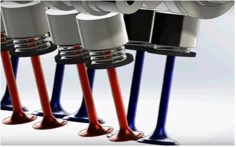
A spring is defined as an elastic machine element, which deflects under the action of load and returns to its original shape when load is removed. Coil springs (helical spring), stores energy and releases it. It functions as a shock absorber. Springs are sometimes used to maintain contacting force between the surfaces. The helical springs are made up of a wire (usually of square cross section) coiled in the form of a helix and are intended for compressive or tensile loads. In helical spring, the helix angle is very small, it is usually less than 10 degrees. The major stresses produced in helical springs are torsional shear stresses due to twisting. The load may be applied parallel to or along the axis of the spring. IC engine valve springs enable both the intake and exhaust valves to alternately open and close when the engine is in operation to permit intake and exhaust of air/fuel mixture or air. Rotation of the camshaft causes a valve to open and its spring to be compressed, so that the load on the spring is increased. The stored energy in the spring then forces the valve to close as the camshaft continues its rotation. This process occurs for each valve for each engine cycle, and over the lifetime of the engine, it occurs many millions of times. Automotive springs have to face very high working stresses.
[image:1.595.313.556.244.395.2]The structural reliability of the spring must therefore be ensured.
[image:1.595.329.551.437.649.2]Fig - 1: Valves of IC engine
Fig - 2: Cutaway Drawing of a section of IC engine showing Valves and Valve springs
2. PROBLEM STATEMENT
© 2017, IRJET | Impact Factor value: 5.181 | ISO 9001:2008 Certified Journal
| Page 52
parameter values that will give the lowest mass for the samelift within the specified stress limits
3. LITERATURE REVIEW
In 1678, Robert Hooke in his work “De Potentia Restitutiva” published. This simple statement, today known as Hooke’s law yields the basic equation for spring design.
In 1770, Lagrange analyzed the proportion of loads and deflection in springs.
In 1813, A. Roever proposed a theory describing the maximum bending and shear stresses on spring coils.
In 1902, French published formulas for calculating torsional elasticity and safe stress levels for different ratios of wire to coil diameters.
In 1929, Arthur Wahl proposed a stress correction factor to take into account those additional stresses using torsion theory and carried out tests that were in good agreement with the values theoretically predicted.
In 1947, Finniecome compared Roever’s and Wahl’s correction factors and determined that for springs with spring index above 3 Wahl’s values were slightly higher than Roever’s.
Wahl (1939, 1949, 1963) analyzed the use of the curvature correction factor in springs with large deflections, with free and fixed ends, under fatigue loading and endurance.
An excellent analysis of when and when not to use the stress correction factor was presented by Carlson in 1985.
4. DESIGN OF VALVE SPRING
Spring material
Chrome Vanadium Steel:
ASTM 232 chrome–vanadium steel is used. Spring wire is normally cold drawn to the desired diameter; so that the tensile strength increases with the amount of drawing. These materials are designed for springs that must withstand considerable shock, extreme heat and resistant to fatigue. Valve spring quality chrome vanadium has been eddy current tested to assure the finest possible surface in keeping with automotive industry requirements. The following table shows the composition of Chrome Vanadium Steel:
Table-1: Composition of Chrome Vanadium
COMPONENT %
Carbon (C) 0.48 - 0.53 Manganese (Mn) 0.7 – 0.9 Phosphorus (P) <0.04
Sulphur (S) <0.04 Silicon (Si) 0.15- 0.35 Chromium (Cr) 0.8-1.1 Other (Ni, V etc) < 0.15
Young’s Modulus = 207000 MPa Modulus of Rigidity = 87500 MPa Density = 7800 kg /m3
Poisons ratio = 0.28
Tensile Strength (Sut) = 169,000(d)^(-0.167) = 1618.08 MPa Shear strength of material = 809.04 MPa
Other Specifications
1. Outer diameter of the coil (Do) = 22.542 mm 2. Inner diameter of the coil (Di) = 15.431 mm 3. Wire diameter (d) = 3.556 mm
4. Pitch (P) = 5.22 mm
5. Mean diameter of coil (D) = 18.9865 mm 6. Total number of coils (N) = 6
7. Number of active coils (Nt) = 4 8. Mass of the spring = 0.0326 kg 8. Free length (Lo) = 31.336 mm 9. Solid length (Ls) = 21.336 mm 10. Maximum Force (F) = 225 N 11. Spring Index (C) = 5.3392 12. Wahl’s stress factor (Ks) =
= 1.288
13. Shear Stress (𝛕)
= 311.5 N/mm2 14. For cyclic loading Sut = 1618.08 N/mm2
Endurance Limit of the component subjected to fluctuating torsional shear stress (Sse) = 404.52MPa
Design stress (𝛕d) = Sse /Fs = 404.52/1.2 = 337 N/mm^2
Hence, the design is safe as 𝛕d > 𝛕
5. MODELING AND STATIC ANALYSIS OF VALVE
SPRING
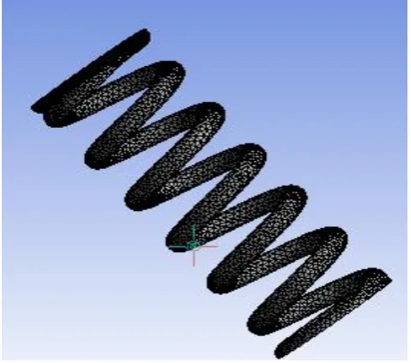
5.1 CAD Model
© 2017, IRJET | Impact Factor value: 5.181 | ISO 9001:2008 Certified Journal
| Page 53
Fig - 3 CAD Model of valve spring5.2 Meshing
The mesh was generated using proximity and curvature as an option. For the valve spring, the mesh was created as Triangular surface mesher. The minimum edge length was taken as 5.5858e-003 m and for checking the solutions the mesh was made finer and the solutions were obtained.
Fig – 4 Meshing of the CAD Model
5.3 Boundary Conditions and FEA
[image:3.595.49.557.54.254.2]A force of 225N is applied in the Y direction and the boundary condition is applied at the end of the valve spring. Static analysis is carried out by using ANSYS WORKBENCH 14.5. The results for shear stress, total deformation are shown.
Fig – 5 Shear stress analysis of valve spring
Maximum shear stress for valve spring is 307 MPa.
[image:3.595.308.557.333.494.2]We observe maximum shear stress occurs at the curvature of the spring.
Fig – 6 Total deformation of valve spring
Maximum deformation for valve spring is 6 mm
[image:3.595.47.277.388.591.2]Comparison of the results by Conventional Calculations and by Finite Element Analysis
Table-2: validation of results
We observe the shear stress is much below the shear strength of material which is 809.04 MPa. The shear stress is also much below the endurance limit of the material which is 404.52 MPa which makes it resistant to fatigue.
© 2017, IRJET | Impact Factor value: 5.181 | ISO 9001:2008 Certified Journal
| Page 54
6. MASS OPTIMIZATION OF THE VALVE SPRING
6.1 Methodology
The objective is to reduce the mass of the valve spring within the defined stress limits and deformation. Spring Index (C) is defined as the ratio of mean coil diameter (D) to the wire diameter(d). Input parameters wire diameter (d) and the mean coil diameter (D) is varied to achieve reduction in weight and hence material costs. The goal is to find the exact combination of parameter values that will give the lowest mass within the specified stress limits.
While the initial designing, the original mass of the coil spring was 32.674 g
Response surface study in ANSYS WORKBENCH 14.5 is done for optimization of mass of the spring. A Central Composite Design DOE type and Auto Defined Design Type is selected, which optimizes the weight of the coil spring based on number of input parameters.
Input Parameters
1. Radius of spring coil Lower bound = 9 mm Upper bound = 10 mm Value = 9.4933 mm
2. Wire diameter Lower bound = 3 mm Upper bound = 4 mm Value = 3.556 mm
ANSYS WORKBENCH response surface study gives the following output results.
Output Values
Response Surface Study in ANSYS WORKBENCH gives different values for Mass, Deformation and Shear stress according to the different combination of input parameters.
Table-3: Variation of output parameters w.r.t input parameters
The graph shows the variation of output values (solid mass and deformation) in accordance with input values
Chart - 1: Design point v/s parameter chart
In the design point v/s parameter chart we observe that design point 6 has minimum solid mass and has a deformation of 0.0104 m. Hence, this does not give us optimum results.
Chart – 2: Response surface chart
© 2017, IRJET | Impact Factor value: 5.181 | ISO 9001:2008 Certified Journal
| Page 55
6.2 Results
After the response surface study, a response surface optimization was obtained. Ansys Workbench 14.5 predicts the optimum combination of parameters to achieve this. Candidate points, where minimum mass of the spring is obtained within the specified stress limits and deformation are shown below:
Table-4: Results
Chart -3: Output values obtained at different candidate points
Hence, we observe there is a reduction of 5.74 % of mass of the automotive spring at candidate point 1 where coil radius is 9.0465 mm and wire diameter is 3.453625 mm. At candidate point 2, a reduction of 2.52 % of mass is obtained with coil radius 9.19 mm and wire diameter 3.488mm. We also observe the deformation and shear stress is well within limits at all the points predicted.
Hence, weight of the valve spring is optimized within the specified limits and input parameters.
7. CONCLUSIONS
The automotive valve spring is modeled, analyzed and its weight optimized in the present work. The automotive valve spring should be shock resistant, fatigue resistant and should be able to bear extreme heat. Theoretical and FEA analysis
on ANSYS WORKBENCH 14.5 was carried out on the automotive valve spring to ensure the structural reliability. A response surface study was carried on ANSYS WORKBENCH 14.5 to optimize the weight of the valve spring. A reduction of 5.74% in weight of the valve spring is achieved by varying the Spring Index. The stress limits and deformation are well within range. Reduction in weight of valve spring would reduce material costs and increase efficiency of the engine. Hence, a better design of the valve spring was obtained.
REFERENCES
[1] Design of Machine Elements, 3rd Edition, V.B. Bhandari, McGraw Hill Publications.
[2] Wahl AW, “Mechanical springs” in McGrawHill Book Company,Inc.; 1963.
[3] Shigley J. Mechanical engineering design. New York: McGraw-Hill; 1981.
[4] Mehdi Bakhshesh and Majid Bakhshesh [5], in their research, had studied steel helical spring under uniform loading. They compared the Finite Element Analysis results with analytical solutions.
[5] Aurel P. STOICESCU, “On The Optimal Design of Helical Springs of An Automobile Suspension”, U.P.B. Sci. Bull., Series D, Vol. 71, Iss. 1, 2009, pp. 81-94.