© 2017, IRJET | Impact Factor value: 5.181 | ISO 9001:2008 Certified Journal
| Page 446
Compelete analysis of chasis design of automobile vehicle using finite
element method
1
Vidyadhar biswal,
2Rohit goyal,
3Mandeep chhabra,
4Varun shukla,
5Abhishek vig,
1
Vidyadhar Biswal, Assistant professor, Chandigarh University, Gharuan,Punjab,India.
2Rohit goyal, Assistant professor
, Chandigarh University, Gharuan,Punjab, India.
3
Mandeep chhabra,
UG
student, Chandigarh University, Gharuan,Punjab,India.
4Varun shukla,
UG student, Chandigarh University, Gharuan.
,
Punjab,India.
5
Abhishek vig, UG
student, Chandigarh University, Gharuan,Punjab, India.
---***---Abstract - Finite element stress analysis of chassis plays
an important role during design stages. The paper focused on stress analysis of the chassis using finite element package ANSYS. The current work contains the load cases & boundary conditions for the stress analysis, deformation analysis of chassis.
Key Words:
stress analysis, deformation analysis of chassis,chasis design.
Introduction
-Chassis is a French term and was at first used to denote the frame components or Basic Structure of the vehicle. It’s the rear bone of the vehicle. A vehicle without body is termed Chassis. The elements of the vehicle like powerhouse, gear, Axles, Wheels and Tyres, Suspension, dominant Systems like Braking, Steering etc., and conjointly electrical system components mounted on the Supra Chassis frame. It combines all the elements together with the body. Therefore it's conjointly known as Carrying Unit.CHASSIS
• Cockpit Opening &Cockpit Internal Cross Section must be as per the template
• Any portion of frame which might be in contact with driver helmet must be padded.
• . Firewall &Floor Close-out must be of suitable material as per the rules.
• Restraints, its attachments and mounting must be strong enough to withstand a force of 890N.
SUSPENSION & WHEELS
• The suspension system with shock absorbers must have minimum travel of 2 inches.
• The smaller track of the vehicle must be no less than 75% of the larger track.
• The wheels of the car must be 8.0 inches or more in diameter.
• The car must have a wheelbase of at least 1525 mm (60 inches).
BRAKING & SAFETY
• Brake pedal must be designed to withstand a force of 2000N.
• The braking system must act on all four wheels and be operated by a single control.
• The vehicle must be equipped with two (2) master switches which form part of the shutdown system.
STEERING
• Allowable free play for the steering system is limited to 7 degree measured at steering wheel. • The steering wheel must be mechanically
connected to the wheels.
ENGINE
• Limitation of Engine displacement is set to below 610cc.
• The throttle must be actuated mechanically, i.e. via a cable or a rod system.
• Intake System Restrictor of 20mm must be used. • The maximum permitted sound level from the
[image:1.595.318.567.550.743.2]vehicle is 110 dBA.
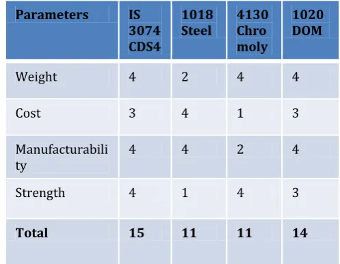
Table -1:
Parameters IS 3074 CDS4
1018
Steel 4130 Chro moly
1020 DOM
Weight 4 2 4 4
Cost 3 4 1 3
Manufacturabili
ty 4 4 2 4
Strength 4 1 4 3
© 2017, IRJET | Impact Factor value: 5.181 | ISO 9001:2008 Certified Journal
| Page 447
• All the suspension, steering and engine mountingpoints are nodded.
• Inside out approach for cockpit design.
• All the analysis are done by taking engine as a structural member.
[image:2.595.46.583.93.806.2]• Frequency Range: 12.7 - 31.875 Hz
Fig – 1:
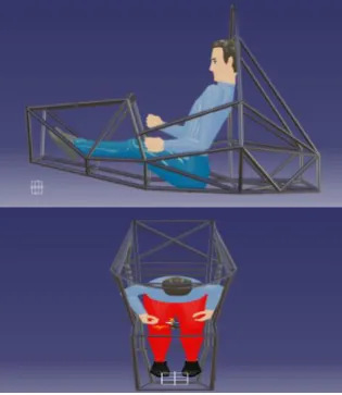
ERGONOMICS & ANTHROPOMETRYFig-2:
SUSPENSIONTable -2:
Fig – 3: ELECTRONICS
BATTERY 12V
BRAKE LIGHT 10W
DASHBOARD DISPLAY
10W
2 KILL SWITCH
1 BRAKE OVERTRAVEL SWITCH
Fig – 4: INTAKE AND EXHAUST
Intake system
Runner diameter = 38 mm
Design Considerations
• Spring Stiffness
18N/mm(F)
27.5N/mm(R)
• Weight Ratio
40:60
• Wheel Frequency
3Hz
• Roll Centre
15 – 30 % of C.G Height
• Damping Ratio
Less than 1
• Roll Angle
0.124
0• Motion Ratio
0.99FR 0.98RR
Dashboard height = 596mm(5,4’’)
Reclined seating position with legs elevated
Adjustable brake pedal(152.4mm)
Seat thigh angle=27deg
[image:2.595.38.196.194.376.2]© 2017, IRJET | Impact Factor value: 5.181 | ISO 9001:2008 Certified Journal
| Page 448
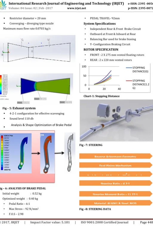
Restrictor diameter = 20 mm [image:3.595.42.556.44.819.2] Converging – diverging type nozzle Maximum mass flow rate 0.0703 kg/s
Fig – 5:
Exhaust system
4-2-1 configuration for effective scavenging Sound level 110 db
Fig – 6: ANALYSIS OF BRAKE PEDAL Initial weight : 0.52 kg Optimized weight : 0.40 kg
• Pedal Ratio – 6:1 • Max Stress – 92 N/mm2
• F.O.S – 2.98
• PEDAL TRAVEL- 92mm
System Specifications
• Independent Rear & Front Brake Circuit • Outboard at Front & Inboard at Rear • Balancing Bar used for brake biasing • Y- Configuration Braking Circuit
ROTOR SPECIFICATION
• FRONT : 2 X 275 mm vented floating rotors • REAR : 2 x 220 mm vented rotors
Chart-1: Stopping Distance
Fig –7: STEERING
Fig –8: STEERING DATA
0 50 100
0 20 40
STOPPING DISTANCE(G)
STOPPING DISTANCE(1.2 G)
Analysis & Shape Optimization of Brake Pedal
Steering Moment Ratio – 11.27:1
Material :Al 6061 & Steel 8620
Steering Ratio – 4.2:1
Rack Travel – 23.5mm for 90
0Steer Angle
Reverse Ackermann Geometry
© 2017, IRJET | Impact Factor value: 5.181 | ISO 9001:2008 Certified Journal
| Page 449
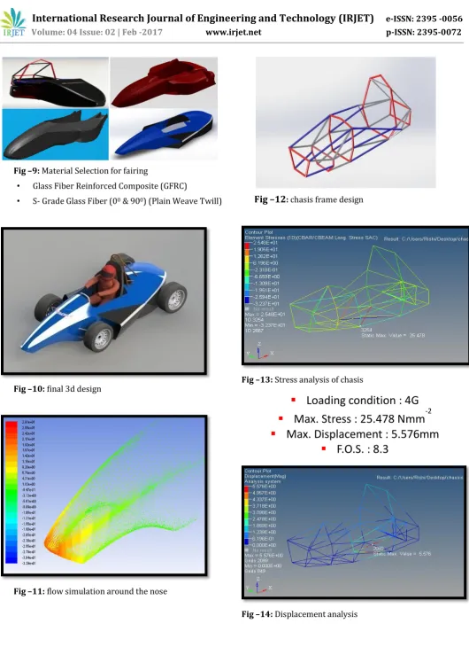
Fig –9: Material Selection for fairing• Glass Fiber Reinforced Composite (GFRC)
[image:4.595.35.566.35.766.2]• S- Grade Glass Fiber (00 & 900) (Plain Weave Twill)
Fig –10: final 3d design
Fig –11: flow simulation around the nose
[image:4.595.34.272.290.458.2]Fig –12
: chasis frame designFig –13: Stress analysis of chasis
Fig –14: Displacement analysis
Loading condition : 4G
Max. Stress : 25.478 Nmm
-2
Max. Displacement : 5.576mm
© 2017, IRJET | Impact Factor value: 5.181 | ISO 9001:2008 Certified Journal
| Page 450
[image:5.595.305.559.96.310.2]Fig –15:
Front upright model
Fig –16:
Front upright Material Used – Al 6061 (T-6) Stress Induced – 121 N/mm2
[image:5.595.40.464.293.797.2] Max. Deflection – 0.9 mm F.O.S – 2.4
Fig –17:
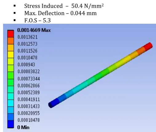
Wheel Hub Material Used – Al 6061 (T-6)
Stress Induced – 50.4 N/mm2
Max. Deflection – 0.044 mm F.O.S – 5.3
Fig –18:
Rear Axle Material Used – AISI 4130 Stress Induced – 286 N/mm2
Max. Deflection – 1.4 mm F.O.S – 2.5
3. CONCLUSIONS
It is necessary to use the finite element model of the structure for analysis of the vehicle chassis. Here lot of work has been done before finalizing the boundary conditions & load cases are calculated, then checked. The finite component model has been tested to the experimental results. The same finite component model has been used for the fatigue analysis of the chassis.In this paper an attempt is made to analysis of SAE supra chassis frame.