© 2017, IRJET | Impact Factor value: 6.171 | ISO 9001:2008 Certified Journal
| Page 1946
Wire Stranding Machine Failure Investigation
Maruti Kunnurkar
1, Anil Pol
2, Deepak Rotti
31
PG student, Department of Product Design and Manufacturing VTU PG Studies Belgaum, KARNATAKA, INDIA
2Asst Professor, Department of Product Design and Manufacturing VTU PG Studies Belgaum, KARNATAKA, INDIA
3
Project Leader QuEST, KARNATAKA, INDIA
---***---Abstract - The wire stranding machines are used to strand
the number of small wires into one bundle or wrap together to form a bunch of wire. These machines are used in electrical industries for stranding copper wires. Also these machines are used to strand the wire rope of composite thread material.
The stranded wires will be more flexible than the single wire as the ductility of wires increases since the each small wire gauge thickness will be less.
Basically these machines have a common issue of mechanical failure of their parts like shaft, cradle and off board support. Due to these failures the operation of the machine will be completely stopped and it will affect to the production target of the companies. Also due to several failures of these machines the product reliability & operator safety came into concern and affected to the company’s customer satisfaction index. Internally this could create problem to withstand the company’s product in the market.
Key Words: Failure investigation, fatigue life, design modifications.
1.
INTRODUCTION
The subject machine considered in the presented failure investigation is the planetary wire stranding machine which is the equipment used to strand small threads of wire into bundled one. It is also used to wrap the wire to form the bunch of wires. The stranded wires applications are majorly found in electrical industries also the stranded wires applications are found to prepare the wire ropes in composite thread material.
A wire is a single, cylindrical and flexible rod of metal. Wires are used to bear mechanical loads, electricity and telecommunications signals. Usually wires are commonly formed by drawing operation which involves drawing the metal through a hole in a die or draw plate. Wire specifications are measures in terms of gauge thickness and are exist in various standard sizes, expressed in terms of a gauge number. A multiple wires stranded to form the bundle which is more correctly termed a wire rope in mechanics, or a cable in electricity.
Wires exist in solid core, stranded, or braided forms and usually in circular cross-section. Although wire can be made in square, hexagonal, flattened rectangular, or other
cross-sections, either for decorative purposes, or for technical purposes such as high-efficiency voice coils in loudspeakers. Edge-wound coil springs, such as the Slinky toy, are made of special flattened wire.
A solid wire or single strand wire consist of one piece of metal wire and it is cheaper to manufacture but the flexibility of the wire will be less. These wires are used where there is little need of flexibility. Solid wire provides mechanical ruggedness as it has less exposure of surface area to corrosive environment compare to multistring wires.
The stranded wire is composed of number of small wires bundled or wrap together to form a single larger conductor. This wire will be more flexible than the single one because the ductility of wires increases since each small wire gauge thickness will be less compare to single one with higher thickness. Stranded wire tends to be a better conductor than solid wire as collective surface area is grater in stranded wire. These wires are used in situations where there is a requirement of higher resistance to metal fatigue.
2. PROBLEM STATEMENT
Historically these wire stranding machines have several issues with mechanical failure of its shaft, cradle or off board support structures. Any mechanical failure of parts will stop the entire operation of the machine, which will affect to the production target of the companies. Also mechanical failure of parts will put operator safety into concern. As these machines are rotatory machines mechanical failure of part will have chances of part being thrown out with high centrifugal force and when it hit to any other part or human operator, they may get seriously injured or part may get broke due high impact.
Due to several failures of these machines the product reliability & operator safety came into concern. This affected to the company’s customer satisfaction index and problem to withstand the company’s product in the market.
In current failure investigation failure of weld joint at cradle structure is investigated.
3. Planetary Wire Stranding Machine configuration.
© 2017, IRJET | Impact Factor value: 6.171 | ISO 9001:2008 Certified Journal
| Page 1947
structural component of this machine is the center shaft on [image:2.595.69.254.166.283.2]which a support plate is mounted. The cradles are mounted in between two consecutive support plate through a bolting joint. The main center shaft will be driven through motor mounted on the one end of machine and is been supported by bearing support at another
Fig - 1:View representing typical planetary wire stranding Machine
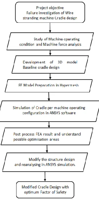
3.1 Methodology
The overall methodology followed to carry out this project is detailed per the flowchart mentioned in Figure 2
Fig - 2:Investigation Methodology
3.1.1 Study of Machine operating Condition & Force
Analysis:
The machine considered for this cradle weld design rotates at 80 rpm. Cradle rotates along with the machine at a speed of machine rotation, and is located at a radius of 25 inches from the axis of rotation of the machine.
Due to Machine rotation about its axis a centrifugal force will be acting on the cradle due to its mass.
As machine is continuously rotating a quasistatic force equilibrium condition is been analysed for carrying out the analysis. Refer Figure 3
[image:2.595.322.541.319.468.2]As per this four position of machine are analysed which are machine standing at 12 o clock position, 3 o clock position and 6 o clock position and 9 o clock position.
Fig - 3:Machine positions in Quasistatic state
3.1.2 Development of 3D Model and FE Model:
Engineering models today are mainly developed within 3D computer aided design (CAD) software, for the reasons that the CAD models are unambiguous, visualization and manufacturing-planning is easier within the environment, and 3D model data exchange is well established. The 3D models created using these CAD systems often contain an abundant amount of features.
The CAD model is created by using Solid works tool due to the ease of use and the ability to import .igs files into Hyper Mesh. Generally CAD data is provided in *.Step or *.igs format.
Before starting FEA, geometry should be carefully checked for: Free edge, Scar lines, Duplicate Surface, Intersection of parts
[image:2.595.81.255.395.754.2]© 2017, IRJET | Impact Factor value: 6.171 | ISO 9001:2008 Certified Journal
| Page 1948
The ultimate purpose of a finite element analysis is torecreate mathematically the behavior of an actual engineering system. In other words, the analysis must be an accurate mathematical model of a physical prototype. In the broadest sense, this model comprises all the nodes, elements, material properties, real constants, boundary conditions, and other features that are used to represent the physical system.
In ANSYS terminology, model generation usually takes on the narrower meaning of generating the nodes and elements that represent the spatial volume and connectivity of the actual system.
Below general steps were followed for creation of FE Model in this investigation
• Prepare the CAD model.
• Cradle structure is meshed using Hypermesh Tool . • Second order tetra elements are used to mesh the
components.
• ANSYS is used as a FEA solver tool.
[image:3.595.328.542.348.506.2]• Boundary conditions finalised based on different iterations to achieve field failure on Cradle and per machine operating conditions.
Fig - 4: Prototype of CAD Models
Fig - 5: FE Model of prototype
3.1.3 Simulation of Machine operating condition & its Results:
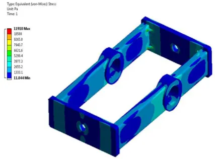
3.1.3.1 Baseline Analysis. Case I
Analyzing the factor of safety on baseline design is performed in this case where machine maximum operating condition is simulated and its effect on structure analysed by finding out the reserve factor on yield.
The result of factor of safety on yield is shown in Table 1.
SL
No Description
Induced Equivalent Stress ( ksi
Allowable Yield strength ( ksi)
Reserve factor
1 Baseline 11.9 36 3.02
Per table 1 result, it is found that Factor of safety on yield is 3.15 which proves that that design is safe
Fig - 6: FE simulation result of case I
3.1.3.2 Baseline Analysis. Case II
As further investigation of the machine actual operation and failed cradle evidences, below mentioned possible failure observations were found during investigation.
• Crack initiation and propagation
• Bobbin weight could slide towards one end and it could hit to cradle tube when it is at 3 o clock & 9 o clock positions.
To verify these findings simulations were performed as machine location changes at 3, 6, 9 & 12 O Clock position detailed in Figure 3.
For fatigue failure analysis, the British standard BS 7608:1993 [7] was used. The class of the welded joint was considered as class F for the full penetration weld. From this data the allowable stress range is taken to have life of weld
[image:3.595.54.272.388.554.2]© 2017, IRJET | Impact Factor value: 6.171 | ISO 9001:2008 Certified Journal
| Page 1949
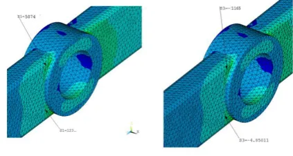
The maximum principle tensile and compressive stresseswere extracted at the same point for 3 and 9 ‘o’ clock positions and for 6 and 12 ‘o’ clock positions. The total stress range is calculated from the formula:
Stress range = Maximum principle tensile stress (S1) + Maximum principle compressive stress (S3).
The reserve factors on fatigue are given in Table 2. FE simulation results are depicted in figure 7.
SL
No Description
Induced Equivalent Stress range ( ksi) Allowable stress range for
107cyacles
( ksi)
Reserve factor
1 Baseline Reverse
Loading 19.8 7.05 0.35
[image:4.595.318.530.94.207.2]5. FATIGUE LIFE CALCULATIONS:
Fig - 7: FE simulation result of case II
3.1.3.3 Modified Model. Case III
As the existing design was failing in the fatigue consideration, design modifications were performed for cradle baseline model. After performing FEA for modified design, the modified model results in factor of safety > 1 which is good to
suatain the cradle structure for 107 life cycles as detailed
below in Table 3 and Figure 8.
SL
No Description
Induced Equivalent Stress range ( ksi Allowable stress range for
107cyacles
( ksi)
Reserve factor
1 Modified Model 6.2 7.05 1.13
Fig - 8: FE simulation result of case III
6. CONCLUSION
1. The existing cradle design (baseline model) was analyzed for the yield strength, the cradle found to be safe in yield. 2. The cradle was experiencing the reverse loading (3 & 9 ‘o clock and 6 & 12 ‘o clock positions) so it was analyzed for fatigue strength. In fatigue the baseline model of cradle stress range of 21 ksi was observed for full penetration of weld and as per the British standard BS 7608:1993 [7], the allowable stress range is 7.05 ksi for the class F full penetration of weld. The reserve factor on the fatigue life is 0.33 (<1) which is not safe and the component may experience failure before 107 cycles.
3. This proves that the cradle design is weak in fatigue life when reverse loading on cradle structure is observed due to centrifugal force and bobbin weight slide. After modification in the cradle design the induced stress range in the cradle reduced to 6.9 ksi for 3 & 9 ‘o’ clock, giving a reserve factor
of 1.05 for fatigue life of 107 cycles respectively.
4. Result comparison for baseline and modified result is in Table 4.
SL
No Description
Induced Equivalent Stress range ( ksi) Allowable stress range for
107cyacles
( ksi)
Reserve factor
1 Baseline Reverse
Loading 19.8 7.05 0.35
2 Modified Model 6.2 7.05 1.13
REFERENCES
[1] Failure analysis of V-shaped Plates under Blast Loading, 11th International Symposium on Plasticity and Impact Mechanics, Implast 2016.
[2] Kubhalkara Manoj A, Material and Stress Analysis of Railroad Vehicle Suspension: A Failure Investigation, 2nd
International Conference on Nanomaterials and
[image:4.595.32.295.597.682.2]© 2017, IRJET | Impact Factor value: 6.171 | ISO 9001:2008 Certified Journal
| Page 1950
[3] Ziegler D, Investigation of Turbine Blade Failure in aThermal Power Plant, Case Studies in Engineering Failure Analysis 1 (2013) 192–199.
[4] Rao Vinay N, Failure analysis of mixed mode crack growth in heavy duty truck frame rail Case Studies in Engineering Failure Analysis 5–6 (2016) 67–74
[5] Fontea M, Failure mode analysis of two diesel engine crankshafts, XV Portuguese Conference on Fracture, PCF 2016, 10-12 February 2016, Paço de Arcos, Portugal.
[6] Zucarelli T A, Failure analysis in railway wheels, XV Portuguese Conference on Fracture, PCF 2016, 10-12 February 2016, Paço de Arcos, Portugal.