A Study of Induced Soil-Arching Effect in Backfilled Soil for
Underground Tunnel
Dr. U.B.Choubey
1, Er. Govind Parchani
2, Mohak Patel
31
Professor, Dept. Of Civil Engineering and Applied Mechanics, SGSITS, Indore, Madhya Pradesh
2Head, Civil Design and Construction Cell, RRCAT, Indore, Madhya Pradesh
3
PG Scholar, Dept. Of Civil Engineering and Applied Mechanics, SGSITS, Indore, Madhya Pradesh
---***---Abstract- A tunnel is an underground structure which
involves a huge construction cost. If the load on tunnel roof is reduced, it will result in reduced construction cost. There is an urgent need to do research work pertaining to decrease the load on tunnel and decreasing the construction cost. Arching is the phenomenon in which transfer of forces between a yielding mass of geometrical and adjoining stationary members. A redistribution of stresses in the soil body takes place. The shearing resistance tends to keep the yielding mass in its original position resulting in a change of the pressure on both of the yielding part's support and the adjoining part of soil. Practically it is seen that in case of bored tunnel there is natural soil arching behaviour present in soil as there is minimal ground disturbance and hence there is minimal support requirements. But in case of cut and cover method of tunnelling, backfilled soil does not possess soil arching effect. High Density Polyethylene (HDPE) Geomembrane possesses a high tensile strength and other physical properties. The present investigation involves the use of HDPE to reduce the overburden pressure of backfilled soil over the roof of tunnel. This involves the investigation of effectiveness of geomembrane at different depth and for different span. From this experimental study soil arching is successfully achieved for cut and cover method of tunnelling and the geomembrane is found to be cost effective for tunnel construction.Keywords: Tunnel, Cut-And-Cover method of tunneling, Bored Tunnel, High Density Polyethylene (HDPE) Geomembrane, Soil Arching.
1. INTRODUCTION
A tunnel is an underground or underwater passageway, dug through the surrounding soil/earth/rock and enclosed except for entrance and exit, commonly at each end. Tunnels are dug in types of materials varying from soft clay to hard rock. The method of tunnel construction depends on such factors as the ground conditions, the ground water conditions, the length and diameter of the tunnel drive, the depth of the tunnel, the logistics of supporting the tunnel excavation, the final use and shape of the tunnel and appropriate risk management.
Cut-and-cover is a simple method of construction for shallow tunnels where a trench is excavated and roofed over with an overhead support system strong enough to carry the load of
what is to be built above the tunnel. Tunnel construction is categorized as “Cut-and-Cover” construction when the tunnel structure is constructed in a brace, trench type excavation (“cut”) and is subsequently backfilled (“covered”). For depths up to 35-45 ft this method is often cheaper and more practical than underground tunneling.
ARCHING is a phenomenon that occurs when a yielding part of a soil mass transfers pressure to adjoining soil mass which is less yielding or rigid. The action is similar to one in a structural arch which transfers the load to abutments. When a part of the soil mass yields, it has a tendency to move out of its original position. This tendency is resisted by the shearing resistance at the zone of contact between the yielding and non yielding parts. Consequently, the pressure on the yielding part is reduced, whereas that on the non-yielding parts is increased. The soil thus arches over the yielding part and transfers the load to the non yielding parts which act as abutments.
A Geomembrane is very low permeability synthetic membrane liner or barrier used with any geotechnical engineering related material so as to control fluid migration in a human-made project, structure, or system. Geo membranes are made from relatively thin continuous polymeric sheets. Geomembrane used in our experiments is High Density Polyethylene (HDPE) White Smooth Geomembrane.
This research work basically aims at the effectiveness of Geomembrane to reduce the overburden pressure of soil over the roof of tunnel which is a representation of soil arching for cut-and-cover method of tunneling.
1.1 Aim and Objective of Research
The main objective of this research is to induce soil arching effect in the backfilled soil for cut-and-cover tunnel with the help of geomembrane as the natural soil arching is not possible in backfill soil of cut-and-cover tunnel.
The sub objective includes the following:
2. To find the effectiveness of geomembrane in reducing the overburden pressure of backfill soil over the roof of tunnel by introducing it at different depth of backfill soil.
3. To find out the variation of effectiveness of geomembrane at different depth of backfill soil.
4. To find out the variation of effectiveness of geomembrane for different span.
1.2 PROBLEM FORMULATION
In this experimental study the effect of geomembrane on the overburden pressure of soil over the roof of tunnel has been investigated mainly. The geomembrane used in the experiments is HDPE High Density Polyethylene white smooth geomembrane of thickness 1.5 mm. Also deflection test was performed in trench of 2m X 2m excavated at site on Mild Steel plate of designed thickness of 5 mm. the width of plate was 600 mm and spans 420 mm, 600 mm and 710 mm respectively. There are basically four main steps of this study which are as follows:
1. Testing of Geomembrane. 2. Construction of trench. 3. Deflection test.
4. Calculations and analysis for effectiveness of geomembrane.
2. METHODOLOGY ADOPTED
Experiments were performed in laboratory as well as in site. Testing of geomembrane was performed in lab and deflection test was performed for different cases at site. The methodology used for experimental study is described below.
2.1 TESTING OF GEOMEMBRANE
Geomembrane used in this experimental study is HDPE High Density Polyethylene white smooth geomembrane. Testing of geomebrane is performed to find out its strength and other properties so it can be used for different site conditions. As the geomembrane is used with geotechnical materials so there are different forces which act on it. It is necessary for geomembrane to be strong enough to resist all the tensile forces, penetration of stones, etc so that the properties of geomembrane can be fully utilized. The tests performed on geomembrane to find out its properties are as follows.
1. Thickness
2.2 DEFLECTION TEST
This test was performed to find out the deflection of MS Plate due to the overburden pressure of soil. Following methodology is adapted for experimental study:
1. The experiments were performed in a trench of size 2 m x 2 m excavated on the open ground. This 2 m x 2 m space is used for observation and performance of experiment.
2. Depth of trench was 2 m. Bottom 500 mm was used for measurement of deflection and 1500 mm was used for backfilling of soil.
3. Experiments were performed over MS Plate of designed thickness 5 mm and width was 600mm.
4. The MS Plate was provided at the height of 500 mm. 5. Deflection of plate was measured for three spans of 420
mm, 600 mm and 710 mm.
6. The deflection of plate was measured for different thickness of backfill soil i.e., for 500mm, 1000mm & 1500mm.
7. The deflection of MS plate was also measured with geomembrane introduced at different level of backfilled soil for corresponding depth.
Deflection test was performed for three different cases for the different positions of geomembrane.
3. DESCRIPTION OF DIFFERENT CASES
The deflection of plate was measured for overburden pressure of backfilled soil with and without geomembrane. Hence there are three cases for which deflection was measured for different span. The three cases are discussed below.
1. Backfilled soil without Membrane.
2. Backfilled soil with Membrane at height 500 mm from plate.
3. Backfilled soil with Membrane at height 500 mm & 1000 mm from plate.
Case I: Backfilled soil without membrane
In this case deflection of MS Plate was measured for 3 layers of soil (each of 500 mm) without any geomembrane at intermediate level for all three spans of 420 mm, 600 mm and 710 mm.
Case II: Backfilled soil with membrane at height 500 mm from plate
Case III: Backfilled soil with membrane at height 500 mm & 1000 mm from plate
In this case deflection of MS Plate was measured for 3 layers of soil (each of 500 mm) with geomembrane introduced at height of 500 mm and 1000 mm from plate for all three spans of 420 mm, 600 mm and 710 mm.
4. RESULTS & DISCUSSION
Experiments were performed for different cases of deflection test to find the deflection of MS Plate due to overburden pressure of backfilled soil. Also the effectiveness of geomembrane i.e., percentage reduction in deflection, percentage reduction in overburden pressure, upward pressure due to geomembrane and tensile force acting on geomembrane was calculated mathematically. From the above experiments and calculations, the results are found for following headings
1. Test results of Geomembrane.
2. Deflection of MS Plate for different span. 3. Percentage reduction in deflection. 4. Upward pressure due to Geomembrane.
5. Percentage reduction in overburden pressure due to Geomembrane.
6. Tension in Geomembrane.
4.1 Test Results of Geomembrane
From the different lab tests performed on HDPE geomembrane following results are found. The results are shown in table-1.
Table-1: Test results of geomembrane
S.
No. Properties Tested Method Test Minimum Average Value
1. Thickness, mm ASTM D
5199 1.5
2. Density, 𝑔𝑚 𝑐𝑚3 ASTM D
1505 0.940
3. (A)
(B)
Tensile Properties Strength At Break, N/mm
Strength At Yield, N/mm
ASTM D
6693 40 22
4. Puncture
Resistance, N ASTM D 4833 480
5. Tear Resistance, N ASTM D
1004 480
4.2
Comparison of Deflections for Different Span
1. For 710 mm Span
Comparative result of deflection test for 710 mm span for different thickness of backfill and for different cases is shown in Table-2 also results are graphically shown in fig- 1.
Table-2: Deflection for 3 cases of span 710 mm
Fig- 1: Graph of comparison of deflections for
three cases of 710 mm span
2. For 600 mm Span
Comparative result of deflection test for 600 mm span for different thickness of backfill and for different cases is shown in Table-3 also results are graphically shown in fig- 2.
Total Deflection 43 36 31
1. 0 0 0 0
2. 500 22 22 22
3. 1000 33 28 28
4. 1500 43 36 31
Membrane at 500mm &
1000mm membrane
Membrane at 500 mm Deflection (mm) Without
Table-3: Deflection for 3 cases of span 600 mm
S.No. Backfill Depth (mm)
Deflection (mm)
Without
membrane Membrane at 500 mm Membrane at 500mm & 1000mm
1. 0 0 0 0
2. 500 19 18 18
3. 1000 29 22 22
4. 1500 37 27 24
Total Deflection 37 27 24
Fig- 2: Graph of comparison of deflections for three cases of 600 mm span
3. For 420 mm Span
Comparative result of deflection test for 420 mm span for different thickness of backfill and for different cases is shown in Table-4 also results are graphically shown in fig- 3.
Table-4: Deflection for 3 cases of span 420 mm
S.No. Backfill Depth (mm)
Deflection (mm)
Without
membrane Membrane at 500 mm Membrane at 500mm & 1000mm
1. 0 0 0 0
2. 500 2 2 2
3. 1000 5 3 3
Fig- 3: Graph of comparison of deflections for three cases of 420 mm span
4.3 Percentage Reduction in Deflection
From experimental study, it is found that there is reduction in deflection due to introduction of geomembrane at different level. Percentage reduction in deflection due to geomembrane is calculated.
1. For 710 mm Span
Percentage reduction in deflection for span 710 mm is shown in Table-5 and graph representing percentage reduction in deflection is shown in Fig-4
Table-5: Percentage reduction in deflection for 710 mm span
Membrane at Height from Plate
Percentage Reduction
500 mm 16.28%
1000 mm 11.62%
. For 600 mm Span
Percentage reduction in deflection for span 600 mm is shown in Table-6 and graph representing percentage reduction in deflection is shown in Fig-5.
Table-6: Percentage reduction in deflection for 600 mm span
Membrane at Height
from Plate Percentage Reduction
500 mm 27.02%
1000 mm 8.11%
500 & 1000 mm 35.13%
Fig- 5: Graph for % Reduction in Deflection for 600 mm Span
3. For 420 mm Span
Percentage reduction in deflection for span 420 mm is shown in Table-7 and graph representing percentage reduction in deflection is shown in Fig-6.
Table-7: Percentage reduction in deflection for 420 mm span
Membrane at Height
from Plate Percentage Reduction
500 mm 33.33%
1000 mm 16.67%
500 & 1000 mm 50.00%
Fig- 6: Graph for % Reduction in Deflection for 420 mm Span
4.4 Upward Pressure Due to Geomembrane
There is downward pressure acting on plate due backfilled soil mass. When geomembrane is introduced at intermediate level, the geomembrane develop pressure on backfilled soil in upward direction. The loading action of soil and geomembrane is discussed in previous chapter. Upward pressure due to geomembrane is shown for different span.
1. For 710 mm Span
Upward pressure due to membrane for 710 mm span is shown in Table-8.
Table-8: Upward Pressure Due to Geomembrane for span 710 mm
Membrane at Height
(mm) Upward Pressure, N/mm
500 mm 2.6
1000 mm 1.89
500 & 1000 mm 4.49
2. For 600 mm Span
Upward pressure due to membrane for 600 mm span is shown in Table-9.
Table-9: Upward Pressure Due to Geomembrane for span 600 mm
Membrane at Height
(mm) Upward Pressure, N/mm
500 mm 7.4
1000 mm 2.23
3. For 420 mm Span
Upward pressure due to membrane for 710 mm span is shown in Table-10.
Table-10: Upward Pressure Due to Geomembrane for span 420 mm
Membrane at Height
(mm) Upward Pressure, N/mm
500 mm 6.17
1000 mm 3.09
500 & 1000 mm 9.26
4.5 Percentage Reduction in Overburden Pressure
Due to introduction of membrane in backfilled soil there is upward pressure acting on it. This upward pressure causes the reduction in overburden pressure. Percentage reduction in overburden pressure is calculated and results are shown below for different spans.
1. For 710 mm Span
Percentage reduction in overburden pressure for 710 mm span is shown in Table-11 and graph representing reduction in overburden pressure is shown in Fig-7.
Table-11: Percentage reduction in Overburden pressure for 710 mm span
Membrane at Height
from Plate Percentage Reduction
500 mm 16.04%
1000 mm 11.67%
500 & 1000 mm 27.71%
2. For 600 mm Span
Percentage reduction in overburden pressure for 600 mm span is shown in Table-12 and graph representing reduction in overburden pressure is shown in Fig-8.
Table-12: Percentage reduction in Overburden pressure for 600 mm span
Fig- 8: Graph for % Reduction in overburden pressure for 600 mm Span
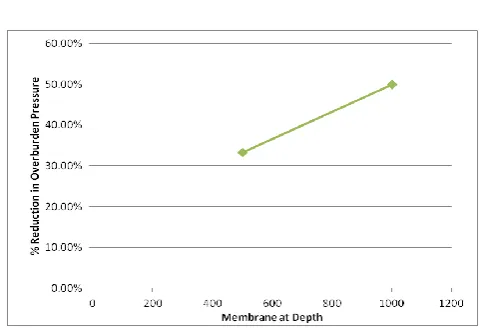
3. For 420 mm Span
Percentage reduction in overburden pressure for 420 mm span is shown in Table-13 and graph representing reduction in overburden pressure is shown in Fig-9.
Table-13: Percentage reduction in Overburden pressure for 420 mm span
500 mm 33.33%
1000 mm 16.69%
500 & 1000 mm 50.02%
Percentage Reduction Membrane at Height
from Plate
500 & 1000 mm 35.40%
500 mm 27.00%
1000 mm 8.40%
Percentage Reduction Membrane at Height
Fig- 9: Graph for % Reduction in overburden pressure for 420 mm Span
4.6 Tensile Force in Geomembrane
Due to overburden pressure of backfill soil there is tensile force acting on geomembrane. Its action is represented in loading action of geomembrane. The tensile force acting on geomembrane is calculated
1. For 710 mm Span
Tensile force acting on geomembrane at 500 mm and 1000 mm height from pate is shown in Table-14.
Table 14: Tensile Force on Geomembrane for 710 mm Span
Membrane at Height
from Plate Tensile Force
500 mm 5.85 kN
1000 mm 5.95 kN
2. For 600 mm Span
Tensile force acting on geomembrane at 500 mm and 1000 mm height from pate is shown in Table-15.
Table 15: Tensile Force on Geomembrane for 600 mm Span
Membrane at Height
from Plate Tensile Force
500 mm 8.325 kN
1000 mm 8.360 kN
3. For 420 mm Span
[image:7.595.40.283.84.248.2]Tensile force acting on geomembrane at 500 mm and 1000 mm height from pate is shown in Table-16.
Table 16: Tensile Force on Geomembrane for 420 mm Span
Membrane at Height
from Plate Tensile Force
500 mm 26.06 kN
1000 mm 26.11 kN
5. CONCLUSIONS
After obtaining the results of experiments over MS Plate for backfill soil with and without geomembrane, following conclusions are drawn.
1. It was found that geomembrane is effective for reducing
overburden pressure on roof slab of the tunnel.
2. Geomembrane is found to be more effective for shorter
span than longer span. i.e, there is approximately 50% of reduction in overburden pressure for 420 mm span whereas 27.71% for 710 mm span.
3. It is also found that membrane at larger depth is more
effective than member at lesser depth i.e., membrane at 500mm from bottom worked more effectively than membrane at 1000 mm from bottom.
4. It is concluded that there is considerable reduction in
deflection and overburden pressure; hence construction of roof slab will become economical because cost of geomembrane is less than RCC work.
5. It is concluded from results that there is considerable
reduction in deflection hence it is concluded that with the use of geomembrane, soil arching is successfully achieved for cut and cover method of tunneling.
6. FUTURE SCOPE OF STUDY
1. The experiment can be performed using different types
of geotextiles and results can be compared.
2. The experiment can be performed for different types of
soil using geomembrane or geotextiles.
3. The experiments can also be performed for reducing
lateral earth pressure on side walls using geomembrane or geotextiles.
7. REFERENCES
[1] Arora, K. R. (2011). Soil Mechanics and Foundation
[2] Bickel, J. O. and King, E. H. (2004). Tunnel Engineering
Handbook, CBS Publishers & Distributors Pvt. Ltd., New Delhi, India. Edition 2.
[3] G.S. Pardo, E. Sáez Experimental and numerical study of
arching soil effect in coarse sand Computers and Geotechnics 57 (2014) 75–84.
[4] Peter J. Bosscher and Donald H. Gray, ASCE Soil arching
in sandy slopes 112(6): 626-645.
[5] Punmia, B. C. and Jain, A. K. (2005). Soil Mechanics and
Foundations, Laxmi Publications (P) Ltd., New Delhi, India, Edition 16.
[6] Richard L. Handy,1 M. ASCE the arch in soil arching ,
111(3): 302-318.
[7] Rui, R., van Tol, A. F., Xia, Y. Y., van Eekelen, S. J., and Hu,