ii
ON THE DEVELOPMENT COMPUTER CODE FOR DETERMINIG THE ROOT OF EQUATION FOR TRANSIENT FLIGHT ANALYSIS
MUWFIK FAIDI KHAIRE ELAROSI
A project report submitted in partial fulfillment of the requirement for the award of the Degree of Master of Mechanical Engineering
Faculty of Mechanical and Manufacturing Engineering University Tun Hussein Onn Malaysia
ABSTRACT
vii
ABSTRAK
CONTENTS
TITLE ii
DECLARATION iii
DEDICATION iv
ACKNOWLEDGEMENT v
ABSTRACT vi
ABSTRAK vii
CONTENTS viii
LIST OF TABLES xi
LIST OF FIGURES xii
LIST OF SYMBOLS AND ABBREVIATIONS xv
LIST OF APPENDICES xvii
CHAPTER 1 INTRODUCTION 1
1.1 Introduction 1
1.2 Back ground 2
1.3 Problem statements 3
1.4 Thesis objective 4
1.5 Scope of study 4
CHAPTER 2 LITERATURE REVIEW 5
2.1 Type of Aircraft 5
2.2 Mission profile and overview 6
2.3 Some Examples of UAV Model Already Developed 8
2.4 Predator 9
2.4.1 Predator Description 9
2.4.2 Geometry Characteristics 9
2.4.3 Propulsion 10
ix
2.4.5 Subsystem 12
2.4.6 2.4.7
Structures Wing Control Performance
12 13
2.4.8 Predator’s Design Technology 14
2.5 Global Hawk. 15
2.5.1 Global Hawk Description 15
2.5.2 Geometry Characteristics 16
2.5.3 Propulsion 17
2.5.4 Avionics 18
2.5.5 Subsystems 19
2.5.6 Structures 19
2.5.7 Payloads 20
2.5.8 Performance 21
2.5.9 Design Technology 23
2.6 Shadow 200 23
2.6.1 Shadow 200 Description 23
2.6.2 Geometry Characteristics 24
2.6.3 Propulsion 25
2.6.4 Avionics 25
2.6.5 Subsystems 26
2.6.6 Structures 26
2.6.7 Payloads 27
2.6.8 Performance 27
2.6.9 Design Technology 29
CHAPTER 3 GOVERNING EQUATION OF FLIGHT MOTION 30
3.1 Introduction 30
3.2 General Equation of Flight Motion 30
3.3 Simplification of the Aircraft Motion 33
3.4 Longitudinal Motion Equations 33
3.4.1 Lateral-Directional Motion Equations 34
CHAPTER 4 RESULTE AND DISCUSSION 35
`4.1.2 Rate of change of Angular Velocity 37 4.1.3 Rate of change of Angular Position 38 4.1.4 Rate of change of Translational Position 38
4.2 Solution at Trim Condition 39
4.3 Computer Program Description 41
4.4 The Algorithm of Computer Code in Solving Root
Locus Problem 44
4.5 Aircraft Input Data use in The Root Locus analysis 44
4.5.1 Aircraft Geometry data 45
4.5.2 Aircraft Aerodynamic Characteristics 45 4.6 The definition of the Fortran variable which
appear in above table are given as below 49 4.7 The aerodynamic characteristic at trim condition 49 4.8 Root Locus of the present aircraft model 52
CHAPTER 5 CONCLUSION AND RECOMMENDATION 63
5.1 Conclusion 63
5.2 Recommendation 64
REFERENCES 65
xi
LIST OF TABLES
2.1 Predator geometry 10
2.2 Predator propulsion characteristics 11
2.3 Predator design technology level 15
2.4 Global Hawk geometry 16
2.5 Global Hawk propulsion 17
2.6 Global Hawk– selected performances 22
2.7 Global Hawk design technology levels 23
2.8 Shadow 200 geometry characteristics 24
2.9 Shadow 200 propulsion characteristics 25
2.10 Shadow 200 – selected performances 29
2.11 Shadow 200 design technology levels 29
4.1 Primary aerodynamics characteristic of the UAV 45
4.2 Aerodynamic derivative data of UAV-(a) 46
4.3 Aerodynamic derivative data of UAV-(b) 46
4.4 Aerodynamic derivative data of UAV-(c) 47
4.5 Aerodynamic derivative data of UAV-(d) 47
LIST OF FIGURES
2.1 Predator UAV 9
2.2 Predator Avionics Weights Summary 11
2.3 Predator Subsystems Weights Summary 12
2.4 Predator Structural Weight Summary 13
2.5 Predator Altitude Profile 14
2.6 Predator Velocity Profile 14
2.7 Global Hawk UAV 16
2.8 Global Hawk Avionics Weights Summary 18
2.9 Global Hawk Subsystems Weights Summary 19
2.10 Global Hawk Structural Weight Summary 20
2.11 Global Hawk Altitude Profile 21
2.12 Global Hawk Mach Profile 22
2.13 Shadow 200 UAV 24
2.14 Shadow 200 Subsystems Weights Summary 26
2.15 Shadow 200 Structural Weight Summary 27
2.16 Shadow 200 Altitude Profile 28
2.17 Shadow 200 Velocity Profile 28
4.1 The root locus of the transfer function of the angle of
attack α 53
4.2 The root locus of the transfer function of the horizontal
velocity u 54
4.3 The root locus of the transfer function of the pitch angle
θ 55
4.4a The zero’s variation of angle of attack α for Flight speed
85 m/sec 58
4.4b The zero’s variation of velocity in x- direction for Flight speed 85 m/s
xiii 4.4c The zero’s variation of pitch angle θ for Flight speed 85
m/sec
59
5.1a The zero’s variation of angle of attack α for Flight speed
120 m/sec 60
5.1b The zero’s variation of velocity in x- direction for Flight
speed 120 60
5.1c The zero’s variation of pitch angle θ for Flight speed 120
m/sec 61
6.1a The zero’s variation of angle of attack α for Flight speed
155 m/sec 61
6.1b The zero’s variation of velocity in x- direction for Flight
speed 155 62
6.1c The zero’s variation of pitch angle θ for Flight speed
LIST OF SYMBOLS AND ABBREVIATIONS
AG - Acceleration of gravity
ALPH - Angle of attack,
Amass - Vehicle mass, m
AT - Thrust direction cosines relative to X BT - Thrust direction cosines relative to Y Bw - Wing span, or reference length CD - Drag coefficient
CL - Lift coefficient
CLB - Coefficient of rolling moment due to beta
CLP - Coefficient of rolling moment due to roll rate
CLR - Coefficient of rolling moment due to yaw rate CM - Pitch moment coefficient
CMA - Coefficient of pitching moment due t o angle of attack
CMAD - Coefficient of pitching moment due t o
angle-of-attack rate
Cmac - Wing mean aerodynamic chord
CMQ - Coefficient of pitching moment due t o pitch rate CMO - Zero lift Pitching moment coefficient
CNP - Coefficient of yawing moment due to sideslip
CNDR - Coefficient of yawing moment due to rudder
deflection
CNP - Coefficient of yawing moment due to roll rate CNR - Coefficient of yawing moment due to yaw rate CYP - Coefficient of side force due to sideslip
Cn - Yaw coefficient
CT - Thrust direction cosines relative to Z Cy - Side force coefficient
xv P - Angular velocity about X
p - Roll rate
Q - Angular velocity about Y - Pitching acceleration
q - Pitch rate
- Dynamic pressure
R - Angular velocity about Z r - Yaw rate
SW - Wing or reference area THR - Thrust
- Longitudinal acceleration U - Velocity along X-body axis V - Velocity along Y-body axis W - Velocity along Z-body axis - Vertical acceleration
WP - Elevator servo natural frequency WR - Aileron servo natural frequency WY - Rudder servo natural frequency XE - Distance relative to inertial X axes YE - Distance relative to inertial Y axes ZE - Distance relative to inertial Z axes
Θ0 - Steady-state pitch attitude Φ - Roll angle
Θ - Pitch angle
Ψ - Yaw angle
- Angle of attack β - Sideslip angle
- Derivative of sideslip angle CFD - Computational Fluid Dynamic
NASA - National Aeronautics and Space Administration UAV - Unmanned Aerial Vehicle
LIST OF APPENDICES
APPENDIX TITLE
A B
INPUT DATA OUTPUT DATA
CHAPTRE 1
INTRODUCTION
1.1 Introduction
The governing equation of flight motions which can be used to describe the flight behavior of any type flying vehicles consist of 12 equations described 12 state – space variables involving the aircraft position and aircraft aptitude with respect to the inertial coordinate system and also with respect to their axis body system had been used. These twelve equations are coupling each to others and in the forms highly non linear equation; the numerical approach is required for solving such system equation. The coefficient of system equation can be said as a result of the combination between aircraft’s mass and inertia, aircraft geometry properties and also their aircraft aerodynamics derivatives. Such combination had made each equation which described the behavior of flight has own characteristics.
2
Through determining the root of equation one will able to carry out a non linear transient analysis such as aircraft at landing approaches gust response and pilot initiated maneuvers.
1.2 Background
The flight equation of motion represents the governing equation of flying vehicle which can be used to describe what kind movement of the flying vehicle will be. If one able to control the aerodynamic forces and moments acting on the flying vehicle at any instant time including the capability for controlling the required thrust, it will make such flying vehicle becomes an autonomous flying vehicles. Since through the governing equation of flight motion which normally solved to obtain the aircraft position, altitude and velocity can be inverted to become the problem of prescribing flight trajectory and control mechanism as its solution. Through these experiences of solving the governing equation of flight motion, it can be expected to give a plat form in developing a particular aircraft to become an Unmanned Aerial Vehicles in the future work. However it had been understood, that design flight control mechanism to allow the airplane able to control its movement arbitrary at various flight condition are so complex and difficult task, it is therefore for only particular flight maneuver the aircraft designed to be autonomous as result various type of UAV had been developed to fulfill different purposes.
In parallel of the advancement of computer technology, material, propulsion system and better understanding on the aircraft stability had made the development of autonomous flying vehicle becomes an attracted matter. The applications of UAV are widely had been recognized whether for civilian or military purposed. The military purposes may the UAV can serve for[1]:
3
Maritime operations (Naval fire support, over the horizon targeting, anti-ship missile deference, ship classification).
Meteorology missions.
Electronic warfare (EW) and SIGNT (Signals Intelligence). Deception operations.
While for civilian applications, the UAV can be used for:
Communications relay. High altitude long endurance UAVs can be used as satellites.
Law enforcement. VTOL UAVs can take the role of police helicopters in a more cost effective way.
Disaster and emergency management. Arial platforms with camera can provide real time surveillance in hazardous situations such as earthquakes.
Research. Scientific research of any nature (environmental, atmospheric, archaeological, pollution etc) can be carried out UAVs equipped with the appropriate payloads.
Industrial applications. Such application can be crops spraying, nuclear factory surveillance, surveillance of pipelines etc.
Considering that there are a lot of application can be served through the use of UAV, it is therefore, the ability to develop the UAV based on own design is necessary in order to limit the foreign dependence in this type of technology.
1.3 Problem statements
4
aircraft. Flight control system can be considered as inverse problem of solving the governing equation of flight motion. In the stage of development in developing flight control on board it is necessary to develop a computer code for solving the governing equation of flight motion for a given aerodynamic characteristics, control surfaces movement and aircraft’s mass and inertia properties to Obtain the transient flight phenomena if the airplane under small disturbance.
1.4 Thesis objective
The objectives of the research work are to develop computer code which allows one to define the characteristics properties of each equation of the system equation of aircraft’s flight motions.
1.5 Scope of study
Refer to the objectives of the research work as mentioned in the previous of paragraph, the scope of study will be conducted in the present work involves:
Understanding coordinate system applied to the airplane namely the earth coordinate system, aircraft body axis coordinate system and the aircraft stability coordinate system.
Understanding how to derive the governing equation of flight motion.
Development computer code for solving root equation of each of equation defining the aircraft motion.
5
CHAPTER 2
LITERATUR REVIEW
2.1 Type of Aircraft
To fulfill the need of various activities in modern life, the aircraft development was not focused on particular type of aircraft. The aircraft industries around the world had been produced various kinds of aircraft. Hence some manner how to classify is needed. Currently there are various manners to classify the type of aircraft. Basically in manner one in classifying the aircraft defined according to the following groups:
1. Method of Lift Generated 2. Propulsion
3. Design and construction 4. Flight characteristic 5. Impact and use
6
2.2 Mission profile and overview
For any aircraft designed without pilot on board called as unmanned aerial vehicle (UAV). Without pilot on board made the size of vehicle can be reduced significantly but at the same time the ability to maintain their safety flight are highly demanded. In line with the progress of aircraft technology development in respect to the design procedures, material, manufacturing and the rapid progress in electronics, communication system and computing power had made a further effort for UAV’s development becomes apparent. The UAV has gained interest for military or civilian users. Military users may look the UAV with a particular design can perform a variety of missions supporting military and intelligence purposes. The list below presents the military applications that UAVs have served up to now [1].
Surveillance for peacetime and combat synthetic aperture radar (SAR).
Maritime operations (Naval fire support, over the horizon targeting, anti-ship missile deference, ship classification).
Adjustment of indirect fire and close air support (CAS). Meteorology missions.
Ratio and data relay.
Battle damage assessment (BDA).
Reconnaissance surveillance and target acquisition (RSTA). Deception operations.
Electronic warfare (EW) and SIGNT (Signals Intelligence). Route and landing reconnaissance support.
7
Communications relay. High altitude long endurance UAVs can be used as satellites.
Disaster and emergency management. Arial platforms with camera can provide real time surveillance in hazardous situations such as earthquakes.
Industrial applications. Such application can be crops spraying, nuclear factory surveillance, surveillance of pipelines etc.
Search and rescue. Looking for survivors from shipwrecks, aircraft accidents etc. Research. Scientific research of any nature (environmental, atmospheric, archaeological, pollution etc) can be carried out UAVs equipped with the appropriate payloads.
Wild fire suppression. UAVs equipped with infrared sensors can detect fire in forests and notify the fire brigade on time.
Border interdiction. Patrol of the borders by aerial platforms.
Law enforcement. VTOL UAVs can take the role of police helicopters in a more cost effective way.
In more specific purposes, where the mission condition in civil application is unsafe mission, the UAV can be used to carry out to conduct such mission the mission for:
Surveillance over nuclear reactors. Surveillance over Hazardous chemicals. Fire patrol.
Volcano patrol.
Hurricane observations.
Rescue missions over adverse weather conditions.
8
The UAV which designed for law enforcement by authority body may require the UAV in the form of Helicopter rather than fixed wing aircraft in order to provide the ability to take off and landing vertically in crowded area and hovering over particular region may need to be investigated carefully. A good review on UAV mission for military application may be found in[2].
2.3 Some Examples of UAV Model Already Developed
Unmanned Aerial Vehicles, or UAVs, as they have sometimes been referred to, have only been in service for the last 60 years [3]. UAVs are now an important addition to many countries air defenses. Modern UAVs have come a long way since the unmanned drones used by the USAF in the 1940s [4]. These drones were built for spying and reconnaissance, but were not very efficient due to major flaws in their operating systems. Over the years UAVs have been developed into the highly sophisticated machines in use today. Modern UAVs are used for many important applications including coast watch, news broadcasting, and the most common application, defense.
With a growing number of UAVs being developed and flown in recent years there is the problem of classifying these new UAVs. As UAVs are used in a variety of applications it is difficult to develop one classification system that encompasses all UAVs. It has been decided that the UAVs will be classified into the two main aspects of a UAV, their performance specifications and their mission aspects [5].
9
2.4 Predator [6, 7, 8]
2.4.1 Predator Description
Predator is a Medium-Altitude Endurance (MAE) UAV designed to provide battlefield surveillance with a beyond line of sight communications capability. This aircraft is an evolution from the General Atomics Gnat UAV. The Predator program began in 1994 as an Advanced Concept Technology Demonstrator (ACTD). The program transitioned to operational use very early in development [6].
2.4.2 Geometry Characteristics
[image:21.612.148.509.422.643.2]The Predator key geometry characteristics are shown graphically in Figure 2.1, and numerically in Table 2.1.
10
Table 2.1: Predator Geometry [6]
Description Value Source
Wing span 48.7 ft Jane’s
[1999]
Aspect ratio 19.25 Jane’s
[1999]
Sweep (quarter chord) 0o Jane’s
[1999]
Fuselage Length 26.7 ft Jane’s
[1999]
Length 27 ft Jane’s
[1999]
Table 2.1 (continued)
Description Value Source
Height 6.9 ft Jane’s
[1999]
Weight 1,130 lbs (empty) Jane’s
[1999]
Runway (ISA) Improved,3000 ft * 100 ft Jane’s
[1999] Max Gross Take-off
Weight 2250 lbs
Jane’s [1999] Fuel Type: 110 LL avgas ; capacity:
110 lits
Jane’s [1999]
2.4.3 Propulsion
[image:22.612.106.557.365.599.2]11
Table 2.2: Predator Propulsion Characteristics [6]
Item Value Source
Maximum Power
(S/L) 105 HP
Jane’s [1999]
BSFC 0.5 lbm/HP-hr Assum
ed
Weight 150.4 lbs Jane’s
[1999]
2.4.4 Avionics
Predator has a relatively simple avionics suite compared to Global Hawk. Predator is largely a single-sting system with little redundancy. A summary of the Predator avionics weights is presented in Figure 2.2.
[image:23.612.176.511.451.624.2]12
2.4.5 Subsystems
[image:24.612.177.509.156.313.2]A summary of the Predator subsystems weights is presented in Figure 2.3.
Figure 2.3: Predator Subsystems Weights Summary [6]
2.4.6 Structures
13
Figure 2.4: Predator Structural Weight Summary [6]
2.4.7 Performance
14
[image:26.612.167.519.352.567.2]Figure 2.5: Predator Altitude Profile [6]
Figure 2.6: Predator Velocity Profile [6]
2.4.8 Predator’s Design Technology
15
Table 2.3: Predator Design Technology Level [6]
Design Item Tech Level (0-1)
Volume Efficiency 0.5
Induced Drag 0.4
Interference Drag 1.0
Wave Drag 1.0 (No compressibility impacts)
Laminar Flow 0.4
Factor Of Safety 1.0
Weight Growth 0.75
Installation Weight 1.0
2.5 Global Hawk [6, 10, 11, 12]
2.5.1 Global Hawk Description
16
2.5.2 Geometry Characteristics
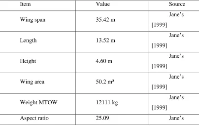
[image:28.612.168.521.197.386.2]A rendering of Global Hawk is shown in Figure 2.7 and some important geometrical, weight and other Global Hawk characteristics are shown in Tables 2.4.
Figure 2.7: Global Hawk UAV [13
Table 2.4: Global Hawk Geometry[6, 14]
Item Value Source
Wing span 35.42 m Jane’s
[1999]
Length 13.52 m Jane’s
[1999]
Height 4.60 m Jane’s
[1999]
Wing area 50.2 m² Jane’s
[1999]
Weight MTOW 12111 kg Jane’s
[1999]
[image:28.612.124.528.454.709.2]17
[1999] Equipped empty
weight 4177 kg
Jane’s [1999]
Take-off weight 11622 kg Jane’s
[1999]
Fuel weight 6583 kg Jane’s
[1999] Mission equipment
weight 900 - 1000 kg
Jane’s [1999]
Detailed geometry characteristics were found through scaling of 3-view drawings. The results were integrated into the detailed geometry input files [6].
2.5.3 Propulsion
[image:29.612.125.530.71.262.2]The Global Hawk engine is the Rolls-Royce 3007H. Major engine characteristics are shown in Table 2.5.
Table 2.5: Global Hawk Propulsion [6]
Item Value Source
Thrust (T-O S/L) 8,290 lbs Jane’s
[1999]
TSFC 0.33 lbm/lb-h Jane’s
[1999]
Weight (Dry) 1,581 lbs Jane’s
[1999]
Length 8.88 ft Jane’s
[1999]
Diameter 3.63 ft Jane’s
18
In addition to the engine, an additional 50 pounds of propulsion weight was added to account for the engine control electronics and actuators, as an assumption [6].
2.5.4 Avionics
[image:30.612.181.508.343.530.2]Global Hawk is known to have an extensive electronics suite. Weights for all of the components are not available. Details of some avionics components, such as INS and data recorders, are found in Global Hawk literature and vendor data sheets. The assumed avionics weights use a fragmentary Master Equipment List (MEL), developed from information generated from Altmann [2002] and Janes [1999], as guidance. Figure 2.8 shows the avionics weights determined for the calibration case.
19
2.5.5 Subsystems
[image:31.612.179.510.261.448.2]Global Hawk has a complex set of subsystems. A list of known subsystems identified by Altmann and Janes is captured in the simple MEL. Unfortunately, no weights data is available for the subsystems. Therefore, no actual weights were used, only assumed subsystem weights and parametric methods. The resulting subsystems weights are shown in Figure 2.9.
Figure 2.9: Global Hawk Subsystems Weights Summary [6]
2.5.6 Structures
20
[image:32.612.175.513.136.327.2]calculated at gross weight, the vertical load is assumed to be 2 G. The Global Hawk structural weight is presented in Figure 2.10.
Figure 2.10: Global Hawk Structural Weight Summary [6]
2.5.7 Payloads
21
2.5.8 Performance
Altmann [2002] provides useful information on the Global Hawk performance and flight envelope limitations. The maximum equivalent airspeed is 175 Keas, and the maximum Mach is approximately Mach 0.7 and the characteristics are shown in Table 2.6.
[image:33.612.176.510.343.543.2]Northrop Grumman advertises the Global Hawk Performance as 24 hours time on station at 1,200 nautical miles radius [Northrop 2003]. This performance estimate was adopted for sizing. Range credit was assumed to be 100 nautical miles for the initial climb to 50,000 feet, and 200 nautical miles from the end of cruise to the final loiter altitude. A half-hour loiter at 5,000 feet was assumed for airfield operations. Altitude and Mach characteristics are shown in Figure 2.11 and Figure 2.12.
22
Figure 2.12: Global Hawk Mach Profile [6]
Table 2.6: Global Hawk– selected performances[6, 14]
Item Value Source
Stall speed 170 km/h Jane’s [1999]
Loiter speed 650 km/h Jane’s [1999]
Max speed 670 km/h Jane’s [1999]
Ceiling 19.80 km Jane’s [1999]
Rate of climb 17.3 m/s Jane’s [1999]
Endurance 38 - 42 h Jane’s [1999]
Range 17 000 km Jane’s [1999]
Runway length 1500 m Jane’s [1999]
Take-off thrust 3.13 kN Jane’s [1999]
Wing loading 231.52 kg/m² Jane’s [1999]
Thrust loading 37.1 kg/N Jane’s [1999]
[image:34.612.112.540.377.657.2]23
2.5.9 Design Technology
[image:35.612.166.483.190.389.2]The weights and performance calibration process resulted design technology levels are shown in Table 2.7.
Table 2.7: Global Hawk Design Technology Levels [6]
Design Item Tech Level (0-1)
Volume Efficiency 0.5
Induced Drag 0.31
Interference Drag 1.0
Wave Drag 0.31
Laminar Flow 0.31
Factor Of Safety 1.0
Weight Growth 0.35
Installation Weight 0.5
2.6 Shadow 200 [6, 15, 16, 17]
2.6.1 Shadow 200 Description
Shadow 200 is a small tactical UAV designed to support line-of-sight battlefield surveillance missions. Initial development began in 1990. However, the technology year was assumed to be 2000 due to the extended development time, significant design evolution, requirements changes, and incorporation of more advanced technologies. Palumbo [2000] is assumed to be the most authoritative source of Shadow 200 data.
24
2.6.2 Geometry Characteristics
[image:36.612.154.536.153.339.2]The Shadow 200 geometry characteristics are shown graphically in Figure 2.13, and numerically in Table 2.8.
[image:36.612.108.527.427.687.2]Figure 2.13: Shadow 200 UAV [18]
Table 2.8: Shadow 200 Geometry Characteristics [6, 15]
Item Value Source
Wing span 12.75 ft
Office of the
Secretary of Defence, Unmanned Aircraft Systems Roadmap 2005-2030.
Weight 165 lbs. empty; 328 lbs. loaded
Length 11.2 ft
Height 3.0 ft
Aspect ratio 7.07
Fuel Capacity 51 lb
Sweep (quarter
chord) 0 º
Payload Capacity 60 lb
65
REFERENCES
1. Zak Sarris “Survey of Uav Applications in Civil Markets (june 2001) “, STN ATLAS-3 Sigma AE and Technical University of Crete, Crete, Greece, 2001 2. Nehme, C.E, Cummings, M.L. and Crandall J.W.” A UAV Mission
Hierarchy”, MIT, HAL2006-9, 2006
3. http://en.wikipedia.org/wiki/Unmanned_aerial_vehicle
4. http://www.thenewatlantis.com/publications/the-paradox-of-military-technology
5. Arjomandi, Maziar. “Classification of Unmanned Aerial Vehicles.” Course material for Mechanical Engineering 3016, University of Adelaide, Australia, 2007.
6. Gundlach, John Frederick IV, \Multi-Disciplinary Design Optimization of Subsonic Fixed-Wing Unmanned Aerial Vehicles Projected Through 2025," Doctoral Dissertation, Virginia Polytechnic Institute and State University, February, 2004.
7. General Atomics, http://www.ga-asi.com/products/aircraft/predator. php April, 2010
8. David Rocky,”Tactical Unmanned Aerial Vehicles,” volume 18, AUVSI magazine, pp.28-30, August 2004.
9. http://www.army-technology.com/projects/rq1-predator/rq1-predator3.html 10. Northrop Grumman, RQ-4A Global Hawk, High Altitude Endurance
66
11. Drezner, Jeffrey A., and Leonard, Robert S., Innovative Development, Global Hawk and Darkstar, Executive Summary and Vol 1-3, RAND Project Air Force, RAND, 2002.
12. Z. Goraj, Ph. Ransom and P. Wagstaff, “From specification and design layout to control law development for unmanned aerial vehicles – lessons learned from past experience”, Proceedings of V European Workshop on Aircraft Design Education, Link¨oping, Sweden, 17–21 (June 2–4, 2002).
13. http://aviationintel.com/2011/12/28/rq-170-sentinel-origins-darkstar-has-grown-up/global-hawk-1/
14. Z. Goraj, A. Frydrychewicz, R. Switkiewicz, B. Hernik, J. Gadomski, T.Goetzendorf-grabowski, M. Figat, St. Suchodolski and W. Chajec “High altitude long endurance unmanned aerial vehicle of a new generation – a design challenge for a low cost, reliable and high performance aircraft”. 2004. Vol. 52(3): 177-178.
15. http://olive-drab.com/idphoto/id_photos_uav_rq7.php
16. Sewoong Jung, “Design and Development of Micro Air Vehicle: Test Bed for Vision-Based Control,” M.S. thesis, Mechanical and Aerospace Engineering Department, University of Florida, pp. 3-10, August 2004.
17. AAI Corporation, http://www.aaicorp.com/pdfs/shadow_200.pdf, April, 2010. 18.
http://www.unmanned.co.uk/unmanned-vehicles-news/unmanned-aerial-vehicles-uav-news/76th-brigade-fields-the-rq-7-shadow-uav/.
19. N. Anton, R. M. Botez and D. Popescu, Stability derivatives for X-31 delta-wing aircraft validated using wind tunnel test data, proceeding of the Institution of Mechanical Engineers, Vol. 225, Part G, Journal of Aerospace Engineering, page 3-4, 2011
20. McCormick, Barnes Warnock, “Aerodynamics, Aeronautics, and Flight Mechanics”, New York: Wiley, (USA) 1979.
21. Roskam, J “Airplane Flight Dynamics and Automatic Flight Controls, Part 1” DARcorporation, 1995.
22. Bandu N. Pamadi, “Performance, Stability, Dynamics and Control of Airplanes”, AIAA 2nd
67
23. M. V. Cook “Flight Dynamics Principles” Butterworth-Heinemann, 2007.
24. Roskam, J and Edward L, Chuan-Tau, Airplane Aerodynamics and Performance, Design, Analysis and Research Corporation (DARcorporation), 120 East Ninth Street, Suite 2 Lawrence, Kansas 66044 (USA) 1997.
25. Hoak, D.E. (1978) USAF Stability and Control DATCOM, Air Force Flight Dynamics Laboratory. Ohio: Wright-Patterson Air Force Base.
26. Rokam, J. (1998). Airplane Flight Dynamics and Automatic Flight Controls (Darcorporation)
![Figure 2.1: Predator UAV [9]](https://thumb-us.123doks.com/thumbv2/123dok_us/8772524.899648/21.612.148.509.422.643/figure-predator-uav.webp)
![Table 2.1: Predator Geometry [6]](https://thumb-us.123doks.com/thumbv2/123dok_us/8772524.899648/22.612.106.557.365.599/table-predator-geometry.webp)
![Table 2.2: Predator Propulsion Characteristics [6]](https://thumb-us.123doks.com/thumbv2/123dok_us/8772524.899648/23.612.176.511.451.624/table-predator-propulsion-characteristics.webp)
![Figure 2.3: Predator Subsystems Weights Summary [6]](https://thumb-us.123doks.com/thumbv2/123dok_us/8772524.899648/24.612.177.509.156.313/figure-predator-subsystems-weights-summary.webp)
![Figure 2.4: Predator Structural Weight Summary [6]](https://thumb-us.123doks.com/thumbv2/123dok_us/8772524.899648/25.612.179.509.70.263/figure-predator-structural-weight-summary.webp)
![Figure 2.6: Predator Velocity Profile [6]](https://thumb-us.123doks.com/thumbv2/123dok_us/8772524.899648/26.612.167.519.352.567/figure-predator-velocity-profile.webp)
![Table 2.3: Predator Design Technology Level [6]](https://thumb-us.123doks.com/thumbv2/123dok_us/8772524.899648/27.612.155.496.106.327/table-predator-design-technology-level.webp)
![Table 2.5: Global Hawk Propulsion [6]](https://thumb-us.123doks.com/thumbv2/123dok_us/8772524.899648/29.612.125.530.71.262/table-global-hawk-propulsion.webp)
![Figure 2.8: Global Hawk Avionics Weights Summary [6]](https://thumb-us.123doks.com/thumbv2/123dok_us/8772524.899648/30.612.181.508.343.530/figure-global-hawk-avionics-weights-summary.webp)
