Hard Disk Drive Mechanism Vibration Damping Using
Disturbance Observer
Mohammad Hossein Farrokhi
*, Faridoon Shabani, Sayyed Hamid Abbasi
School of Electrical and Computer Engineering, Shiraz University, Iran
Copyright © 2014 Horizon Research Publishing All rights reserved.
Abstract
Variety of the usage in Hard Disk Drives relies on the high speed, positioning system precision and reliability of their control mechanisms. Vibration is one of the most important concerns in the control mechanisms due to rotational movement of the HDD drivers and the data head speed so as to keep the performance under control, the movement disturbances should be accurately monitored. Disturbance Observers (DOBs) increase the control system robustness whilst improving the dynamic performance of the systems without employing sophisticated calculations and prerequisite; the plant inverse model calculation is eliminated in this method which empowers the usage and simplifies its implementation. This paper focuses on the suppression of vibration using Disturbance Observer and compares it with PID controller and Intelligent Active Force Controller to figure out the advantages of DOB.Keywords
Disturbance Observer (DOB), Vibration Suppression, Hard Disk Drive (HDD), PID, Fuzzy, Intelligent Active Force Control (IAFC)1. Introduction
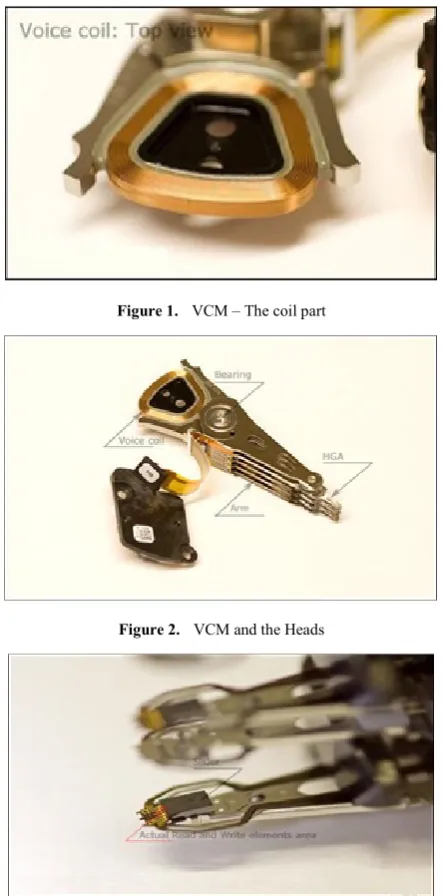
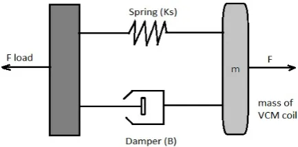
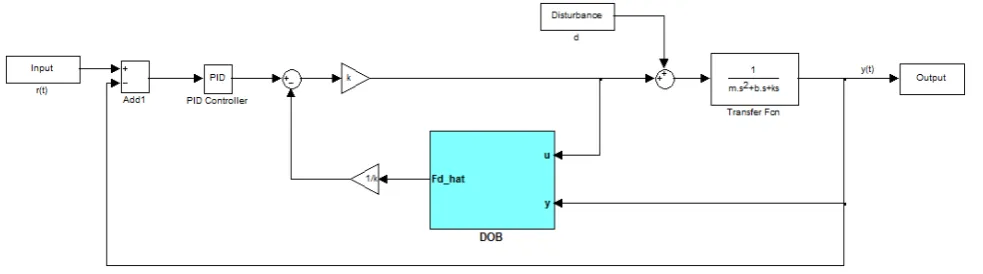
Vibration is one of the most important factors which must be kept under control especially in the mechanical mechanisms. Accuracy, highest access speed and data precision made it the major point of concern in Hard Disk Drives (HDD). The main effects of vibration could be observed in HDD actuators. These actuators consist of especial type of mechanisms named Voice Coil Motors (VCM). By applying the electrical current to the coil of VCM, it becomes excited causing the head movement of the head slider to the desired destination through the suspension mechanism. A typical HDD mechanism is shown in figures1 to 3[1] .Numerous studies have been done on how to boost the controlling performance of the actuation mechanism of HDD.
The improvement of vibration control has been discussed from various aspects and solutions proposed such as by applying several control algorithms, developing new design
[image:1.595.321.543.288.737.2]of actuator, embedding secondary actuator to the system and others [2][3][4][5].
Figure 1. VCM – The coil part
Figure 2. VCM and the Heads
It has been shown by Jintanawan that the vibration increases with higher HDD rotational speed [6]. Wood suggested that the HDD must be stiff enough to suppress the vibration [7]. Thus, this study is conducted to incorporate and apply another new control technique called disturbance observer to the HDD positioning mechanism so that the vibration which is the most important disturbance can be cancelled rapidly, accurately and robustly.
The employed method will be compared with the previous ones and the results will be shown to emphasize on the advantages of the DOB methods. First the mechanical concept is considered as the basis of calculation and modeling in part 2. Intelligent Active Force Controller and Disturbance Observers are introduced in next parts respectively. Part 5 focuses on the comparison of different strategies. The conclusion will be driven according to the results of previous chapter in part.
2. System Modeling
To be able to model the mechanical system, the mathematical model of a linear VCM should be obtained from the Newton’s 2ndLaw which is based on a second order
mass-spring-damper system. It could be represented as follows:
[image:2.595.312.551.266.394.2]∑F = ma (1)
Figure 4. HDD Mechanism, Head Arm
Here, ∑F is the summation of the force vectors applied to the mass of the body, m in the direction of the acceleration, a.
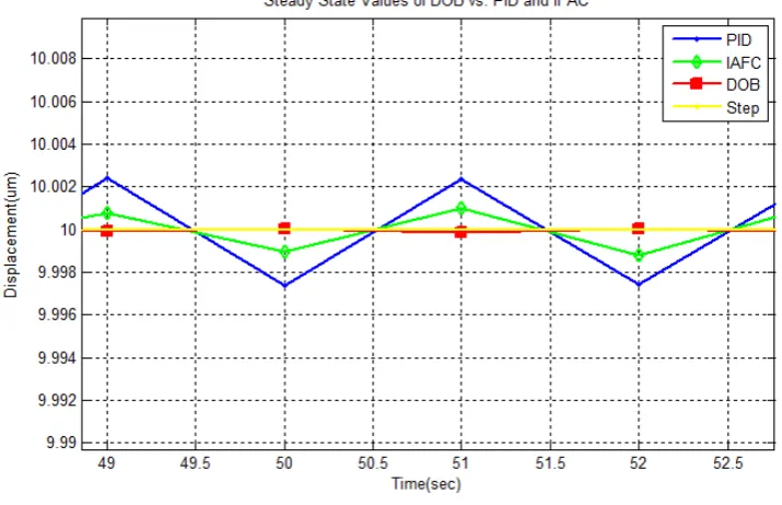
Figure 5. Mass Spring Model of VCM
F- Fload = m(d2x/dt2) (2)
Where:
Fload = Ksx + B(dx/dt) (3) Ksis the spring stiffness, x is the displacement of the spring and B is the damping constant. Also, it is known that:
F = Kfi (4)
Where
Kf = 2Bg l N (5)
m(d2x/dt2)+B(dx/dt) + K
sx= Kfi (6)
m(d2x/dt2)+B(dx/dt) + K
sx = (2Bg l N)I (7)
[image:2.595.69.286.396.588.2]The variables used above are listed in table 1: Table 1. The list of variables
F electromagnetic force by Produced
the current through coil B Damping coefficient Fload Force related to spring and damper Kf Electromagnetic force constant
m Mass of actuator i Coil Current a Acceleration Bg Flux Density
x Displacement l Length of Coil Ks Spring Stiffness N Number of turns
3. Intelligent Active Force Controller
(IAFC)
The Active Force Controller (AFC) method is an algorithm that is able to cancel the disturbances in a dynamic system [8]. The objective of the AFC algorithm is to get the estimated disturbance force, Q* from the measurement of actuator force, F and the acceleration of mass together with the appropriate estimated mass, m*. This relationship is represented by the following equation:
Q* = F – m*a (8)
[image:2.595.69.286.630.737.2]Fuzzy controller is applied so that the value of the estimated mass can be tuned intelligently based on the knowledge that the system has. The fuzzy controller will employ error and the change of error for inputs and the output will be the estimated mass.
4. Disturbance Observer
[image:3.595.58.299.251.374.2]The concept of Disturbance Observers (DOBs) was first proposed by Onishi [10] to improve the performance of tracking controller. They are robust applications of estimation and rejection of external disturbances. A typical structure of a DOB [11] is shown below:
Figure 6. Disturbance Observer Structure
In the mentioned structure, G(s) is the Transfer Function of the system, Go(s) is the nominal model of the system,𝜂𝜂 is unwanted disturbances and Q(s) is a low-pass filter. The design of the low pass filter is one of the main concerns of DOB design. The composition of the output y due to both inputs η and r can be written as the following relation:
y = Go(s) r + (1-Q(s)) Go(s) η (9)
It can be seen that to reject the effects of disturbance, the filter- Q(s)-should be designed such that it would enable selecting a variety of frequencies. It should be selected based on the following relation:
( )
(
)
(
)
0
! ( )
! ! 1 n
i i
mn m
m s
m i i
Q s
s
τ
τ
= −
=
+
∑
(10)Two main factors of the filter are: • τ: the time constant
• m,n: the degrees of numerator and denumerator respectively.
The nominal transfer function Go(s) can be selected as a second order system to enable behaving same as the real system. If the second order system is not good enough for the usage, G(s) can be used as well.
5. Control Strategies’ Comparison
This work focuses on the suppression of vibration using Disturbance Observer and compares it with PID controller and Intelligent Active Force Controller to figure out the advantages of DOB.
In [8], PID, AFC with crude approximation and IAFC have been compared and the advantages of IAFC has been proven. In this paper, PID, IAFC and the DOB ones have been compared to show the benefits of DOB.
The time response of DOB and IAFC has been has been shown in fig. 8. Although the raising time of the IAFC is better than others, the DOB obviously follows the step inputs better because the overshoot has been eliminated and the destination has been achieved smoother.
[image:3.595.62.554.511.648.2]Figure 8. Time Response of DOB vs. IAFS and PID for a 10um step input
The steady state values can also be compared in figure 10. As it can be seen the fluctuation in DOB implementation is negligible in comparison with others.
Figure 9. Steady State values of DOB vs. PID and IAFC
To verify the advantages of the proposed method, the integral error criterions [12] have been used:
𝐼𝐼𝐼𝐼𝐼𝐼= ∫0∞|𝑒𝑒(𝑡𝑡)|𝑑𝑑𝑡𝑡 (11)
𝐼𝐼𝐼𝐼𝐼𝐼= ∫∞|𝑒𝑒(𝑡𝑡)|2𝑑𝑑𝑡𝑡
0 (12)
𝐼𝐼𝐼𝐼𝐼𝐼𝐼𝐼= ∫ 𝑡𝑡0∞ |𝑒𝑒(𝑡𝑡)|𝑑𝑑𝑡𝑡 (13)
𝐼𝐼𝐼𝐼𝐼𝐼𝐼𝐼= ∫ 𝑡𝑡∞ |𝑒𝑒(𝑡𝑡)|2𝑑𝑑𝑡𝑡
0 (14) and the results have been listed in the table below:
0 2 4 6 8 10 12 14
x 10-3 2
3 4 5 6 7 8 9 10 11 12
Time(sec)
D
is
pl
ac
em
ent
(um
)
Time Responce of PID, IAFC, DOB
[image:4.595.135.478.80.315.2] [image:4.595.133.491.379.610.2]Table 2. Integral Error Criterion Comparison of DOB vs. PID and IAFC
IAE ISE ITAE ITSE
PID 0.19857 1.84024 5.75167e-005 2.33869e-004 IAFC 0.13832 1.29794 2.19934e-005 1.19517e-004 DOB 0.08029 0.72904 1.42188e-005 6.81869e-005 The results show the improvement in all four criterions obviously.
[image:5.595.132.477.87.149.2]This is also clear for sinusoidal inputs:
Figure 10. Following Sinusoidal Input-Frequency=300Hz
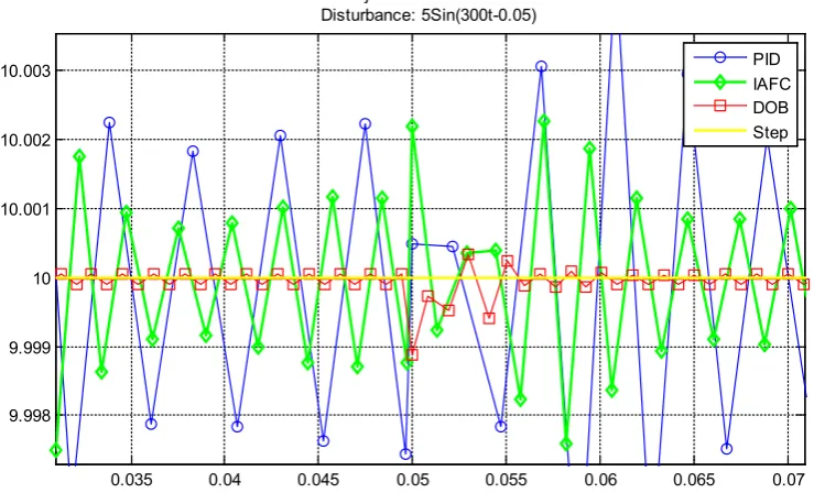
The most important parameter is the reaction of the system to the disturbance. Disturbance rejection has also verified the previous results, a sinusoidal signal has been exerted from t=0.05sec which has the value of 5Sin (300t). The time response also verifies the previous improvements of DOB in disturbance rejection:
Figure 11. Time Response to Sinusoidal Disturbance
0.035 0.04 0.045 0.05 0.055 0.06 0.065 0.07 9.998
9.999 10 10.001 10.002 10.003
Disturbance Rejection of DOB vs. PID and IFAC Disturbance: 5Sin(300t-0.05)
[image:5.595.122.490.191.420.2] [image:5.595.119.489.495.724.2]6. Conclusions
What has been proven through Matlab®/Simuink® Simulation is that the DOB is highly capable of creating smoother and more accurate responses in comparison with PID and IAFC as well. All for integral criterions have been improved and disturbance rejection has been increased while the calculation method became much more simple, causing the need to simpler and consequently chipper hardware for implementation which cannot be withdrawn nowadays.
REFERENCES
[1] http://hddscan.com
[2] K. Peng, B.M. Chen., T.H. Lee, V. Venkataramanan, “Design and implementation of a dual-stage actuated HDD servo system via composite nonlinear control approach”, Mechatronics, 2004. 14, p. 24.
[3] F. Huang, T. Semba, W. Imaino, and F. Lee, “Active Damping in HDD Actuator”, IEEE Transactions On Magnetics, 2001, vol. 37(no. 2), p. 3.
[4] R. Horowitz, Y. Li, K. Oldham, S. Kon, X. Huang, “Dual-stage servo systems and vibration compensation in computer hard disk drives,” in Control Engineering Practice, 2007, vol.15, p. 15.
[5] T. Suthasun, I. Mareels, A. Al-Mamun, “System identification andcontroller design for dual actuated hard disk drive”, Control Engineering Practice, 2004, vol. 12, p. 12. [6] T. Jintanawan, “Vibration of hard disk drive spindle systems
with distrubuted journal bearing forces”, Microsyst. Technol., 2004, vol.10, p.6.
[7] R. Wood, “Future hard disk drive systems”, Journal of magnetism and magnetic materials, 2009, vol.321, p.7. [8] N. S. Mohd Nor, M. Mailah, “Vibration Suppression of Disk
Drive Mechanism Using Intelligent Active Force Control”, 4th International Conference on Mechatronics(ICOM), 2011, Kuala Lumpur, Malaysia.
[9] L.A. Zadeh, “Fuzzy sets”, Information and Control, 1965, vol. 8, pp. 338-353.
[10] K. Onishi, “A New Servo Method in Mechatronics”,Trans Japanese Society of Electrical Engineering, Vol. 107, pp.83-86, 1987.
[11] M. Noorbad, A. Mohammad Shahri, K. Shojaei, B. Tabibian, “A Passivity Atablity Analysis of Disturbance Observer based onTrajectory Tracking Control of Nonhonolomic Weeled Mobile Robot, 2010 IEEE/ASME International Conference on Advanced Intelligent Mechatronics, Montreal, Canada.