International Journal of Emerging Technology and Advanced Engineering
Website: www.ijetae.com (ISSN 2250-2459, Volume 2, Issue 1, January 2012)
61
Development Of Smart Controller For Multisegment-SMC For
Synchronous Reluctance Motor Servo Drive
1
Prof. Ami T Patel
1Assistant Professor, M.G.I.T.E.R, Navsari
1
Abstract— An incremental motion control problem, specified by a trapezoidal speed command profile using multi-segment sliding mode control (MSSMC), is proposed to control synchronous reluctance motor (SRM) servo drive. Since the control gains in the MSSMC are fixed, chattering responses occur due to large external load disturbances. Therefore, a neural network (ANN) is developed to tune the control gains online. A field-oriented control SRM servo drive is implemented and each segment of the multi-segment switching surface is designed so as to match the corresponding part of the trapezoidal speed command profile.
As a consequence, the motor dynamics on the specified segment switching surface have the desired speed or acceleration corresponding to the trapezoidal speed command profile. Theoretical analyses for the proposed ANN-based MSSMC are described in detail. The effectiveness of the proposed SRM servo drive is demonstrated using simulated and experimental results.
Keywords— sliding mode controller, artificial neural network, synchronous reluctance motor, genetic algorithm, non-linear control
I. INTRODUCTION
In the real world in terms of control engineering, there are certain applications such as a robot, an elevator or machine tool drives, in which it is required to move a given load, stop it at a specified position, and hold it there until a subsequent motion command is initiated [1]. This kind of start-stop motion is called incremental motion. In such kind of applications, the sliding line control will be extended to a full sliding trajectory control [2]. So, the designing of the sliding trajectories will depend on the applications for which it is designed & it may be different for different types of applications [4].
The load can be moved to the specified position at a specified time, a desired speed command profile is designed. One of the most commonly used speed command profiles is the trapezoidal speed command profile. It includes three parts: (1) constant acceleration (2) constant speed and (3) constant deceleration.
Due to the system dynamics are itself in a sliding mode at the start, therefore in MS-SMC the reaching phase of the conventional VSC does not exist. Consequently, the robustness of the controlled system can be assured from start to finish.
II. INCREMENTAL MOTION CONTROL OF AN SRM
The incremental motion is to move an object at rest at
time t0 d at time td , and then
stop it. The control process is subjected to the desired velocity and acceleration [5]. So the incremental motion control is performed under velocity control in obedience to a desired velocity profile, whereas stopping is done by position control mode. First select a velocity profile which rapidly changes the load position in discrete step [6]. The velocity profile should satisfy the motion constraints of the system. The velocity and acceleration limitations are generally taken into consideration for the determination of velocity profile [7].
To satisfy the velocity and acceleration limitations, a trapezoidal velocity profile is usually used. The trapezoidal velocity profile is shown in Fig [1]. It can be seen that the trapezoidal velocity profile is composed of three parts: acceleration (from time t0 to t1 ), run (from time t1 to t2), and deceleration (from time t2 to t3).
International Journal of Emerging Technology and Advanced Engineering
Website: www.ijetae.com (ISSN 2250-2459, Volume 2, Issue 1, January 2012)
62 Here, it is not easy to control the motor motion in accordance with the given trapezoidal profile due to the system dynamics are subjected to unknown load perturbations [8]. Therefore, the object here is to design a multi-segment sliding mode controller according to the trapezoidal velocity profile shown in Fig. 1) acceleration segment (acceleration=d1 ); 2) run segment (velocity d); and 3) deceleration segment (deceleration-d2), so that the motor rotates in obedience to the trapezoidal velocity profile despite of the load perturbation [9].
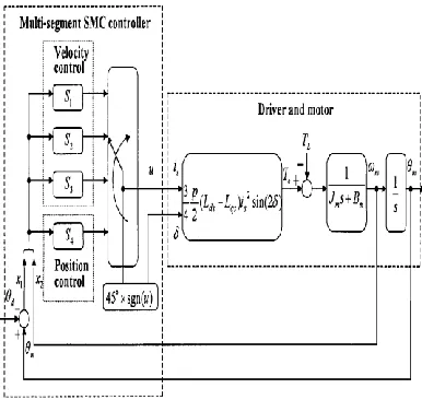
III. BLOCK DIAGRAM OF THE PROPOSED CONTROLLER
The block diagram of the proposed robust control scheme is presented in Figgure(2). The MSSMC is composed of two modes: (i) the speed control mode, represented by the blocks acceleration, constant speed, deceleration & speed control strategy and (ii) the position control mode represented by the blocks position & position control strategy. The speed control mode is used to drive the rotor to the desired position, while the position control mode is used to hold the rotor at the desired position[5].
Fig 2:Multi-segment SMC-based incremental motion control for synchronous reluctance motor system
With a specified rotor position d , which is assumed to be a constant, one first defines the position error and its derivative
---(1)
---(2)
Combining the above (1)
x
1
x
2
---(3)
---(4)
IV.SLIDING CONDITIONS FOR CONTROL MODE
First, the acceleration segment is considered. The parameters h1 and h2 in Equation (6) will be designed to satisfy the sliding condition for the acceleration segment
1 1
s
s
< 0.After a number of manipulations, it is being obtained:
L m m d dT
x
h
K
h
K
B
J
x
s
x
x
x
s
s
s
2 2 1 1 1 1 2 1 2 2 1 1 1 1 11
1
1
--- (5)Accordingly, if the following gains, hl and h2, are given, the sliding condition for the acceleration segment described in (6) is satisfied:
h1 = α1 if s1x2 > 0
-α1 if s1x2 < 0 --- (6)
h2 = β1 if s1 > 0
-β1 if s1 < 0 --- (7)
Where, α1 > 1 1
K
T
J
m Ld
and β1> 1K
B
mNote that acceleration segment control is used to accelerate a system at rest to the desired speed with an acceleration αd1 during the time period [t0, tl]. The rotor speed will reach the expected run value wd at time tl. At t = t1, control will be switched to the run segment s2.
m d m
x
x
2 1 m m e m mJ
T
J
T
x
J
B
x
L
[image:2.612.48.241.405.588.2]International Journal of Emerging Technology and Advanced Engineering
Website: www.ijetae.com (ISSN 2250-2459, Volume 2, Issue 1, January 2012)
63 Likewise, to maintain the rotor dynamics sliding on the run segment [5], one has to ensure that the sliding condition of the run segment
s
2s
2< 0 and the gains of the sliding mode controller h1 and h2 are designed as:h1 = -α2 if s2 > 0 --- (8)
α2 if s2 < 0
h2 = -β2 if s2x2 > 0 --- (9)
β2 if s2x2 < 0
Where, α2> 1
K
T
Land β2>
1
K
B
m
After running with the desired speed wr* during the time period [t1, t2], control has to be switched to the deceleration segment s3 at t= t2. The following control gains ensure the
sliding condition of the deceleration segment
s
3s
3< 0:h1 = -α3 if s3x2 > 0 --- (10)
α3 if s3x2 < 0
h2 = -β3 if s3 > 0 --- (11)
β3 if s3 < 0
Where, α3 >
1 2
K
J
T
L
d mand β3>
1
K
B
mAfter the speed control mode is completed, the rotor has been moved to the desired position θd. Similar to the speed control mode, the control object is to maintain the sliding condition of the position control mode,
s
4s
4 < 0. To this end, the following control law is proposed:u = k1 (h1x1 + h2x2 +u0) --- (12)
Where,
h1 = -α4 if s4x1 > 0 --- (13)
α4 if s4x1 < 0
h2 = -β4 if s4x2 > 0 --- (14)
β4 if s4x2 < 0
u0 = -T0 if s4 > 0 --- (15)
T0 if s4 < 0
With α4 > 0, β4> 1
K
cJ
B
m
mand T0 >
1
K
T
LV. SIMULATION SCHEME OF THE CONVENTIONAL CONTROL
The control object here is to rotate the rotor 4Π rad in 0.6s following the trapezoidal speed command profile with αd1 = 165.654 rad/s2, αd2 = -165.654 rad/s2, wd = 30 rad/s, t1 = 0.1811 s, t2 = 0.4189 s and t3 = 0.6 s. Fig(4) shows the simulation model for the closed loop response.
Fig:4: Simulation closed loop response of MS-SMC with SRM]
IV. NEURAL NETWORK BASED INTELLIGENT CONTROL
International Journal of Emerging Technology and Advanced Engineering
Website: www.ijetae.com (ISSN 2250-2459, Volume 2, Issue 1, January 2012)
64 Back propagation is the most popular training method for a multi-layer feed-forward network; therefore the standard network trained by this algorithm is often called the BP network. It is generalization of the delta learning rule developed by Widraw and Haft for Adaline training [11]. Here aim is to train the ANN with the help of BKP algorithm to reduce chattering in the sliding mode. The network structure is given in figure (5).Code for the training of ANN is described below.
net=newff(minmax(p1),[1,20],{'tansig','purelin'},'traingdm' )net.trainParam.show = 15;
net.trainParam.lr = 0.125;
net.trainParam.epochs = 3000;
net.trainParam.goal = 1e-3;
[net,tr]=train(net,p1,t1);
a=sim(net,p1);
gensim(net)
Fig:5 : Artificial neural network model
After training of the ANN conventional MS-SMC is replaced by the neuro-MS-SMC which is discussed in the results.
VII.GENETIC ALGORITHM BASED ADVANCED CONTROL
The proposed GA-based MSSMC is shown in Figure. Compared to the control scheme shown in Figure 4 & 5, the control gains of the speed control and the position control strategies shown in equations (14) and (12), respectively, are tuned off-line using the GA. The inputs of the GA are the switching variable s, its derivative and the torque current command for the evaluation of the fitness function.
Represent the problem variable domain as a chromosome of a fixed length, choose the size of a chromosome of population popsize, crossover probability pcross, the mutation probability pm, and the termination criteria maxgen.(1) population size = popsize =10 (2) No. of generation = maxgen =10 (3) Crossover probability = pcross = 0.8 (4) Mutation probability = pm =0.01
By randomly generating an initial population of chromosomes within the specified upper & lower limit values of the parameters. In this work 6 control gains (parameters), [α1, β1, α2, β2, α3, β3] of the speed control mode and 3 control gains (parameters), [α4, β4 and fo,] of the position control strategies are being tuned with the help of GA. And here popsize =10 is defined. So, the initial populations of phenotypes are represented in the form of [10 ×9] matrix.
The specified range of control gains αi , βi (i=1, ...., 4) and fo for this work is as follow:
α1=[10 25], α2=[5 25], α3=[10 25], α4=[200 550] , β1=[5 15], β2=[5 20], β3=[5 15], β4=[100 300], fo=[2 20]
Defining a fitness function to measure the performance, or fitness, of an individual chromosome in the problem domain. The fitness function establishes the basis for selecting chromosomes that will be mated during reproduction. The fitness function followed from [11] Ffit is
defined as follows:
|
|
1
50
1
1*qs i
i
i
W
f
S
Ffit
Where, i= 1, ----4.
Where, Si= sliding segments,
f
i = is the derivative of Si,, and iqs*
is the torque current command. These three inputs of the GA are received from the model.
VIII.SIMULATION RESULTS
To demonstrate the effectiveness of the proposed control strategy, simulations are first done using MATLAB software. The characteristics of the SynRM are given in the Appendix. The objective is to rotate the motor 4π radians in 0.6 sec obeying the trapezoidal velocity profile with
International Journal of Emerging Technology and Advanced Engineering
Website: www.ijetae.com (ISSN 2250-2459, Volume 2, Issue 1, January 2012)
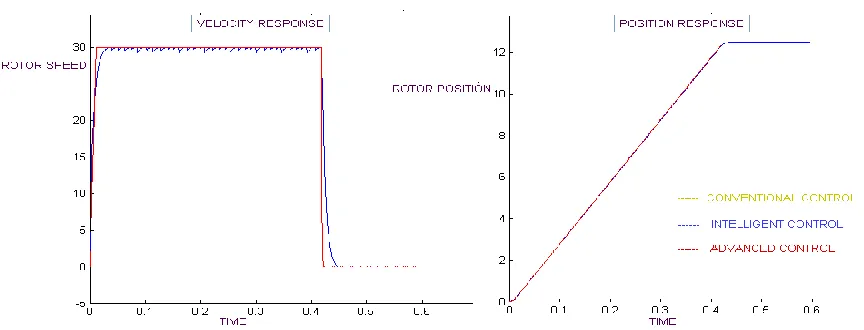
65 Because the system dynamics on the conventional sliding mode converge at the rate of e-ct. . c=5 is set to have the settling time of 0.6 sec. fig (6) shows the Velocity and Position response of the conventional control respectively. This method produces chattering.
[image:5.612.97.529.215.380.2]Our aim is to reduce chattering in such a way that the system is robust to the parameter perturbation and external load disturbance.
Fig: 6 :- Performance comparison of controller techniques.
Fig (6) also shows the reduction of the chattering with the help of artificial neural network. In this case the multi-segment SMC is replaced by the fully neural network. But to make the system more robustly responding, genetic algorithm tunes the parameters in such a way that the chattering can be reduced. Further it is modified by genetic algorithm (advanced control) shown in fig (6).
As a future work this controller can be applied to any other drive system with higher rating where parameter variation effect can be studied. Neural Network training with genetic algorithm (On line control) can be incorporated to this controller to make it more efficient and robust.
IX.CONCLUSION AND FUTURE ENHANCEMENT
This study has presented the multi-segment sliding mode control according to the trapezoidal velocity profile. It has shown that the dynamics of the multi-segment sliding mode controlled SynRM fully satisfied the desired velocity and acceleration of a motor in the velocity control mode of the incremental motion, And it is invariant to the perturbations. It has also shown that the proposed control techniques are more suitable than the
conventional MS-SMC for the incremental motion control of the SynRM.
X.APPENDIX
Motor data:-
Rated Power=1120W
Rated Voltage=3 AC
Rated Current=6.6A
Direct Inductance Lds=135mH
Quadrature Inductance Lqs=50mH
Stator resistance Rs=0.91
Inertia Jm=0.01 N.m/S2
Viscous coefficient Bm=0.002 Nm/S
International Journal of Emerging Technology and Advanced Engineering
Website: www.ijetae.com (ISSN 2250-2459, Volume 2, Issue 1, January 2012)
66
References:
[1] Peyman Niazi, Member, IEEE, and Hamid A. Toliyat, Senior Member, IEEE, ―Online Parameter Estimation of Permanent-Magnet Assisted Synchronous Reluctance Motor,‖ IEEE Trans.Ind. Applicat., vol.43, pp. 609–615, 2007.
[2] Hwang-Bin Lim; Jung-Ho Lee, ―The Evaluation of Online Observer System of Synchronous Reluctance Motor Using a Coupled Transient FEM and Preisach Model‖ IEEE Trans. Ind. Applicat., vol. 44, pp. 4139 – 4142,2008
[3] Chien-An Chen ; Wen-Bin Lin ; Huann-Keng Chiang, ―Design and implementation sliding mode controller based on radial basis function neural network for synchronous reluctance motor,‖IEEE Trans. Ind.Applicat., pp. 281 - 286, 2009.
[4] dong xu; dongbin zhao; jianqiang yi; xiangmin tan; ―trajectory tracking control of omnidirectional wheeled mobile manipulators: robust neural network-based sliding mode approach ,‖ in proc.ieee/ias annu. Meet., vol. 39, 2009, pp. 788 - 799.
[5] Liangyong Wang; Tianyou Chai; Lianfei Zhai; ―Neural-Network-Based Terminal Sliding-Mode Control of Robotic Manipulators Including Actuator Dynamics,‖ IEEE Trans. Ind. Applicat., vol. 56, pp. 3296 - 3304, Sept./Oct. 2009.
[6] T. H. Liu and M. T. Lin, ―A fuzzy sliding-mode controller design for a synchronous reluctance motor drive,‖ IEEE Trans. Aerospace Electron. Syst., vol. 32, pp. 1065–1076, July 2006.
[7] R. Lagerquist, I. Boldea, and T. J. E. Miller, ―Sensorless control of the synchronous reluctance motor,‖ IEEE Trans. Ind. Applicat., vol. 30, pp. 673–681, May/June 2004.
[8] Modern power electronics & AC drives By : Bimal K. Bose
[9] Electric motor drives Modeling, Analysis, and control By R.Krishnan
[10] sliding mode theory & application By Christopher Edwards & Sarah k.spurgeon.