Copyright © 2019 Authors. This is an open access article distributed under the Creative Commons Attribution License, which permits unrestricted use, distribution, and reproduction in any medium, provided the original work is properly cited.
International Journal of Engineering & Technology
Website: www.sciencepubco.com/index.php/IJET
Research paper
Optimization of Injection Molding Parameters for
WC-TaC-6Co
M. Prathabrao1,*, S.Y.M. Amin2, M.H.I. Ibrahim3, M.H. Othman4, S.N.A. Shahbudin5
1Advance Manufacturing and Material Center (AMMC), Faculty of Mechanical and Manufacturing,
Universiti Tun Hussein Onn Malaysia, 86400 Parit Raja, Batu Pahat Johor, Malaysia *Corresponding author E-mail: [email protected]
Abstract
The main purpose of this paper is to optimize the injection moulding parameters of WC-Co with TaC as Grain Growth Inhibitor (GGI), through Design of Experiment – Taguchi Method. The selected responses that need to be controlled are shrinkage and warpage. The parameters that were taken into considerations were GGI percentage, injection temperature, injection pressure and injection speed. In this study, L9 (34) orthogonal array from Taguchi Method was chosen as experimental setup and the responses were analyzed using Minitab
version 16. Best parameters combinations chosen are, GGI (0.8 wt. % and 1.2 wt. %), injection temperature (145°C), injection pressure (45% and 55%) and injection speed (40%) for minimal shrinkage and warpage. Based on these findings, it is concluded that by controlling the optimum parameter setting, best quality of desired product can be easily achieved and maintained throughout the process.
Keywords: Grain growth inhibitor (GGI); Metal injection molding (MIM); Parameter optimization; Taguchi method
1.
Introduction
Metal injection molding (MIM) is divided into four major technological phases: mixing, injection molding, debinding and sintering. Opti-mization of injection parameters is necessary in producing high-quality green components before going through the debinding and sintering processes [1]. There are many injection-molding parameters that have some effect on the properties of green parts and it is gaining much interest among researchers because it minimizes defects, cost and obtain high efficiency in the planning or experiments. Therefore, it is necessary to use one of the design of experiment (DOE) methods for the kind of experimental work where there are many inputs. DOE technique brings some researchers to identify the quality parameter need to be control, for example Ji et al. [2] measure the effects of sintering factors on the properties of sintered parts. Khairur et al. [3] has been using classical Design of Experiment technique to study the effects of injection parameters on the green part quality characteristics such as green density, green strength and green defects.
The Taguchi method optimizes injection parameters by considering the surface quality and the strength of the green compact, thus mini-mizing the number of experiments needed to compare to the trial-and-error method. There are few researchers that using Taguchi as a medium tool to optimize their parameter including Ghani et al. [4], Ahmad et al. [5] , Chen et al. [6], Tuncay et al. [7] and Oktem et al.
[8]. A component is considered high density when it has better strength and limitless defect [9]. The mold temperature and packing time have the greatest influence on green compact surface quality, as reported by Jamaludin et al. [10]. Tatt [11] also reported the mold temper-ature has the greatest influence on green compact surface quality, density and strength. In this study, orthogonal array experiment of L9
were created to find the optimum levels of process parameters and to find the optimum density, shrinkage, warpage and porosity in green part.
2. Methodology
2.1. Material selection and sample preparation
Table 1: Milling parameters Milling type Dry Rotation speed (rpm) 200 Milling time (min) 90
2.1.1. Cemented Tungsten Carbide (WC-6Co)
Norgren et al. classified production of cemented carbides for metal cutting and rock drilling tools is a fast growing segment in industry [12]. German and Bose reported that tungsten carbide dominates in MIM applications, accounting for around half of the global production [13].
Previous studies by Fayyaz et al., Amin et al. and Jiang et al. applied this type of metal powder [14]–[16]. This trendy material was recognized among the researchers according to its major advantages when compared to other metal powders. The points below portrays the summary of why WC-Co metal powder was selected to be applied in this research:
a. Extremely high hardness and toughness b. Excellent wear resistance
c. Superior abrasion resistance d. High melting temperature e. Good thermal conductivity
Previous study of Amin et al. and Fayyaz et al. applied WC-Co with mean size D50=8.6µm supplied by Eurotungstene Co. [15], [17].
Details characteristics or properties of this metal powder are well presented in Table 2, Table 3, and Figure 1. Noted that the same source of powder was used in this present research. There are some points that must be highlighted regarding this previous study. It were listed as below:
a. The true pycnometer density of powder is valued at 12.7221 g/cm3. This property was too important to be achieved or nearly achieved
for green part.
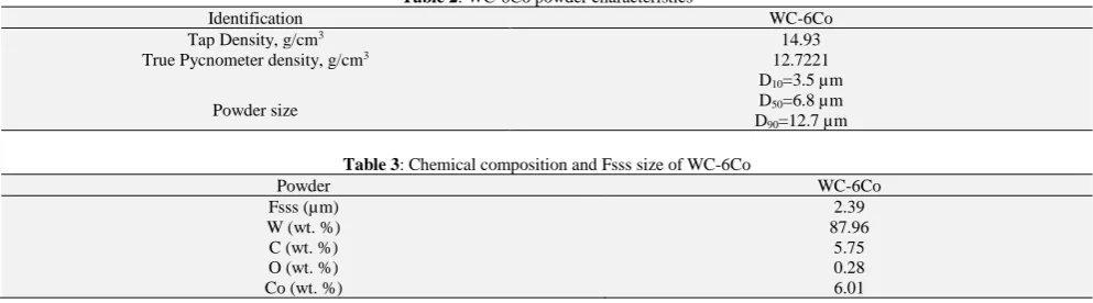
b. Figure 3.2 shows the morphology of WC-Co metal powder. It clearly shows the irregular shape particles. The images was made as a guideline in purpose to conducting the morphological for the present research.
c. Displayed in Table 2 list of chemical compositions and weight percentage of element contains in WC-6Co. Therefore, the present work must be obtaining the same elements due to the same type and source of getting the metal powder.
d. The Critical Powder Volume Concentrations (CPVC) for as received WC-Co is valued by 47 %. The CPVC value of a powder is too crucial in determining the range of the appropriate powder loading of a MIM technology [13]. Recommended that, the optimum powder loading must be 2 % to 5 % lower than CPVC. In this regards, the powder loading applied for this present research is in the range of 42 vol. % to 45 vol. %.
[image:2.595.56.553.444.582.2]e. The same batch of WC-6Co metal powder was used in this present research. However, the morphology of the powder was again observed for confirming the elements of powder.
Table 2: WC-6Co powder characteristics
Identification WC-6Co
Tap Density, g/cm3 14.93
True Pycnometer density, g/cm3 12.7221
Powder size
D10=3.5 µm D50=6.8 µm D90=12.7 µm
Table 3: Chemical composition and Fsss size of WC-6Co
Powder WC-6Co
Fsss (µm) 2.39
W (wt. %) 87.96
C (wt. %) 5.75
O (wt. %) 0.28
Co (wt. %) 6.01
2.1.2. Tantalum Carbide (TaC)
The size of carbide grains highly effects the mechanical properties of cemented carbide. The doping of a small amount of transition metal carbide is effective to suppress the grain growth of carbide grains in WC-Co cemented carbides. Previous studies by Fayyaz et al., Peng et al., Pötschke et al., and Fabijanić et al. studied about different type of GGI tailored with WC-Co [14], [18]–[20]. Their primary task is to preserve the particle size of starting powders in the sintered product, while at the same time influencing the properties of consolidated samples, decreasing density, increasing the value of hardness at room temperature and also affecting toughness, hardness and creep re-sistances at elevated temperatures [20].
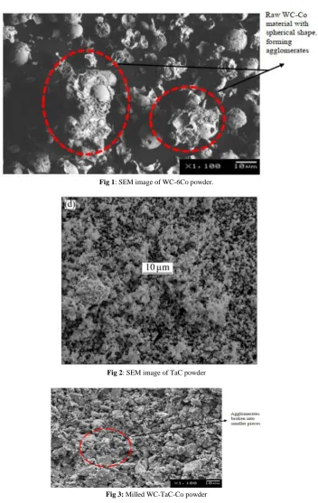
[image:2.595.225.386.715.771.2]Siwak and Garbiec [21] studied the effects of TaC additives on the densification, microstructure and some mechanical properties in WC-Co cermet compacts. Meanwhile, van der Merwe and Sacks [22] investigated addition of TaC on friction and dry sliding wear of WC-6WC-Co cemented carbides against steel counter faces. Detailed characteristics of this metal powder are presented in Table 4 and Figure 2.
Table 4: TaC powder characteristics [21]
Powder TaC
Average Particle
Di-ameter (µm) 1.09 Theoretical Density
Fig 1: SEM image of WC-6Co powder.
Fig 2: SEM image of TaC powder
Fig 3: Milled WC-TaC-Co powder
2.2. Taguchi Method
In this study, L9 (34) orthogonal array consisting of 9 experiment trials and 4 column is used as DOE. The parameters that are involved are
[image:3.595.131.484.52.610.2]GGI percentage (A), injection temperature (B), injection pressure (C) and injection speed (D) as shown in Table 5. By using Statistical software-Minitab version 16, the data of signal to noise ratios were obtained to gain the optimized factors, the signal to noise response graph was constructed to find the optimum level from four factors and three levels based on the data taken from shrinkage and warpage.
Table 5: Injection Parameters for three level Taguchi Design GGI (%) Injection Temperature (°C) Injection Pressure (bar)
Injection Speed (%)
Level A B C D
0 0.4 140 45 30
1 0.8 145 50 35
[image:3.595.57.552.702.779.2]Taguchi’s S/N ratio for smaller-the-better quality characteristics is usually for an undesired output, for example, defects like shrinkage and warpage, particulates in deposition processes, porosity and unwanted by-product or side effect. The actual equation for calculating the signal-to-noise ratio for the smaller-the-better quality characteristic is a logarithmic function based on the mean square deviation [3]. The S/N ratio can be written as:
S/N=10 𝐿𝑜𝑔𝑀𝑆𝐷 (1)
The mean square deviation for a smaller-the-better characteristics is:
𝑀𝑆𝐷 =
𝑦12+ 𝑦22+⋯𝑦𝑛2𝑛 (2)
We can rewrite the S/N equation as:
𝑆 𝑁
⁄
= −10 log |
𝑦1 2+ 𝑦22+⋯+𝑦𝑛2𝑛
|
(3)3. Results
3.1. Shrinkage and Warpage
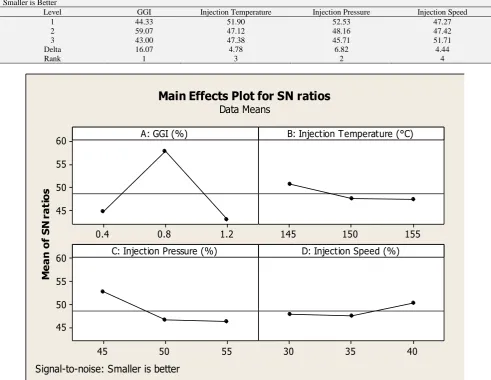
[image:4.595.59.551.374.754.2]Based on the graph in Figure 4 and Table 6, it can be observed for shrinkage the highest value in each factors are, 0.8 wt. % of GGI, 145°C of injection temperature, 45% injection pressure and 40% injection speed. Shrinkage occurs because binders can be removed more easily along shorter distance. When melted granulates flow through a micro channel the flow resistance is higher. This high flow resistance obstructs the entrance of metal particles but the polymer binder in the melt can flow relatively well in the narrow cavity or small part. Injection temperature (145°C) and injection pressure (45%) is suitable for the binders to flow through easily in the mould part and the higher the injection speed (40%) makes the powder and binder to fill up the mold faster. Thus, there will be less defect in the green part.
Table 6: Response table for S/N Values of shrinkage Smaller is Better
Level GGI Injection Temperature Injection Pressure Injection Speed
1 44.33 51.90 52.53 47.27
2 59.07 47.12 48.16 47.42
3 43.00 47.38 45.71 51.71
Delta 16.07 4.78 6.82 4.44
Rank 1 3 2 4
Fig. 4: Main effects plot (data means) for S/N ratio – Shrinkage
1.2 0.8
0.4 60
55
50
45
155 150
145
55 50
45 60
55
50
45
40 35
30 A: GGI (%)
M
e
a
n
o
f
S
N
r
a
ti
o
s
B: Injection Temperature (°C)
C: Injection Pressure (%) D: Injection Speed (%)
Main Effects Plot for SN ratios
Data Means
Fig. 5: Main effects plot (data means) for S/N ratio – Warpage
Based on the Figure 5 and Table 7, it can be concluded for warpage, the highest value in each factors are 1.2 wt. % GGI. 145°C of injection temperature, 55% of injection pressure and 40% of injection speed. As can be seen in Table 7, injection temperature, pressure, and speed shows same ranks as it contributes equally. In other word, it can be concluded, the parameters have no significant effect on warpage response. Warping is the results of the different shrinkage. The thickness of specimen was measured at 10 different places. Narrow channels are filled first with relatively higher amount of plastic materials and followed by metal powders, thus injection temperature (145°C) must be lower to prevent warpage occur in the green part. It is proven that, less warpage will occur if pressure (55%) and speed (40%) is higher.
Table 7: Response table for S/N Values for warpage Smaller is Better
Level GGI Injection Temperature Injection Pressure Injection Speed
1 -7.959 -7.854 -7.854 -7.865
2 -7.819 -7.854 -7.856 -7.854
3 -7.795 -7.856 -7.854 -7.854
Delta 0.164 0.012 0.012 0.012
Rank 1 3 3 3
4. Conclusion
This paper summarizes experimental investigations carried out on optimization injection process via L9 (34) Taguchi Method for WC-Co
with TaC as grain growth inhibitor as a feedstock in MIM. It can be concluded that, for shrinkage, the best optimized parameter are GGI (0.8 wt. %), injection temperature (145°C), injection pressure (45%) and injection speed (40%). As for warpage, the best optimized param-eters are GGI (1.2 wt. %), injection temperature (145°C), injection pressure (55%) and injection speed (40%). Hopefully this research can be a guideline for debinding and sintering process to be done in near future.
Acknowledgement
The authors would like to thank the Ministry of Higher Education Malaysia and Universiti Tun Hussein Onn Malaysia’s Research Man-agement Centre (RMC) for the FRGS-1590 and GPPS-U828 grants and laboratory apparatus provided at AMMC lab.
References
[1] M. H. I. Ibrahim, N. Muhammad, A. B. Sulong, K. R. Jamaluin, S. Ahmat, and N. H. M. Nor, “Water Atomised Stainless Steel Powder for Micro Metal Injection Molding : Optimization of Rheological Properties,” J. Mech. Mater. Eng., no. December, pp. 1–8, 2009.
[2] C. H. Ji, N. H. Loh, K. A. Khor, and S. B. Tor, “Sintering study of 316L stainless steel metal injection molding parts using Taguchi method: final density,” Mater. Sci. Eng. A, vol. 311, no. 1–2, pp. 74–82, 2001.
[3] K. R. Jamaludin, N. Muhamad, M. N. A. Rahman, and S. Yulis, “Analysis of Variance on the Metal Injection molding parameters using a bimodal particle size distribution feedstock.”
[4] J. A. Ghani, I. A. Choudhury, and H. H. Hassan, “Application of Taguchi method in the optimization of end milling parameters,” J. Mater. Process. Technol., vol. 145, no. 1, pp. 84–92, 2004.
1.2 0.8
0.4 -7.80
-7.84
-7.88
-7.92
-7.96
155 150
145
55 50
45 -7.80
-7.84
-7.88
-7.92
-7.96
40 35
30 A: GGI (%)
M
e
a
n
o
f
S
N
r
a
ti
o
s
B: Injection Temperature (°C)
C: Injection Pressure (%) D: Injection Speed (%)
Main Effects Plot for SN ratios
Data Means
[image:5.595.56.554.458.523.2][5] S. Ahmad, N. Muhamad, A. Muchtar, J. Sahari, K. R. Jamaludin, M. H. I. Ibrahim, and N. H. M. Nor, “Optimisation of processing parameters of titanium foams using Taguchi method for compressive strength,” in Key Engineering Materials, 2010, vol. 447, pp. 671–675.
[6] R. S. Chen, H. H. Lee, and C. Y. Yu, “Application of Taguchi’s method on the optimal process design of an injection molded PC/PBT automobile bumper,” Compos. Struct., vol. 39, no. 3–4, pp. 209–214, 1997.
[7] T. Erzurumlu and B. Ozcelik, “Minimization of warpage and sink index in injection-molded thermoplastic parts using Taguchi optimization method,” Mater. Des., vol. 27, no. 10, pp. 853–861, 2006.
[8] H. Oktem, T. Erzurumlu, and I. Uzman, “Application of Taguchi optimization technique in determining plastic injection molding process parameters for a thin-shell part,” Mater. Des., vol. 28, no. 4, pp. 1271–1278, 2007.
[9] Y. Li, L. Li, and K. A. Khalil, “Effect of powder loading on metal injection molding stainless steels,” J. Mater. Process. Technol., vol. 183, no. 2–3, pp. 432–439, 2007.
[10] K. R. Jamaludin, N. Muhamad, M. N. A. Rahman, S. Ahmad, M. H. I. Ibrahim, and N. H. M. Nor, “Optimizing the injection parameter of water atomised SS316L powder with design of experiment method for best sintered density,” Chiang Mai J. Sci, vol. 36, no. 3, pp. 349–358, 2009. [11] T. K. Tatt, “Optimization parameters of injection process by using Taghuci method for metal injection molding (MIM) MSc,” Univ. Kebangs.
Malaysia, 2009.
[12] S. Norgren, J. García, A. Blomqvist, and L. Yin, “Trends in the P/M hard metal industry,” Int. J. Refract. Met. Hard Mater., vol. 48, pp. 31–45, 2015. [13] R. M. German and A. Bose, “Powder Injection Molding of Metal and Ceramics: Metal Powder Industries Federation,” Princeton, NJ, 1997. [14] A. Fayyaz, N. Muhamad, A. B. Sulong, J. Rajabi, and Y. N. Wong, “Fabrication of cemented tungsten carbide components by micro-powder injection
moulding,” J. Mater. Process. Technol., vol. 214, no. 7, pp. 1436–1444, 2014.
[15] S. Y. M. Amin, N. Muhamad, K. R. Jamaludin, A. Fayyaza, and H. S. Yunn, “Ball Milling of WC-Co Powder as Injection Molding Feedstock,” Appl. Mech. Mater., vol. 110–116, pp. 1425–1430, 2011.
[16] A. Jiang, B. Wen, and Q. Li, “Fabrication of WC-TiC-6 % Co Hard Metals by micro-powder injection moulding,” no. Iwmecs, pp. 543–547, 2015. [17] A. Fayyaz, N. Muhamad, A. B. Sulong, H. S. Yunn, S. Y. M. Amin, and J. Rajabi, “Micro-powder injection molding of cemented tungsten carbide:
Feedstock preparation and properties,” Ceram. Int., vol. 41, no. 3, pp. 3605–3612, 2015.
[18] Y. Peng, C. Buchegger, W. Lengauer, Y. Du, and P. Zhou, “Solubilities of grain-growth inhibitors in WC-Co-based cemented carbides: Thermodynamic calculations compared to experimental data,” Int. J. Refract. Met. Hard Mater., vol. 61, pp. 121–127, 2016.
[19] J. Pötschke, V. Richter, T. Gestrich, T. Säuberlich, and J. A. Meese-Marktscheffel, “Grain growth inhibition in ultrafine hardmetals,” Int. J. Refract. Met. Hard Mater., vol. 66, pp. 95–104, 2017.
[20] T. Aleksandrov Fabijanić, S. Jakovljević, M. Franz, and I. Jeren, “Influence of Grain Growth Inhibitors and Powder Size on the Properties of Ultrafine and Nanostructured Cemented Carbides Sintered in Hydrogen,” Metals (Basel)., vol. 6, no. 9, p. 198, 2016.
[21] P. SIWAK and D. GARBIEC, “Microstructure and mechanical properties of WC–Co, WC–Co–Cr3C2and WC–Co–TaC cermets fabricated by spark plasma sintering,” Trans. Nonferrous Met. Soc. China (English Ed., vol. 26, no. 10, pp. 2641–2646, 2016.