936
CONTEXT-AWARE SOFTWARE SYSTEMS:
TOWARD A DIAGRAMMATIC MODELING FOUNDATION
SABAH AL-FEDAGHI
Assoc. Prof., Department of Computer Engineering, KUWAIT UNIVERSITY, KUWAIT E-mail: [email protected]
ABSTRACT
Over the last three decades, research in the area of context-aware computing has involved many different prototypes, systems, and solutions. Context-aware computing is concerned with the acquisition of context, the abstraction and understanding of context, and application behavior based on recognized context. One of the challenges of context-aware computing is difficulty in rethinking of domain models. The problem discussed in this paper is how to model a “context” and how this model influences the design of information system software. In the software development life cycle, this problem falls in the phase of requirements analysis and design. This paper proposes a new approach to modeling “context” in the design of information systems, using flow-based diagrams that could play a role in the design of context-aware systems.
Keywords: Context awareness, conceptual model, information system design, diagrammatic modeling language
1.
INTRODUCTIONIn the design of software systems, the ability to react to context disturbances and perturbations is essential [1]. The notion of flexibility reflects adaptability to changes in a system’s environment such as variations in time, location, weather, or performance requirements. According to Regev et al. [2], flexibility refers to the capability, in response to contextual factors, to produce only those aspects that need to be changed without completely replacing the system. “Thus, process flexibility consists of an extrinsic trigger for change and intrinsic change mechanisms toward self-organization” [3].
1.1 Context and context awareness
The notion of context usually refers to ambience, association, background, circumstance, condition, connection, frame of reference, framework, relation, and situation [4]. “The term ‘context’ is used to characterize, abstract and classify constraints, situation-related requirements, a resultant profile of information need and necessary information flow” [5]. An often-cited definition is “Context is any information that can be used to characterize the situation of an entity. An entity is a person, place or object that is considered relevant to the interaction between a user and an
application, including the user and applications themselves” [6]. An under-standing of context would help designers and system architects use this important concept more effectively in context-aware computing [7].
Context can be categorized as external and internal [8]-[9], as physical and logical [10], as computing, user, and physical [11], and as time [12]. Dadu [13] classifies Context as (i) Computing
Context: Network connectivity, Communication
cost, Comm. Bandwidth, and Nearby resources; (ii)
User Context: User profile/preference, User
mood/behavior, and Other’s presence; (iii)
Environmental Context: Lighting, Noise level,
Traffic conditions, and Weather; and (iv) Physical
Context: Time, Date, and Location
Context awareness is a central concept for
improving process flexibility. The term
context-aware is first used to describe the surrounding
937 significant number of prototypes, systems, and solutions [18].
1.2 Context awareness in computing
In computing, context-awareness refers to the ability of the system to detect, interpret and respond to aspects of the local environment. It enhances these systems with a sense of reality and make them know about the aspects of the environment relevant to the involved application [19].
Context aware systems are concerned with the
acquisition of context (e.g., using sensors to perceive a situation), the abstraction and understanding of context (e.g., matching a perceived sensory stimulus to a context), and application behaviour based on the recognized context (e.g., triggering actions based on context) [20] (Italics added).
Sensing mechanisms can be based on events (monitoring the environment for occurrence of events) and continuous sensing (e.g., mobile phones).
Currently, context awareness is considered an important feature in most computing applications, especially in interactive and smart environments. Advances in telecommunications and information technologies have enabled distributed sensing and tracking to solve a wide range of context-aware environment problems [21]. Market research has shown a significant growth of sensor deployments that continuously generate enormous amounts of data. Collection, modeling, reasoning, and distribution of context in relation to sensor data play critical roles in context-aware computing [18].
1.3 Research problem: Context modeling
One of the challenges of context-aware computing is the difficulty of “rethinking of feasible ontologies, domain models” [7]. In research, “most of the existing studies have concentrated on technical implementations” [22]. The objective of most current research in context-aware systems is to develop uniform context models [16]. A model is necessary to promote understanding of context-aware issues, unveil the capabilities and potential of existing solutions, and offer a platform where development efforts can be standardized [19].
A context model identifies a concrete subset of the context that is realistically attainable from
sensors, applications and users and able to be exploited in the execution of the task. The context model that is employed by a given context-aware application is usually explicitly specified by the application developer, but may evolve over time. [23]
A general approach to context involves sensor data sent to the information system (e.g., [24] as described in [5]). In this case, the application designer develops an application that can use the context as additional input [5]. The information system senses the current working context that gives dynamic environmental information. The system modeled with this kind of context comprises context-sensing and context-aware subsystems. “While the context-sensing part is recognizing the context, the context-aware part interprets the context and starts context dependent information delivery” [5]. The context may also be used to change infrastructure configuration of the system. The designer must determine which environmental data are necessary in this process. “The context is activated and improved by ‘surround’ information, which could be sensor data, and interacts with databases, to fetch needed information for the user. [Accordingly], the context is any information that can be used to characterize the situation of an entity and its domain-specific interpretation” [5].
The research problems considered in this paper
are how to model “context” and how this model
influences the design of information system
software. In the software development life cycle,
these problems are relevant to the phases of requirements analysis and design. Furthermore, the focus of this paper is on use of a diagrammatic modeling language utilized in software engineering [25]-[30] called the Flowthing Model (FM), as a proposed new approach to modeling context in the design of information systems.
938
2.
REVIEW: CONTEXT MODELSOver the years, several context-modeling techniques have been proposed for context-aware computing [31]. Context modeling can be referred to as context representation [18], and it can be presented in natural language, in diagrams (e.g., annotated UML diagrams), or through model composition [5]. According to Bauer [5], “the more the context is introduced in the diagrams, the less textual descriptions are necessary and useful.” Context diagrams are a type of context-level data flow diagram [32].
A context diagram can be a useful starting point for diagramming and documenting a software system, allowing you to step back and look at the big picture... Detail isn't important here as this is your zoomed out view showing a big picture of the system landscape. The focus should be on people (actors, roles, personas, etc.) and software systems rather than technologies, protocols and other low-level details. [33].
Graphical models such as UML and object-role modeling (ORM) are said to be “appropriate” for modeling context [34]. “System context diagrams” (similar to UML block diagrams) are also suggested for showing the system as a whole, including inputs and outputs from and to external factors. In SysML, a block definition diagram is depicted as a system context diagram [3].
UML with annotations has also been utilized for this purpose [5], [16], with annotations used to group model elements of different diagrams and to express which information is related to a specific context. Use-case diagrams and others are often used to demarcate a system and its environment. Acretoaie [36] utilizes UML use-case diagrams to represent system context, with actors and components directly connected by associations. Actors are represented by rectangles instead of stick figures.
Petri nets and colored Petri nets have been used to model context, since they have “the ability of modeling dynamic systems, discrete-event systems, and concurrent systems” [37]. Petri net places
represent context situations, and transitions
represent relationships between context situations.
Events are associated with transitions and represent
state changes. In colored Petri nets, the features of
entities are represented by colored tokens, states are
represented by places, and a token represents an entity [38]-[39].
Another approach to modeling context is based on ontologies (e.g., CoBrA system [40]) to characterize persons, objects, and places within a context. “Most of the existing work [in this area] focuses on describing people and their locations; it also considers time. However, it usually does not consider the activity” [41].
Context modeling may be viewed as state-based
or event-based construction (see [19]). In the
state-based approach, events are considered snapshots of the state of a physical entity at a given point in time, e.g., location events are produced even when the user remains idle. In case of failure, the state is stored and can be reinstated. An event-based approach is implemented with finite state machines (FSM) and the state of an entity is represented by means of an event history entity. The structure of the FSM depends on the domain of implementation. Another approach to context is an aspect-oriented modeling technique in which the aspect of context involves the behavior of components not covered by the domain model (e.g., embedded systems) [42]. Yet another methodology builds logic-based models in which “the context is defined with facts, predictions or roles; a goal is to form new expressions or facts from previous ones. A logic defines the conditions under which a concluding expression or fact may be derived [34].
Other methods in context-aware systems use neural networks, support vector machines, fuzzy logic, and Bayesian networks [43]-[44].
3.
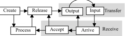
FLOWTHING MACHINE MODELThe Flowthing Machine (FM) model is a diagrammatic language for representing “things that flow,” called flowthings. Flow in FM refers to exclusive (i.e., being in one and only one) transformation among five states (also called stages): creation, release, transfer, receive, and process, as shown in Figure 1. A flowthing can be called simply a thing.
[image:3.612.320.521.619.678.2]The fundamental elements of FM are described as follows:
Figure 1. Flow system (machine) Receive
Transfer Release
Process Accept Arrive
Output Input
939
Flowthing: A thing that has the capability of being created, released, transferred, received and processed while flowing within and between flow systems. The conception of a thing in FM is very general. For example, according to Katsiri [19], “Events form an apparently distinct kind, different from things like people, planets and books.” Nevertheless, from the FM point of view, an event is a flowthing; e.g., it can be created and processed.
Flow system: A flow system is a context of flow that comprises the characteristic five stages and the connections among them. It provides a building block for the things and activities performed on them.
Spheres and subspheres are the environments (contexts) of the flowthing and reflect the structure
of its flow. A sphere is a context of flow, not necessarily a flow system, but its context, a container or bounded space of flow. It provides a framework supporting the flow at different levels, and also a background picture, situating things and flows [these terms are inspired by FaberLeón-Araúz [54]). Flow of a thing does not exist outside the basic sphere (context) of its flow system (Figure 1) that embodies the flow that carries things. Flow is a product of conceptual movement among stages of creation, release, transfer, receive, and process in contextual spheres, analogous to the flow of the Mississippi River through the contexts of specific cities within specific counties in specific states within the United States. Spheres restrict the “space” within which a flow of things can be specified.
Triggering: Triggering in FM is the activation of a flow, denoted by a dashed arrow. It is a dependency among flows and parts of flows.
Example: According to Iqbal [42], real-time embedded systems work within environments comprising components interacting with each other and often bound by time constraints. “There are a few approaches reported in the literature for the environment modeling of embedded systems.”
Context means, that an entity is … embedded in an environment… the context is a description of the environment and a dynamic grouping mechanism that encloses all entities, which are concerned by the context… The context changes or influences the relation between entities. … [5].
Choi et al. [46] use annotated UML diagrams as the method for modeling embedded systems based on requirements specification. They utilize a use
case diagram to elicit requirements, a class diagram to specify the structure of the system, and a sequence diagram with timing constraints to specify the behavior of the system. They synthesize state
machines from sequence diagrams for the purpose
of simulation.
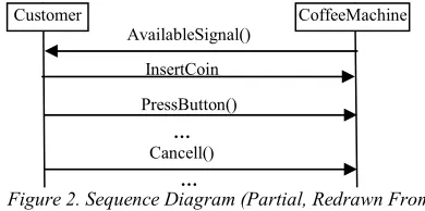
As an example, Choi et al. [46] provide a sequence diagram that specifies the behavior of a coffee machine, shown partially in Figure 2. The diagram maps five states of the machine: Initial availability signal, after coins are inserted coins, after coffee button is pressed, Cancel, and Coffee.
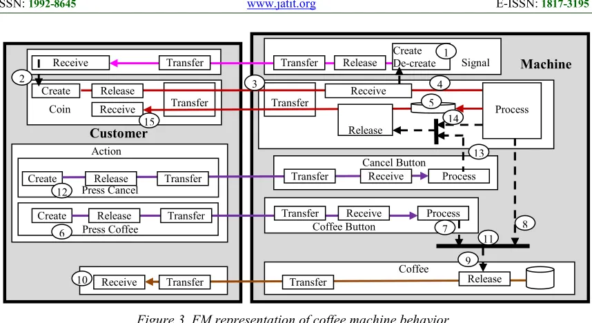
Figure 3 shows the same problem specified in FM as follows: at circle 1, the machine creates availability signals that flow to the customer. Receiving the signal triggers the customer to insert coins (2; here “create” indicates the introduction of coins) that flow to the machine (3). The machine receives the coins (hence, shuts off the availability signal), then processes them in some way (4) before storing (5). If the customer presses (6) the Coffee button, the action flows to the machine and, along with the previously inserted coins, triggers (8) a flow of coffee (9) to the customer (10). The thick horizontal line (11) indicates satisfying both conditions: receiving coins and coffee button is pressed. This line is used for simplicity; however, it can be replaced with FM notation.
Alternatively, if the customer presses the Cancel button (12), the action is received by the machine and triggers (13) a flow of coins back to the customer from storage (14, 15).
Choi et al. [46] synthesize state machines from sequence diagrams, but the FM representation reveals many additional states, e.g., coins in state of being transferred (helpful for determining the cause of malfunction), or machine in a state of receiving
or processing coins or releasing (extracting the
coffee from storage) or transferring coffee to a customer. However, if our interest is in only the five states mentioned by Choi et al. [46], Figure 4 shows the boundaries of these states. Note the way contextual inputs/outputs are represented in the diagram.
AvailableSignal()
InsertCoin
PressButton()
Customer CoffeeMachine
…
[image:4.612.320.515.239.336.2]…
Figure 2. Sequence Diagram (Partial, Redrawn From [46])
940 The state diagram used by Choi et al. [46] in their simulation can be easily abstracted from the FM representation (see Figure 5). Further study could clarify the possibility of using FM methodology in such a field.
Here it is sufficient to claim that the FM diagram is a richer and more complete representation than the UML sequence and state diagrams for mapping this example of the coffee machine.
4.
CONTEXT-AWARE PROCESSES:CHANGES
[image:5.612.98.527.76.310.2]This section demonstrates that FM provides a new conceptualization of the context of processes that can be used as a frame of reference in the development of modeling techniques. This utility can be demonstrated by using FM to re-model two examples from the literature that aim at “a conceptual integration of context with process models … so as to be able to derive a procedure for identifying context relevant to a given process” [3].
Figure 5. States diagram extracted from Figure 4
S5
S2 Receiving coins
S3
Coffee button
S4
Coffee S1
Signaling
Cancel
[image:5.612.96.530.324.492.2]
Coin
Figure 4. FM representation of the five states
Coin
Coffee Button
Process
Transfer Receive
Transfer Coffee Release
Signal
Receive Process
De-create
Transfer
Transfer Release Create Signal
Cancel Button Process
Transfer Receive
[image:5.612.94.304.607.679.2]Release Transfer
Figure 3. FM representation of coffee machine behavior
Transfer
Transf
Receiv
SignalCreate
Create Coin
Press Coffee Coffee Button
Process
Receive Press Cancel Create
Cancel Button
Transfer Coffee Release
Process
Release Transfer Transfer Receive
Transfer Receive
Release Transfer
Transfer Receive
Receive
Receive Transfer Transfer Release
Transfer Release
Process Release
Action
Machine
Customer
2 3 4
5
6 7 8
9
10
11 12
13 14 15
941
4.1 Changes In Weather Conditions
According to Rosemann et al. [3], published work in software systems deals with the notion of change only after requirements have already been identified and evaluated. Therefore, modeling techniques capture only the reactive part of a process and lack contextualization, i.e., the stimuli for change. Traditionally, one way to handle changes is to include contextual variables in the control flow, such as production rules, e.g., “if, then.” This leads to “unnecessary model extensions, mixes individual run-time with build-time decisions” [3]. Another method is to design multiple process models for different scenarios and then highlight deviations within these models. “The shortcoming of this approach is the high degree of redundancy between the models” [3].
Consider the scenario provided by Rosemann et al. [3] of context-aware processes that must change depending on weather conditions during storm season (October-March). The process is designed to handle inbound phone calls from customers with insurance claims and is supported by operation of a call center. While this process runs smoothly most of the year, the organization faces a dramatic increase in incoming calls during storm season. In order to cope with this increase in call traffic, the insurance company operates an event-based response system that differentiates calls into categories. Response strategies are defined for each category, utilizing additional external resources together with changes in the procedure by which claims are lodged. Additional resources are utilized by hiring of casual staff whose performance in call handling time is lower than the performance of the professional call center agents. Second, a streamlined way of lodging claims is applied in order to reduce average call handling time as well as waiting time in the queue in a “rapid lodgment of claims” process.
Figure 6 shows a partial view of the contextual variable of weather that impacts control flow and the involved organizational resources. In FM, the context (sphere) is integrated into the representation of the system. As a context diagram, it can be a useful starting point for designing a system and allows stepping back to examine the big picture of the system landscape. The focus is on things rather than on technologies, protocols, and other low-level details [33].
Figure 7 shows the FM representation of Rosemann et al.’s [3] context-aware situation. The
event (circle 1) of April-September (see Figure 8a)
starts (2; is naturally created) and takes its course (processes), hence triggering (3) activation of the April-September system (4, enclosed in green in online version). The event (clock) in the time
context that “awakens” the April-September system can be implemented in different ways that would also deactivate the October-March system. Accordingly, the created claims (5) flow (6) to the agent to be processed (7) and trigger registration (8). Similarly, the October-March event (9) activates its system (10; enclosed in blue in the online version). See Figure 8b.
Accordingly, claims (5) flow to the agent (6) or to the novice agent (11). The distribution mechanism is an internal detail of the transfer stage of claims. The agent’s claims as well as those of the novice agent flow (12-14) to the “Rapid lodgment” sphere (15), where the claims are processed (16) to trigger creation of a registration (17).
[image:6.612.107.538.584.719.2]The contrast between Figure 6 and 7 needs little elaboration. Weather as context has been integrated into the FM representation as a sphere of time with a flow system of events. There is no doubt that FM provides a new way to model context-aware systems.
Figure 6. Weather as a contextual variable that affects control flow (partial, redrawn from [3]) Phone call
received
Sufficient information is not available Sufficient information is
available
Call centeragent Check if sufficient
information is available Call centeragent
(novice)
X
Phone call received
Sufficient information is not available Sufficient information is
available
Call centeragent Check if sufficient
information is available
X
Call center Brisbane (April – September) Call center Brisbane (October– March)
942
4.2 Changes In Business Environments
Rosemann et al. [3] describe a major airline’s ticket reservation and check-in process, where user completes an online form to draft an itinerary. After confirmation and electronic payment, an eTicket is issued, allowing travelers to check-in at the airport using photo identification and to check-in and select available seats over the Internet.
Normally, traditional ticket counters are also available for check-in. Independent of the check-in option selected, at some stage a traveler is required to undergo safety checks before boarding the aircraft. Figure 9 shows Rosemann et al.’s [3] process model.
Figure 7. FM Representation Of The Weather As A Contextual Variable That Affects Control Flow
April-September system (Green)
5
Claim
Novice agent
Transfer
Receive Release
11
Process Create Rapid lodgment
Process
15
16
Transfer Release Process
13
Transfer Receive Registration Create
14
Create Transfer
Release Receive
Transfer Process
7 17
Agent
8
Create Create Process
October-March system (Blue)
10 4
Process
Create: October-March Process 1 Events Create: April-September Process
2 3
12 6
9
(a) (b)
Figure 8. The Two Overlapping Functional Systems Shown In Figure 7
Claim
Novice gent Transfer
Receive Release Process
Create Rapid
Process
Transfe ReleasProcess Transfer
Receive
Registration Create
Create
Transfer
Release
Receive Transfer Process Agent
Claim
Novice gent Transfer
Receive
Release Process Create Rapid lodgment
Process
Transfer Release Process Transfer
Receive
Registration Create
Create
Transfer
Release
Receive
943
Figure 10 shows its corresponding FM representation.
Ticket reservation and check-in processes run smoothly in regular business environments; however, system failures and other circumstances can lead to a greater number of traditional check-ins than expected. Contextual variables include the availability of an Internet connection. An internal server crash would affect the availability of an Internet connection and occur within the internal context, since it is related to the application system and networking infrastructure of the airline company. “By examining the chain of events that necessitates changes in the process, reactions can be anticipated based on observations in the early stages of the chain, i.e., at best in the environmental context” [3].
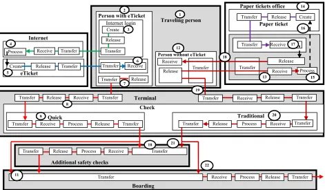
In Figure 10, the FM representation of the ticket reservation and check-in process, two types of traveling persons are differentiated (1):
(i) Person with eTicket (2): Logs into the system (3) through the Internet to be processed (4) and receive an eTicket (5-6). The person then physically (7) goes to the terminal (8) to be quickly checked in (9). By assumption, the traveler has his or her own eTicket and may go through additional safety checks (10) or straight to boarding (11).
Need for travel occurs
Purchase eTicket
X
Regular ticket reservation and check-in process
…
Check, if Internet is available
Internet is Available
Internet is not Available
eTicket Check-in
system Purchase
Paper Ticket
X
Quick check-in Terminal available
Quick check-in is not Terminal available
Figure 9. Airline Process Model With Context Consideration (Partial, Redrawn From [3])
…
Figure 10. FM Representation Of The Airline Process Model With Context Consideration
Create
Internet
eTicket
Paper tickets office
Paper ticket
Process
Terminal
Create
Transfer
Traveling person
Create
Process Receive Transfer Transfer
Receive
Release Transfer
Transfer
Transfer Receive
Release
Release Receive
Release Transfer Transfer
Receive
Check
Quick Traditional
Internet login
Transfer Release
Transfer
Transfer Release Receive Transfer
Transfer
Transfer Receive Process Release Transfer Release Process Receive
Receive Release
Person with eTicket
Person without eTicket
Additional safety checks
Transfer Transfer
Process Transfer
Receive Release
Transfer
Boarding
Process Receive
Release
Release
Transfer
1 2
3
5 4
6
7
8
9
10
11
14
13 12
15 16
17
18
19
20
21
22
944 (ii) Person without eTicket (12) goes physically
(13) to an office where paper tickets are issued (14), where the traveler is processed (15) to be issued a ticket (16). The traveler then returns from the ticket office (18) and enters the terminal (19) to go through the traditional check-in process (20). He or she may go through additional safety checks (21) or straight to boarding (22).
The FM description is a map of all possible processes that could be affected by context events
such as an internal server crash that would affect the availability of an Internet connection. Figure 11 shows four possible changes in the system of the airline:
(a) Internet is down, with additional safety check (b) Internet is down, no additional safety check (c) Tickets available only through the Internet, with additional safety check
(d)Tickets available only through the Internet, no additional safety check
5.
CONCLUSIONThis paper introduces a flow-based diagrammatic language as a new diagrammatic modeling foundation for context-aware systems. A context is viewed as a sphere (container) in a system of flows that affects what flows are permitted or blocked.
Figure 11. Four Different Possible Events That Would Change The Airline Process
Creat Interne t eTicket
Paper tickets office
Paper ticket Process Terminal Create Transfer Travelling person Create
Proces Recei Transf Transfe
Recei
Release Transfer Transfer
Transfer Receive
Release
Release
Receive
Release Transf Trans
Receive Check Quick Traditio nal Internet Transf Relea Transfe
Transfe Releas Receiv Transfer
Transfe
Transfe Receiv Process Releas Transfe
r Transfer Release Process Receive
Receive Release Person with eTicket
Person without eTicket
Additional safety checks Transfer Transfe Process Transfer Receive Release Transfer Boarding Process Receiv Releas Releas Transfer
Creat Interne t eTicket
Paper tickets office
Paper ticket Process Terminal Create Transfer Travelling person Create
Proces Recei Transf Transfe
Recei
Release Transfer Transfer
Transfer Receive Release
Release
Receive
Release Transf Trans
Receive Check Quick Traditio nal Internet Transf Relea Transfe
Transfe Releas Receiv Transfer
Transfe
Transfe Receiv Process Releas Transfe
r Transfer Release Process Receive
Receive Release Person with eTicket
Person without eTicket
Additional safety checks Transfer Transfe Process Transfer Receive Release Transfer Boarding Process Receiv Releas Releas Transfer
(b) Internet is down, no additional safety check (a) Internet is down, with additional safety check
(d) Tickets only through the Internet, with no additional safety check
945
The paper takes the approach of redesigning examples from context-aware systems in the proposed diagrammatic modeling language. These diagrams seem to have a potential role to play in the design of context-aware systems, and they could be used to integrate context into a system’s high-level specification, including the modeling of context events such as weather changes and server crashes discussed in section IV that would affect the work of the system.
It may be claimed that FM produces complex diagrams. The interesting aspect of FM description is the systematic application of the five stages of flow. This application creates more complete specifications; however, it is possible to simplify and customize the depiction by reducing the level of description. In FM, if we are interested in lumping together the details (i.e., internal structures of spheres), we can erase all stages and unify all types of flow in the model. FM brings internal details up to the conceptual level for analysis; however, FM details are also suitable descriptions for bridging the gap between IT expert and user, analogous to detailed construction drawings understood by owners as well as by engineers.
FM has been utilized in the design of several context-aware systems including social networks [47] Hardware [48] and Health [49] systems. The outcome of this new approach will form the foundation for further research and exploration of applications in more complex systems with context-related changes.
REFERENCES:
[1] Soffer, P. (2005). Scope analysis: Identifying the impact of changes in business process models. Software Process: Improvement and
Practice, vol. 10, n. 4, pp. 393-402.
[2] Regev, G., Bider, I., Wegmann, A. (2007). Defining business process flexibility with the help of invariants. Software Process:
Improvement and Practice, vol. 12, n. 1), pp.
65-79.
[3] Rosemann, M., Recker, J. C., C. Flender, (2008). Contextualisation of business processes. International Journal of Business
Process Integration and Management, vol. 3,
n. 1, pp. 47-60.
[4] Chambers Thesaurus, New Edition (W & R
Chambers, 1991). ISBN: 0-550-10572-7 [5] Bauer, J. (2003). Identification and Modeling
of Contexts for Different Information Scenarios
in Air Traffic, Thesis, Technical University of
Berlin, Mar.
[6] Dey, A. K., Abowd, G. D. (2000). Towards a Better Understanding of Context and
Context-Awareness. CHI 2000 Workshop on the What,
Who, Where, When, and How of Context-Awareness, 2000.
[7] Kamberov, R., Santos, V., Granell, C. (2016).
Toward Social Paradigms for Mobile
Context-aware Computing in Smart Cities, 11th Iberian
Conference on Information Systems and Technologies (CISTI).
[8] Prekop, P., M. Burnett, M. (2003). Activities, context and ubiquitous computing. In
Computer Communications, vol. 26, pp.
1168-1176.
[9] Gustavsen, R. M. (2002). Condor: An Application Framework for Mobility-based
Context-aware Applications, Proceedings of
the Workshop on Concepts and Models for Ubiquitous Computing,.
[10] Hofer, T., W. Schwinger, M. Pichler, et al. (2003). Context-Awareness on Mobile Devices:
The Hydrogen Approach, Proceedings of the
36th Annual Hawaii International Conference on System Sciences, vol. 10.
[11] Schilit, B., Adams, N., R. Want, R. (1994)
Context-Aware Computing Applications,
Proceedings of the Workshop on Mobile Computing Systems and Applications, pp. 85-90.
[12] Chen, G., Kotz, D. (2000). A Survey of Context-Aware Mobile Computing Research. Technical Report TR2000-381. Dept. of Computer Science, Dartmouth College, Hanover, NH.
[13] Dadu, M. (2015). Context awareness,
LinkedIn SlideShare, Dec 14.
http://www.slideshare.net/mohitdadu1/context-awareness
[14] Brown, P. (1997). J.D.X. Chen, Context-aware applications: from the laboratory to the marketplace. IEEE, vol. 4, pp. 58-64.
[15] Abowd, G. D., Dey A. K., Brown P. J., Davies, N., Smith, M., Steggles, P. (1999)
Towards a Better Understanding of Context
and Context-Awareness, Proceedings of the
First International Symposium on Handheld and Ubiquitous Computing, ser. HUC ’99. (London: Springer-Verlag, 304–307).
[16] Strang, T., Linnhoff-Popien, C. (2004). A
Context Modeling Survey, Workshop on
946 [17] Bettini, C., Brdiczka, O., Henricksen, K.,
Indulska, J., Nicklas, D., (2010). Ranganathan A., Riboni, D. A. (2010). A survey of context modelling and reasoning techniques, Pervasive
and Mobile Computing, vol. 6, pp. 161–180,
April.
[18] Perera, C., Zaslavsky, A., Christen, P., Georgakopoulos, D. (2014). Context aware computing for the Internet of Things: A survey,
IEEE Communications Surveys & Tutorials,
vol. 16, n. 1, pp. 414-454.
[19] Katsiri, E. (2005). Middleware Support for Context-Awareness in Distributed
Sensor-Driven Systems, Technical report (Ph.D.
Thesis), University of Cambridge Computer Laboratory, February.
[20]Schmidt, A. (2002). Ubiquitous Computing:
Computing in Context. Ph.D. thesis, Lancaster
University, UK.
[21] Alshahrany, F., Abbod, M., Alshahrani, J., Alshahrani, A. (2016). Intelligent Networks Data Fusion Web-based Services for Ad-hoc Integrated WSNs-RFID, International Journal
of Engineering and Technology Innovation,
vol. 6, n. 1, pp. 1-15.
[22] Chen, Y., Liu, Z., Vainio, J. (2013).
Activity-Based Context-Aware Model, Second
International Conference, DUXU 2013, Las Vegas, USA,.
[23] Henricksen, K., Indulska, J. (2003). A Framework for Context-Aware Pervasive
Computing Applications, School of
Information Technology and Electrical Engineering, University of Queensland, September.
[24] Dey, A. K. (2000). Providing Architectural
Support for Building Context Aware
Applications, Ph.D. thesis, Georgia Institute of
Technology, November.
[25] Al-Fedaghi, S. (2011). Developing Web Applications, International Journal of
Software Engineering and Its Applications,
vol. 5, n. 2, pp. 57-68.
[26] Al-Fedaghi, S. (2011). Conceptual Foundation for Specifying Processes, International Journal
of Advancements in Computing Technology,
vol. 3, n. 4, pp. 265-278.
[27] Al-Fedaghi, S. (2015). Heraclitean Ontology for Specifying Systems, International Review
on Computers and Software, vol. 10, n. 6.
[28] Al-Fedaghi, S. (2006). Personal Information
Flow Model for P3P, W3C Workshop on
Languages for Privacy Policy Negotiation and Semantics-Driven Enforcement, Ispra, Italy.
[29] Al-Fedaghi S., Al-Saqa, A. (2013). Toward A Conceptual Base for Protocol Engineering,
Journal of Theoretical and Applied
Information Technology, Vol. 51, No. 2, May.
[30] Al-Fedaghi, S. (2012). Conceptual Framework for Recursion in Computer Programming,
Journal of Theoretical and Applied
Information Technology, Vol. 46 No. 2.
[31] Balavalad, K., Manvi, S., Sutagundar, A. (2009). Context Aware Computing in Wireless
Sensor Networks, Advances in Recent
Technologies in Communication and
Computing, ARTCom09,International
Conference, pp. 514-516, 2009.
[32] Alanazi, H. O., Alnaqeib, R., Hmood, A. K., Zaidan, M. A., Al‐Nabhani, Y. (2010). On the Module of Internet Banking System, Journal of
Computing, vol. 2, n. 5, May, ISSN 2151-9617.
[33] Software Architecture for Developers, Software architecture and the C4 model.
leanpub.com, accessed Oct. 2016.
http://www.google.com.kw/url?sa=t&rct=j&q= &esrc=s&source=web&cd=4&cad=rja&uact=8 &ved=0ahUKEwj3iaHOnObPAhWGVhQKH UlYDu0QFggvMAM&url=http%3A%2F%2Fd emo.ckan.org%2Fdataset%2Fb007f3c5-6bb4-
416b-b5f4- a189baac363a%2Fresource%2F1de316ca-
9359-43cd-ab18- e20cb177e58e%2Fdownload%2Fc4-model-
cheat-sheet.pdf&usg=AFQjCNF_JxTdsafAsGUQism iNuE-lMPd0w
[34] Sagaya Priya, Kalpana, K. S., Y. (2016). A Review on Context Modelling Techniques in Context Aware Computing, International Journal of Engineering and Technology
(IJET), vol. 8, n. 1, pp. 429-433, 2016. p-ISSN
: 2319-8613
[35] Gomaa, H. (2011). Towards Integrated System
and Software Modeling for Embedded Systems,
International Workshop on Model-Based Systems Engineering (ACES11), MODELS Conference, Wellington, New Zealand, October.
[36] Acretoaie, V. (2016). Tutorial: System
structure modeling using MagicDraw,
Technical University of Denmark, accessed Oct.
947 w.pdf&usg=AFQjCNHYEXHDEhQqr7JaM0v ofQt-kPYPnQ
[37] Niu, X., Wang, Z. (2016). A Smart Home Context-aware Model Based on UML and Colored Petri Net, International Journal of
Smart Home, vol. 10, n. 1, pp. 101-114, 2016.
[38] Han, S., Youn, H. Y. (2012). Petri net-based context modeling for context-aware systems,
Artificial Intelligence Review, vol. 37, n. 1, pp.
43-67.
[39] Haiouni, H., Maamri, R. (2014). Context-aware automatic service selection mechanism for ambient intelligent environments, Ambient
Intelligence: Software and Applications, 291
(Springer International, pp. 1-11).
[40] Chen, H., Finin, T., Joshi, A. et al., (2005).
Using OWL in a Pervasive Computing Broker.
Defense Technical Information Center, 2005. [41] Pathan, K. Ta. (2013). Activity Awareness in
Context-aware Systems using Software
Sensors, Ph.D. Thesis, Department of
Computer Science, University of Leicester, October.
[42] Iqbal, M. Z. Z. (2012). Environment
Model-based System Testing of Real-Time Embedded
Systems, Ph.D. Thesis, Department of
Informatics, Faculty of Mathematics and Natural Sciences, University of Oslo, September.
[43] Hong, J.-Y., Suh, E.-H., Kim, S.-J. (2009) Context-aware systems: a literature review and classification, Expert Systems with
Applications, vol. 36, pp. 8509-8522.
[44] Park, H.-S., Cho, S.-B. (2012). A modular design of Bayesian networks using expert knowledge: context-aware home service robot.
Expert Systems and Applications, vol. 39, pp.
2629-2642.
http://dx.doi.org/10.1016/j.eswa.2011.08.118 [45] Faber, P., León-Araúz, P. (2016). Specialized
knowledge representation and the
parameterization of context, Frontiers in Psychology.
http://dx.doi.org/10.3389/fpsyg.2016.00196. [46] Choi, K. S., Jung, S. C., Kim, H. J., Bae, D.
H., Lee, D. H. (2006). UML-based Modeling and Simulation Method for Mission-Critical
Real-Time Embedded System Development,
IASTED International Conference
Proceedings.
[47]Al-Fedaghi S. and AlMeshari, H. (2015). Social Networks in which Users are not Small Circles, Informing Science, Vol. 18, 205-224.
[48]Al-Fedaghi S. and Aljallal, N. (2014). Conceptual Schematization of Microcontroller and Assembly Language, International Journal
of Software Engineering and Its Applications,
Vol. 8, No. 10, pp. 179-190.
[49]Al-Fedaghi, S. (2014). Design principles in health information technology: An alternative to UML use case methodology, International Journal of Healthcare Information Systems
and Informatics (IJHISI), Vol. 9, No. 1, pp.
30-41.
![Figure 6. Weather as a contextual variable that affects control flow (partial, redrawn from [3])](https://thumb-us.123doks.com/thumbv2/123dok_us/8907635.957579/6.612.107.538.584.719/figure-weather-contextual-variable-affects-control-partial-redrawn.webp)