195
TRACKING VEHICLES IN URBAN SMART CITY BASED
XILINX PLATFORM
1INAAM RIKAN HASSAN, 2MOHAMMED ABDULRAHEEM FADHEL
1, 2University of Information Technology and Communications, Baghdad, Iraq
E-mail: 1[email protected], 2[email protected]
ABSTRACT
Computer vision becomes one of the significant smart city applications due to the unbelievable growth in electronics, informatics, and communication fields. Since the smart city is directed by smart self-governing systems, A lot of algorithms have been released for achieving smart city requirements. These algorithms include methods for detecting text, faces, vehicles and moving objects. Then, by comparing their output with the ground-truth, the performance of these algorithms can be measured. This paper focusing on following (detect and track) the moving vehicles. Two different object detection algorithms have been tested, namely temporal difference algorithm and fixed background algorithm for a video of (120 x 160) pixels frame-size. The designed system was implemented based on FPGA board (Xilinx-ISE 14.6 XC3S700A), while the simulation was built by employing MATLAB. To stay away from the limitation of the FPGA board size, the Verilog code was invoked by utilizing the MATLAB platform.
Keywords: UrbanSmart City, Temporal Difference Algorithm, Fixed Background Algorithm, Xilinx
1. INTRODUCTION
The development of a smart city, through the utilization of smart autonomous systems, has been expanded due to the recent growth in electronics, informatics, and communication equipments [1]. And computer vision becomes one of the significant smart city applications used in a vast scope of disciplines, extending from robotics to human computer interaction [2]. Avoiding any malfunction in the smart city systems, they must have an excessive flexibility and reliability in all circumstances [3]. Moreover, the current challenges are to upgrade the automatic systems that need small storage capacity and short processing time. Also, they do not need any task-specific thresholds or tunning process. These challenges emphasize the significance of the algorithms which are; operator-, threshold-, and task-independent, computationally efficient, and able to detect and track activities in the place of surveillance [4]. Therefore, the automated video surveillance is a significant application of the smart city systems. Now-a-day, it is commonly employed in the instantaneous traffic monitoring. More specifically, it tracks vehicles, synthesizes traffic flow, and detects the accidents through the watching cameras [5],[6].
However, the above requirements
concentrate on the process of motion estimation.
This process analyzes the consecutive frames of a video stream to recognize the moving objects [7]. The key aim of the image tracking algorithm is to execute quick and consistent similarity of an identified object, from one frame to the next one through the utilization of the image analysis methods [8]. It recognizes the dissimilar pixels with that of the background and identifies them as elements of a new real object in the foreground view [8],[9]. Hence, to get better detection-quality and to reduce the number of mis-detections, a well- modernized background model must be employed [10].
2. LITERATURE REVIEW
Due to the increased demand of vision-machine applications based on the up-to-date generation of electronic systems derived from camera platform, a variety of techniques related to moving object tracking have been presented in the latest years.
Ling et al. [11] introduces a multi-object detection and tracking model based on stereo vision to be used in surveillance systems. His model
overcomes the object occlusion, shadow
196 Su Liu [12] implemented a reconfigurable hardware using a parallel architecture as an object tracking system. His algorithm is based on the background subtraction. Also, the dual object region search technique is further proposed to boost the system performance under complex tracking
conditions. An Altera Stratix III
EP3SL340H1152C2 FPGA board was used for the execution.
Changiun [13] is concerned with a system for detection and tracking the motion of the objects watched by a stationary camera. This system depends on a background model based on Bayes theorem, a border tracker based on the gradient vector flow (GVF)-snake, and a Kalman estimator. The background model is utilized to spilt the foreground objects from the background. it has the ability of adaptive choice of layer number compared with Gaussian Mixture Model (GMM) background model and the benefits of insensitiveness to the original surveillances.
Alexander [14] addressed a consistent tracking of approaching traffic at urban intersections from a dynamic stage with a vision stereo system. Both depth and motion information are joined to assess the pose and motion factors of an approaching vehicle, involving the yaw rate, by method of Kalman filtering. He proposed a multi-filter real-time method to track the vehicle at intersections, since, a single-filter method be not able to envelop the dynamic scope of a vehicle adequately.
Bhavana [15] identified and tracked a moving object within a video sequence by using optical flows among video frames in contrast to image background-based detection. The optical flow method is straightforward and he implemented his project by using MATLAB simulation on Simulink.
Bastian et al. [16] have presented a multi-object tracking after multi-object detection algorithm. Their approach was formulated in a Minimum Description Length hypothesis selection framework. It allows the algorithm to retrieve from dissimilarities and momentarily missing track. The object detector performs multi-view/multi-category object recognition to recognize vehicles and walkers in the input images. The detected two-dimension objects are transformed to three-dimension surveillances, which are collected in the world coordinate frame. The module of the trajectory estimation investigates the resultant three-dimension surveillances to determine actual
reasonable space-time trajectories. The Tracking process is attained by executing model selection after every frame. At any instance, they supposed that two objects will not describe the same image pixels nor reside in the same actual place.
Plamen [8] has presented two approaches
to detect and track objects in video streams. A Cauchy type of kernel is employed in a recursive density estimation (RDE) for visual detection (as opposite to the regularly utilized Gaussian one), is proposed. This approach evolves Takagi-Sugeno (eTS) neuro-fuzzy system to track the detected object detected. For background subtraction, the proposed approach is considerably faster than the familiar kernel density estimation (KDE) approach.
Hamid et al. [17] have presented a design for several graph-based algorithms that utilize the relationship between the locations of the tracked moving vehicles. An investigating assessment of the video streams that accumulated from dissimilar conditions and cities, plus the simulated traffic data, which was produced to examine the factors’ effects such as congestion.
Julius [18] has proposed a functional assessment metric for the algorithms of tracking. The metric is labeled “Label and Size Based Evaluation Measure” (LSBEM). It utilizes the single assigned label to the objects and to the size of the detected objects by the algorithm of tracking as the major issues for assessing it.
An approach to detect and track the moving
vehicles in a conventional parking batch was applied by Parameswaran [19]. The approach includes an adaptive real-time background subtraction and shadow removal followed by a set of morphological functions so as to improve the foreground mask. This mask is subsequently employed to draw a distinct bounding box over the moving vehicles in the primary video order. The output video order is the primary order with a bounding mask involved about the moving vehicles.
3. MATERIAL
3.1 Concurrent Target Detection
197 characteristic [9]. In general, there are three types of video segmentation algorithms which are:
a. Edge information: This type uses initially a
canny edge detector to determine the edge information of every frame, and next, stay tracking these edges. Also, a filter of morphology motion is operated to determine the edges of the foreground and background objects. Finally, a filling method is used to link these edge information to create the last object masks. Moving and stationary camera situations can be applied by this type of algorithms. Unfortunately, the computation time is extremely high.
b. Image segmentation: In this type of
segmentation algorithms, such as color segmentation and watershed transform, the first stage is to divide each frame into numerous identical areas. Then, motion information are combined with a frame difference, optical flow, or motion estimation. As a result, areas with motion vectors dissimilar with the global motion areas are merged together as foreground areas. This type almost gives segmentation results with accurate boundaries. Again, the computation time is extremely high and the merging process almost has numerous variables to set.
.
c. Change detection: Initially, the change
detection mask is formed based on the frame difference (after setting a threshold). The segmentation results undergo from noise, light varying, shadow, discovered background situations, and unmoving object situations. The robustness can be achieved through numerous post-processing algorithms. Note that complex post-processing may decay the computational competence. Also, the change detection threshold is enormously unstable and cannot be set automatically. Therefore, this type is not practicable for real-time applications.
3.2 Background Subtraction (BS)
There are two types of background subtraction; non adaptive BS, and adaptive BS. In the nonadaptive background subtraction approach, the background is assumed to be stationary and is modeled in terms of a set of four parameters. The
first two parameters are the expected color value
vector, Eij and the variancematrix, Cij: Eij = E { xij[n] }: 1 ≤ n ≤ N
Cij = I [(𝜎 )2 𝜎 2 𝜎 )2]T
where E {.} is the expectation operator, xij is the
pixel value at (i, j) position, n is the current frame
number, N is the number frames with no moving
objects, and σ is the standard deviation of the three
color bands (R, G, B). The other two parameters
denote the brightness and the color distortions of
each pixel from the corresponding mean value [19].
In adaptive BS, the four parameters of the
background model computed earlier are updated by using the following equations:
𝐸 𝑛 1 𝛾 𝐸 𝑛 1 𝛾 𝑋 𝑛
𝐶 𝑛 1 𝛾 𝐶 𝑛 1 𝛾 𝐺 𝐺
where, 𝐺 𝑋 𝑛 𝐸 𝑛 , and 𝛾 is a control
parameter known as the learning rate of adaptation,
𝛾 ≈ 5*10-6 [42].
To summarize the procedure so far, assume
the initial background model as a seed and then
compute the αij [n] and λij [n] values for each input
frame. Then normalize αij [n] and λij [n] as:
𝛼 𝑛 𝜆 𝑛
Finally, the pixel mask Mij(n) can be
classified according the rule
𝑀 𝑛 𝐵𝑎𝑐𝑘𝑔𝑟𝑜𝑢𝑛𝑑 ∶ 𝑜𝑡ℎ𝑒𝑟𝑤𝑖𝑠𝑒 𝐹𝑜𝑟𝑒𝑔𝑟𝑜𝑢𝑛𝑑 ∶ 𝛼 𝑛 𝜏
3.3 Foreground Extraction
To adaptively extract the foreground, a mean value of the smallest distance between the current image and the background model is taken [20], according to which, the foreground is obtained through the subsequent steps. First, in each pixel, the
nearest Ck value is acquired with a new input image.
Ck is defined as the background histogram center
that has a larger probability than 1/Nr , the reciprocal
of the number of bins for each color dimension d.
Then, in each pixel and in each dimension, the
smallest distance between Ck and the new input
values is determined:
𝐷𝑖𝑠𝑡 𝑚𝑖𝑛∀ 𝐶 𝑥
where
198
Foreground can be obtained by comparing
Bd with Distd in this way:
𝑖𝑓 |𝐷𝑖𝑠𝑡 |
1 𝐺𝑟𝑎𝑑 , 𝐵 𝛾
𝑡ℎ𝑒𝑛, 𝐹 1,
𝐺𝑟𝑎𝑑, 𝐺 1 𝐺𝑟𝑎𝑑𝐺 , 𝑤𝑥|𝐷𝑖𝑠𝑡 |/𝐺
𝐸𝑙𝑠𝑒, 𝐹 0,
𝐺𝑟𝑎𝑑, 𝐺 1 𝐺𝑟𝑎𝑑𝐺 , |𝐷𝑖𝑠𝑡 |/𝐺
where:
γ is the threshold weight. The values of 1 - 1.5 can
be used
F = 1 relates to the foreground,
F = 0 relates to the background,
Gradt,,r is the average of absolute Distr at time t
w weight to control the speed of adaptation for the
environments.
If w is high, the algorithm rapidly, adjusts
to the environment, and moderate noise. But, if w is
too high, the algorithmmisjudges the foreground as
a background. w has a value of 0.1 - 0.3.
3.4 Estimating Background in Fixed Camera Videos
The adaptive codebook algorithm based background modeling can be used for stationary cameras, for greatness variations encoding at each pixel in the video frame. The codewords (boxes) are used to form a codebook. These codewords stand for ranges of greatness values, which expand to include all the greatness values happening at a certain pixel. These values may relate to foreground, background, or noise. Initially, the codebook is a very big codebook. So, it needs to refine it using a temporal filtering step through splitting the contributed codewords by the moving foreground objects from the real background codewords. The real value of the background pixel normally returns within a bounded period. It is supposed that the moving foreground contributed it and is detached from the codebook, if the codeword does not return within a bounded period. Finally, at each pixel, it is recommended to get the mean of all background classifications to develop a single stationary background [21].
3.5 Morphological Operation
Morphological operations are usually performed to remove noise and to filter out jitter objects to improve segmentation results [21]. Morphology is an approach to extract image components which are helpful in the description and interpretation of the region shape, like skeletons, boundaries, etc. For instance, the operation “opening” usually flattens the shape of an object by removing thin projections. Also, the additional supplementary pixel is detached. Morphology is expressed in terms of “set theory”. The sets stand for an object in the image. For example, in a binary image, the set of all white pixels is a whole morphological description of an image. The sets are members in the two-dimension integer space of the binary images. And each element of a set is a two-dimension vector whose coordinate is the (x, y) coordinates of a white pixel in the image. Erosion operation removes pixels on object boundaries and is used to shrink the object [7].
𝐴 ⊝ 𝐵 𝑥 ∈ 𝐸 |𝑥 𝑏 ∈ 𝐴 𝑓𝑜𝑟 𝑒𝑣𝑒𝑟𝑦 𝑏 ∈ 𝐵
Equivalently, so
𝐴 ⊝ 𝐵 ⋂ ∈ 𝐴
where A and B are two sets in EN with elements a
and b, respectively.
Then, the binary erosion of A by B is the
set of all elements x, for which x + b ∈ A, for every
b ∈ B. Closing operation expands an image and then
corrodes the expanded image utilizing the same configured element. It is utilized to remove minor holes in the contour. The closing of an image A by a configured element B, represented by A • B, is identified as [7].
𝐴 • 𝐵 𝐴⨁𝐵 ⊝ 𝐵
𝐴 • 𝐵 ⋂𝑦 𝐵 ∩ 𝐴 ∅ 𝐵
𝐴 • 𝐵 ⋃ ⊆ 𝐵
𝐵 ⊆ 𝐴 ⇔ 𝐵 ∩ 𝐴 ∅
where ⊕ and ⊖ denote either grayscale or binary
199
3.6 FPGA Employment in Object Detecting and Tracking Implementation
The FPGA is commonly utilized in image processing applications owing to its capability to deal with large quantities of receiving and leaving data, and its capability to perform many operations in parallel on data flow [22].
Xilinx-ISE 14.6 provides a special tool that
mixes between two platforms, MATLAB and the ISE 14.6(2013) platforms. To stay away from the limitation of the FPGA board size (XC3S700A), the Verilog code is invoked by utilizing the MATLAB platform. System generator is a control panel used to control the simulation parameters and utilized to invoke the code generator for net listing. Note that every Simulink model containing elements for Xilinx blocks should enclose no less than one system generator. The system generator is responsible for generating a hardware component "hwcosim" (hardware co-simulation), that calls Xilinx JTAG Co-Simulation. The “hwcosim” block lets performing a hardware co-simulation utilizing JTAG and a platform USB, i.e., during the Simulink simulation, the JTAG Co-Simulation works together with the FPGA hardware platform.
4. METHODOLOGY
4.1 Object Selection
a. Detection of any (each) moving object which
enters the camera site. Then, these detected objects are bounded with common-color boxes and given ID numbers.
b. Tracking each object, so that it cannot take a
different ID number along its path.
c. Interactive selection of an interested object,
then bounding it with a distinctive color box and showing its path.
d. Extracts the selected object's information and
sending it to the second stage (of the following or another camera site).
The blocks in Figure 1 are as follows:
Background Assignment contains
vidTrack_fixedBG_1 script this program illustrates how to detect objects (cars) in a video sequence using foreground detection based on background assignment and global image threshold using Otsu's method. This program has two parts (Segmentation
and Tracking).Tracking Data Bank It stores the
feature data (property-vector) of any object passing through a region of interest (ROI). The object
property data elements are; boundingBox, Area,
Extent, ConvexArea, MeanIntensity, EulerNumber,
[image:5.612.325.513.557.689.2]Eccentricity, AspectRatio, Perimeter, and Solidity, see Figure 1.
Figure 1: the block diagram of the tracking system
200 Figure 2:Selected-object tracking-data is displayed in
the yellow zone of the UI
4.2 Hardware Implementation
Figure 1 shows the block diagram of an important component of the proposed system, the comparator. The operation of this component can be implemented on FPGA board. Figure 3 represents the comparison function block. This hardware-implemented function compares the current (A) and reference (B) property-vectors. The comparison result is then thresholded using the input threshold
(T), corresponding to error, to decide match or
unmatched condition. The logical matching vector (E) is then returned back to MATLAB to complete the operation of object recognition.
Figure 3: The comparison function block.
5. RESULTS
All the following tests have been carried out using the sixth version of "locate" application program, on Microsoft Windows 10 Professional operating system and a computer with an Intel Core i7, 2130 MHz CPU, 6 MB L3 cache, and 8000 MB of RAM. The simulation has been carried on MATLAB , and by Xilinx-ISE 14.7, the design has been implemented on Spartan-3A XC3S700A board which offers an incomparable tool for combining between the MATLAB and the ISE 14.6 platforms. To avoid the weakness of the XC3S1400A-FPGA board size, the Verilog code of Xilinx platform is invoked by utilizing the MATLAB platform.
5.1 Video Players
Two video players have been implemented,
namely (selectplay and trackplay); they are modified copies of mplay video player by Dr. Orofino of the MathWorks. They are intended for interaction with human operator and video processing functions, and also to show resultant videos of proposed algorithms.
5.1.1 selectplay
This player operates in two modes; it displays video data on the screen and feeds the video frames to be
[image:6.612.98.290.410.502.2] [image:6.612.325.511.454.704.2]proposed in video tracking algorithm
|vidTrack_fixedBG|. Any object on the screen can be interactively selected by mouse to show its path and to be tracked in the following frames -Figure 4.
When the objects enter the first camera site, the algorithm starts tracking them; it also gives each object an ID number, bounds it with a uniform color box and assigns its tracking data to an individual data structure. No tracking data are displayed on the attached UI (user interface) before an object is selected, as shown in Figure 4-a. At the time an object is selected (Object # 2 in this case), its ID number, bounding box, and path are added as augmented data to the frame and shown in red color, see Figure 4-b. At the same time, the selected object tracking data are displayed in the yellow zone of the same UI. The object is treated this way until it leaves the camera viewing area (becomes out of the interest region) as shown in Figure 4-c.
(a)
201 (c)
Figure 4: Object selecting and tracking process.
5.2 Video Processing 5.2.1 "vidTrack" Script
Several versions of this script have been issued according to foreground/background detection technique being used. It uses temporal differencing
foreground detection technique, while
vidTrack_GMM uses "Gaussian Mixture Models" statistical method for background estimation, and vidTrack_fixedBG uses the fixed background subtraction technique. The fixed background subtraction technique is commonly utilized in motion segmentation with a fixed camera.
5.2.2 "locate" Function
This function performs all tasks relating to:
interactive the object selection, tracking moving-objects in the trackplay player figure, object recognition, and superimposing augmented data on real-time frames. This function also initiates and manages a special GUI dedicated to showing binary images of reference against current objects, as well as the property error-vector of object under test. The element values of error-vector give the human operator an exact figure about the current object similarity/difference from the reference one. Another important task of this function is to flip the input video, in left-right direction, to show the algorithm immunity against object orientation.
5.3 Performance Evaluation
A particular application package has been implemented for performance evaluation of tracking algorithms. In this package, there are many important functions, they are as follows:
5.3.1 "gndTruth" Function
Syntax: vidseqGnd = gndTruth(vidSeq, discr)
This function is the pedestal of performance evaluation operation. It is an interactive tool intended for ground-truthing video sequences; a ground-truth is what a human eye decides as object's boundaries. This function, through its GUI
(graphical user interface), enables a human operator to mark target object's boundaries; it generates a binary image sequence in which only the human selected objects can be seen as white solid boxes, and black elsewhere. The output ground-truth image sequence is used in the evaluation of moving-objects detection algorithms. In a particular case, if the video sequence to be ground-truthed is a true color single-frame, it is interpreted as three gray frames. An optional discrimination input argument (discr) can be used to avoid this ambiguity. This function assigns two arrays in the base workspace, as follows:
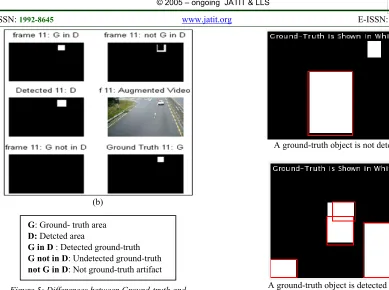
In this context, the accuracy of this
evaluation depends on the accuracy of object mapping and the relation between its ground-truth and detected-truth. Figure 5-a shows the object before entering the viewing area, and it's clear the ground-truth is not detected. In Figure 5-b, there are shadows that are interpreted by the segmentation algorithm as an added area to that of the moving object, however, in Figure 5-c some of the ground-truth is not detected because its color at this moment with light angle is the same as that of the background. Whilst, Figure 5-d shows the particular case when the detection algorithm has split a ground-truth object into two objects.
202 (b)
Figure 5: Differences between Ground-truth and detected objects.
5.3.2 "PEval-AF" Function
The name "PEval" stands for Performance Evaluation and "AF" suffix in turn stands for Average Fragmentation. This function is intended to discover cases where several output boxes cover a single ground-truth object, including overlapping and non-overlapping boxes. Input to this function consists of two variable-sets, namely the output sets of gndTruth and vidTrack_fxBG.
The function's output is a mat-file
"PEval_AF"; it comprises the following variables:
The average fragmentation of each frame,
and also the overall fragmentation which is the average of all frames' average fragmentation values, i.e. the total average fragmentation when using a particular tracking algorithm.
"fragVid", a video sequence in which a
ground box is shown in solid white color while the detected intersecting boxes are shown in red outlines. In case no detected boxes are available, no red outline is shown. Figure 6 below depicts the mentioned two cases.
A ground-truth object is not detected
[image:8.612.95.305.73.338.2]A ground-truth object is detected as two
Figure 6: Object fragmentation augmented data.
5.3.3. "PEval_ABRF_ABPF" Function
This function computes the following performance metrics:
a. ABRF: Area-Based Recall Frame; it is a metric based on pixel-count. It measures the ability of the algorithm to cover the ground-truth pixel regions. Primarily, it is calculated for each frame, which is the weighted average for the whole data set.
b. ABPF: Area-Based Precision Frame; it is a metric based on pixel-count. It measures the ability of the algorithm to minimize the false alarms. Primarily, it is calculated for each frame, which is the weighted average for the whole data set.
c. Input to this function consists of
tracking-data and ground-truth video, they are loaded automatically to function workspace as MATLAB "mat-files".
d. The function output is
"PEval_ABRF_ABPF.mat"; it comprises the following variables:
Precision variables, related to ABPF
metric, detailed above.
Ground-truth video, showing solid
white boxes that represent boundaries of ground-truth objects.
G: Ground- truth area
D: Detcted area
G in D : Detected ground-truth
G not in D: Undetected ground-truth
203
Detected video, it shows solid white
boxes of the objects' boundaries as detected by the algorithm.
5.4 Object Detection, Recognition and Tracking
Object detection is a mutual stage in every surveillance system, although every system needs diverse actions. Detection is proposed to yield the object-mask (indicated as the object-frame, as well) logical image, wherein just the object pixels are seen in white; and black somewhere else [2]. Algorithm detection’s time is the required time for splitting the background from the foreground. Frequently, it is calculated as the median of the whole video frames.
In general, the object-frame is commonly created by background model subtraction. The process is normally employed for dynamic detection in stationary events. It takes away a reference background image pixel-by-pixel from the present image (frame). Subsequently, the absolute of resulting image pixels are measured up to a threshold. The pixels are classified as foreground if their values are higher than the threshold. To lower the noise effect and to improve the detected regions, the object-frame experiences a number of
morphological functions, for example, closing,
dilation, and erosion.
Reference background model is usually created using techniques like temporal differencing in which the previous frame is considered as a background, fixed background, and Gaussian mixture models.
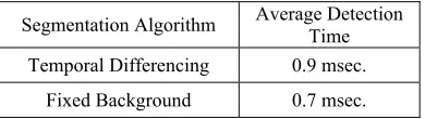
The time performance of three different
object detection algorithms has been tested, namely temporal differencing, fixed background, and Gaussian mixture models. The sample video is of (120 x 160) pixels frame-size and 120 frames; the results are shown in Table 1.
Segmentation is an extensively hard
[image:9.612.98.293.671.726.2]problem due to the usual dynamic nature of the background, such as, waving trees, shadows, and illumination variation. It requires to be perfectly managed for an effective and strong surveillance system.
Table I: Detection time of three tested algorithms.
Segmentation Algorithm Average Detection Time
Temporal Differencing 0.9 msec. Fixed Background 0.7 msec.
In the object detection process, the object
recognition is an elective stage. It recognizes the required or remarkable object, relying on its properties. More instance, object properties can be chromatic or/and morphological. These properties together are implemented in the this paper to carry out object recognition (object identification). Alternatively, the object tracking process is to establish a correlation between objects in consecutive frames and creating temporary data on the moving objects, for example, position, direction, path, and speed.
In contrast, the object level tracking
algorithm was widely utilized. In this algorithm, instead of tracking parts of objects,for example the car license plate, the total objects are tracked in each consecutive frame. In this paper, the applied technique implements the benefit of features, such as Euler number, the bounding box, mean intensity, and size. These features are obtained from the preceding parts of the system, to identify the similarity among objects in consecutive frames.
Note that, when a new object comes into in
the succeeding camera site, the algorithm starts to compare between the deliberate properties of the object with the picked up properties of the preceding camera site. If the deliberate properties error ratio of
the object is below the highest error ratio error
(0.05), then, the object is stated as a similar one and will surrounded by a red box. Also, the tracking data area is shown in red color and the object route is also illustrated in dotted red line in Figure 7 a-f. The current procedure is carrying on till the object leaves the screening area of the succeeding camera
(becomes exterior the interested area).
Subsequently, the red color will fade, as in Figure 7-g.
Finally, it should be noted that the tracking
204 (a)
(b)
(c)
(d)
(e)
(f)
[image:10.612.85.531.57.679.2](g)
Figure 7: Object detection and tracking steps
6. CONCLUSIONS
The following key points summarize the entire work:
1. The fixed background subtraction technique
is simple and commonly employed in moving object segmentation based a static camera.
2. If the value of a piece of an object gray image
is approximately equal to the background, and this piece is large enough to split into two or more pieces, then the object can be split.
3. The proposed algorithm has good immunity
against an object orientation.
4. The image dropping mean value has
205
enhanced the segmentation process
significantly.
5. The temporal differencing algorithm is the worst in object fragmentation, but it benefits from white-balance compensation (image dropping mean value). While the temporal differencing algorithm suffers from a severe deficiency, it is sensitive to object speed; it enlarges fast objects giving them a chance for splitting.
6. The fixed background algorithm has a slightly better total fragmentation ratio. In this context, the algorithm does not benefit from white-balance compensation;\ detected objects are eleven with or without compensation. This can be explained as it is not sensitive to object speed, and hence, there is no more chance for object splitting.
REFRENCES:
[1] Yazdi, Mehran, and Thierry Bouwmans, "New
trends on moving object detection in video images captured by a moving camera: A survey", Computer Science Review, Vol. 28, pp. 157-177, 2018.
[2] Zaki and Thamir Saeed, "Proposal algorithm
for Real-Time Detection and Tracking Moving Vehicles for Video Surveillance Systems Using FPGA", M.Sc. Thesis in Electrical and Electronic Eng., IRAQ, 2014.
[3] Nieto, Marcos, et al., "Vehicle tracking and
classification in challenging scenarios via slice sampling.", EURASIP Journal on Advances in Signal Processing 2011.1 (2011): 95.
[4] Das, Pritam, et al. "Measurement of
Displacement and Velocity of a Moving Object from Real Time Video." International Journal of Computer Applications 49.13 (2012).
[5] Fadhel, Mohammed Abdulraheem, Omran
Al-Shamaa, and Bahaa Husain Taher. "Real-time detection and tracking moving vehicles for
video surveillance systems using
FPGA." International Journal of Engineering & Technology 7.2.31 (2018): 117-121.
[6] Ramin Ramezani, Plamen Angelov, and
Xiaowei Zhou, "A Fast Approach to Novelty Detection in Video Streams Using Recursive Density Estimation", IEEE 4th International Conference "Intelligent Systems", 2008.
[7] Marques, Oge. Practical image and video
processing using MATLAB. John Wiley & Sons, 2011.
[8] Costa, Bruno Sielly Jales, Plamen Parvanov
Angelov, and Luiz Affonso Guedes. "Fully
unsupervised fault detection and identification based on recursive density estimation and
self-evolving cloud-based
classifier." Neurocomputing 150 (2015):
289-303.
[9] G. Prabhakar and B. Ramasubramanian, "An
Efficient Approach for Real Time Tracking of Intruder and Abandoned Object in Video Surveillance System", International Journal of Computer Applications (0975 – 8887) Volume 54– No.17, September 2012.
[10] Mubashir, Muhammad, Ling Shao, and Luke
Seed. "A survey on fall detection: Principles and approaches." Neurocomputing 100 (2013): 144-152.
[11] Ling Cai, Lei He, Yiren Xu, Yuming Zhao and
Xin Yang "Multi-object detection and tracking
by stereo vision", Elsevier, Pattern
Recognition Vol.43, pp. 4028–4041, (2010).
[12] Su Liu, Alexandros Papakonstantinou,
Hongjun Wang, Deming Chen,"Real-Time Object Tracking System on FPGAs", Shandong University, Jinan, China 2010.
[13] Changjun Wang and Guojun Dai, "Moving
Targets Detection and Tracking Based on Bayesian Foreground Segmentation and GVF -snake", Third International Workshop on Advanced Computational Intelligence - Suzhou, Jiangsu, China, August 25-27,2010.
[14] Alexander Barth and Uwe Franke, "Tracking
Oncoming and Turning Vehicles at
Intersections", University of Bonn, Germany, Institute of Geodesy and Geoinformation, 2010.
[15] Wang, Naiyan, and Dit-Yan Yeung. "Learning
a deep compact image representation for visual tracking." Advances in neural information processing systems. 2013.
[16] Scheidegger, Samuel, et al. "Mono-Camera 3D
Multi-Object Tracking Using Deep Learning Detections and PMBM Filtering." arXiv preprint arXiv:1802.09975 (2018).
[17] Murugan, A. Senthil, et al. "A study on various
methods used for video summarization and moving object detection for video surveillance
applications", Multimedia Tools and
Applications, (2018): 1-18.
[18] Julius Popoola and AishyAmer, "Performance
Evaluation For Tracking Algorithms Using Object Labels", Natural Science and Engineering Research Council (NSERC) of Canada, 2007.
[19] Parameswaran Ramachandran and Diego
206 ECE/ University of Victoria,Canada, April 2006.
[20] Jeisung Lee and Mignon Park, "An Adaptive
Background Subtraction Method Based on Kernel Density Estimation", Journal of Sensors, Vol. 12, 2012.
[21] Rajvi Shah and P. J. Narayanan,"Interactive
Video Manipulation Using Object Trajectories and Scene Backgrounds", IEEE Transactions on Circuits and Systems for Video Technology, Vol. 23, No. 9, September 2013.