A NEW COMPUTATION METHOD FOR POINTING
ACCURACY OF CASSEGRAIN ANTENNA IN SATELLITE
COMMUNICATION
1S.V. DEVIKA, 2KAILASH KARKI, 3SARAT K KOTAMRAJU, 4K. CH. SRI KAVYA,
5 Md. ZIA UR RAHMAN
1
Research Scholar, KL University, Department of ECE, Guntur, India
2
Consultant, NOTACHI Elektronik Technologies, Andhra Pradesh, India
3, 4, 5
Professor, KL University, Department of ECE, Guntur, India
E-mail: [email protected], [email protected], [email protected];
4
[email protected]; 5 [email protected]
ABSTRACT
The amount of pointing error (beam squint) plays a decisive role in maintaining high data link for satellite communication. Antenna pointing errors cause a decrease in gain as well as an increase in interference to neighboring satellites. Due to the restricted beam width in high gain antennas, precise pointing is needed. In this paper, the pointing error for 1.5m Cassegrain antenna (ground station antenna) is calculated with respect to its structural displacements (mainly Feed Displacement and Secondary Reflector Translation). Also, the impact of these structural deflections on antenna parameters such as peak gain, phase error, and sidelobe level is evaluated. The result shows that pointing error may rise up to 1.6 degrees for one-inch displacement of structures. Finally, 75% of gain loss is compensated by using movable feed and Subreflector.
Keywords:Antenna Pointing, Cassegrain Antenna, Feed Displacement, Lateral Defocus, Axial Defocus,
Phase Error.
1. INTRODUCTION
Reflector antenna plays an important role in microwave communication. The accuracy and pointing of reflector are the key deciding factors for the performance of the system. As name indicate reflector, these types of antennas work by reflecting the incident electromagnetic waves on the surface of the reflector. They reflect the energy coming from feed to form plane waves. Due to the high gain value, reflector antennas have wide use in satellite communication, radar and radio astronomy. Also because of low weight, low power consumption and grating lobe free radiation, reflector antenna remain in forefront comparing to lens and phased array antennas. Out of various geometrical shapes, Parabolic, Cassegrain and Georgian are mostly used. Parabolic reflector antenna consists single reflector surface whereas Cassegrain and Georgian are double reflector antennas. The plane reflector is the simplest type of reflector which can guide the energy in the required
direction. The paraboloid reflector surface
converges the incoming parallel rays into one point,
most common causes of link failure. Availability of high bandwidth in higher frequency and congestion in the low-frequency band makes satellite communication to go for higher frequency. As frequency increases, the antenna beam width becomes narrower, which requires better pointing accuracy. The required pointing accuracy is mainly determined by the beam width of the antenna which
[image:2.612.175.441.200.335.2]is the function of antenna diameter and operating frequency [1]. The miss-pointing of antenna degrades the link margin as well as it causes the interference to the neighboring satellite while reducing gain in the desired direction [2]. Pointing loss can be categorized into two terms static, at the time of installation and dynamic, which varies with time [3].
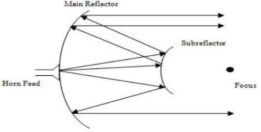
Figure 1: Basic Geometry of Cassegrain Antenna
For a Cassegrain system, the following factors affect the pointing precision [4]:
• Feed Displacement
• Displacement of Subreflector
• Vertex shift of Primary Reflector
To acquire and track a satellite in space, the earth station antennas should provide very accurate pointing information. Pointing error arises from
both the inability to aim an antenna in exactly the right direction and the inaccurate knowledge of target location. In this paper pointing errors and loss of gain caused by these above-stated factors is calculated for 1.5-meter Cassegrain antenna in 20 GHz frequency. The displacement of structures causes a change in path length of the rays in the main reflector. The pointing error and peak gain loss are calculated with respect to phase error
caused by a change in path length.
Table 1 Design Parameters of Cassegrain Antenna
Seq. no. Specifications Value
1 Main Reflector Diameter(D1) 1.5 meter
2 Sub reflector Diameter(D2) 0.1725 meter
3 Primary Focal Ratio 0.6
4 Cassegrain Focal Ratio 5.75
5 Beam Deviation Factor(K) 0.991
6 Magnification Factor(M) 8.7
[image:2.612.89.524.512.659.2]2. LITERATURE SURVEY
Mostly reflector antennas are used in satellite ground station because of its high gain (above 20dB). For reflector type antennas, the shorter transmission line connecting the feed point and transmitter or receiver equipment provide low loss. This can be achieved by using double reflector antenna (Cassegrain antenna). Cassegrain antenna offers low noise temperature, better pointing accuracy and flexibility in feed design than parabolic reflectors. Also, with the feed located near the vertex of primary reflector minimizes the transmission losses [5]. A Cassegrain antenna is a dual reflector antenna which consists of paraboloid main reflector, hyperboloid sub-reflector, and feed. The focal point of the paraboloid and virtual focal point of hyperboloid converges on the same point. Phase center of feed lies on the real focal point of sub-reflector. Usually, a horn antenna is the good choice as a feed for high-frequency applications whereas dipole antenna is the low-frequency counterpart. The energy from the feed illuminates the sub-reflector which reflects the signal energy to the main reflector. The reflected energy is again get reflected the by the main reflector to form a desired beam.
Double reflector system can be analyzed using physical optics (PO) principle. First, the current on the Subreflector surface is determined with the help of rays coming from the feed. After that, the Subreflector illuminates the main reflector from which induced currents can be determined. Finally, the total field can be computed by integrating all these currents [6].
The mispointing of antenna results in degradation of satellite link margin. The gain in the direction of
undesired satellite increases which creates
interference to that satellite downlink or uplink signal. This insisted the importance of installation technique of ground station for accurate pointing. Also, it emphasizes the value of beam bracketing method rather than simple peaking based on signal strength. Statistical pointing performance of the small earth station antenna is analyzed [7].
The beam characteristic of the main reflector antenna in the case the large lateral displacement of feed is computed using vector current method and scalar aperture theory [8].
In prime reflector antennas, the F/D ratio should not be very less than one consequently increasing the mechanical complexity of the antenna. This mechanical complexity can be compensated by
introducing double reflector system [9]. Cassegrain
and Gregorian are the examples of double reflector antenna configuration. The Gregorian system consists of ellipsoid Subreflector which increases the effective focal length of the system, but still there are some mechanical complexities due to the Subreflector position. On the other hand, Cassegrain system uses hyperbola as a secondary reflector which is placed between the main reflector and its focal length can reduce the overall length of the system since Subreflector can be placed near the main reflector.
Effect of surface distortion in radiation
characteristic of antennas using physical optics approximation is presented in [10]. Reflector antennas in the high-frequency application need more accurate surface since maximum operating frequency depends on the accuracy of the surface. For the system which requires optimum quality of performance, surface errors decrease the antenna radiation performance. The paper presented the relation between polarization coefficients and radiation pattern of the antenna. It is noticed that lower half of the offset paraboloid reflector is more vulnerable to surface distortions causing a change in radiation characteristic.
The beam distortions due to the displacement of feed in prime reflector antenna can be found by using optics. But, optical references are not directly interrelated with the antenna terminology describes how scalar plane wave theory can be used to study the beam characteristics of the prime reflector antenna [11]. Surface errors largely degrade the performance of antenna while working on the higher frequency band. Compensation methods to decrease the effect of aperture errors are presented [12].
3. METHODOLOGY
performance. On the other hand, the increase in F/D ratio causes a decrement in edge angle making the system to require more directive and large feed for uniform aperture illumination. Also, mechanical supporting structures create a blockage which reduces gain and increases sidelobe levels. To avoid this problem we can use dual reflector antenna system [13]. For generating apertures, dual reflector antenna gives more degree of freedom.
Beam Deviation Factor and Magnification Factor:
The ratio of beam maximum to offset angle is called beam deviation factor and it is denoted by K. The value of beam deviation factor (BDF) depends upon the F/D value of antenna [14]. The BDF approaches 1 as F/D approaches infinity. The approximate mathematical expression for BDF is given by:
The magnification factor of hyperbola can be written as:
Where is the eccentricity of the hyperbola which is always greater than one. Also, the magnification factor can be regarded as the ratio of main reflector diameter to sub-reflector diameter. The analysis of Cassegrain antenna can be done by modeling it as a single parabolic reflector (equivalent parabola) [4] [15]. The equivalent focal length (Fe) of parabolic
reflector increases by M times i.e. Fe .The
increase in equivalent focal length helps to decrease cross polarization.
Feed Displacement:
[image:4.612.189.442.410.609.2]The illumination energy provided by feed should distribute in a uniform manner in reflector surface. This implies amplitude and phase of the every incident signal should be same. Also, to be a good feed, the phase center should be located on the focal point of the primary reflector. Feed displacement can be categorized into two ways axial feed displacement and lateral feed displacement. Axial displacement occurs due to the shift of feed along the axis of reflector whereas for lateral defocus, the direction is perpendicular to the antenna axis [16].
Figure 3: Lateral Defocusing of Feed
The path length difference (ΔL) caused by axial defocus can be written as
The difference in path length results from phase
error over the aperture plane. Phase error (ΔØa) due
to path length difference (ΔL) is
From this phase difference, antenna field pattern can be derived [2]
Where
J0 is the zero order Bessel function, θ is the angle
from the axis and f (v) is the feed illumination function. Approximately, feed illumination function can be written as
T is taper coefficient which determines the percentage of feed illumination. Taper coefficient can be calculated as
When T is 1, the feed has uniform illumination over the aperture. In the same way, phase error due to lateral displacement is given by
By squaring the antenna field pattern we can get power pattern. Due to displaced focal point, the pointing error or corresponding beam deviation is
Figure 4: Lateral Defocusing of Subreflector
The above figure shows the displacement of
Subreflector with dLs distance along normal to the
axis. The pointing error caused by this scenario can be derived by calculating the location of the virtual focal point.
The pointing error (θh) becomes:
Similarly, the pointing error resulting from vertex
shift of system with distance dLv is,
The gain profile of the antenna due to a lateral and axial displacement of Subreflector (i.e. Hyperbola) can be calculated by replacing the exponential term in Eq 2.5 by phase error due to Subreflector. The
resulting antenna pattern due to lateral
displacement of feed and Subreflector can be calculated by:
Where, , and represents
displacement.
Pointing Loss:
The gain of the antenna is a key parameter of ground station antenna because it affects the satellite uplink and downlink energy. The pointing loss is defined as the amount of gain loss due to misalignment of antenna main beam [17]. The gain is optimum when there is no any pointing error or beam deviation. Half Power Beam width (HPBW) and Pointing error determine the amount of pointing loss. The HPBW for reflector type antennas is given by:
The loss of gain (Δ ) due to beam deviation degree is
3. RESULTS AND DISCUSSIONS
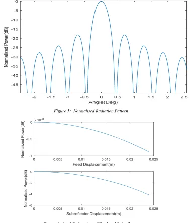
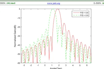
Figure 5 shows the normalized power pattern of Cassegrain antenna assuming constant phase over the aperture and uniform amplitude illumination. The on-axis gain (i.e. for v=0) profile of the antenna with feed and Subreflector displacement is shown in Figure 6. Structures (feed and
[image:7.612.125.503.189.634.2]sub-reflector) have been shifted up to 1 inch. For the same displacement, Subreflector translation is more vulnerable to gain loss than feed displacement. Shifting the feed in the axial direction of reflector axis causes under-illumination of the main reflector whereas Subreflector translation is responsible for the under-illumination of both Subreflector and main reflector.
[image:7.612.131.501.190.400.2]Figure 5: Normalised Radiation Pattern
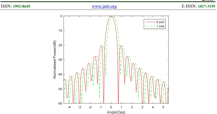
[image:7.612.161.449.349.619.2]Figure 7: Lateral Defocusing of Feed
In addition to beam deviation, lateral defocusing produces asymmetric side lobes called coma lobes which are the source of interference for other satellites. Shifting the structures in +ve Y-axis, the beam is shifted to the right. In a similar way,
[image:8.612.185.441.378.552.2]displacement in opposite direction causes the beam to shift in the left side. 0 inch in Figure 7 and Figure 8 represents the antenna pattern without displacement.
Figure 8: Lateral defocusing of Subreflector
Table 2: Measurement of Sidelobe Level
Displacement (Inch) Feed Shift Subreflector Shift
0 -20.44 dB -20.44 dB
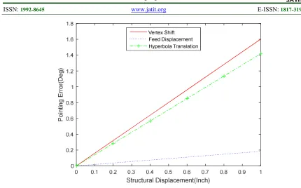
Figure 9: Pointing Error Vs Displacements
Lateral defocus increases the side lobe in the shifted direction and the reverse is true for opposite direction. The effect of lateral defocus on sidelobe level in the beam shift direction is listed in Table 2.
Figure 9 shows the pointing error caused by lateral displacements of feed, Subreflector, and vertex of the main reflector. These figures show the pointing error for various displacements ranging from 0 to 1
inch. The effect of feed displacement has a negligible effect on pointing errors while hyperbola translation and vertex shift shows significant impact on it. One inch shift of vertex causes about 1.6-degree pointing error. On the other hand, the same displacement of feed produces only
0.18-degree pointing error which is about 1/10th of
pointing error due to vertex shift.
For high-frequency reflector antenna, a horn antenna is used as a feed. The feed should have uniform amplitude and phase distribution over the aperture. But axial displacement of feed and
[image:9.612.87.526.511.647.2]Subreflector cause phase error over the aperture which is presented in Table 3. These phase errors introduce a loss in peak gain.
Table 3: Phase Error Due to Axial Defocusing
Displacement
(inch)
Phase error due to feed displacement(deg)
Phase error due to subreflector displacement(deg)
0 0 0
0.2 0.0097 0.6393
0.4 0.0195 1.2786
0.6 0.0292 1.9179
0.8 0.0390 2.5572
1 0.0487 3.1965
The pointing error causes pointing loss of antenna which we have to consider in satellite link budget. Figure 10 shows the relation between pointing loss and structural deviation. The point loss due to
Figure 10: Pointing Loss
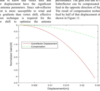
As we came to know that vertex shift and Subreflector displacement have the significant impact on antenna parameters. Since sub-reflector displacement is more susceptible to wind and temperature gradients than vertex shift, effective compensation technique is required for the Subreflector shift to optimize the antenna
performance. The gain loss due to the axial shift of Subreflector can be compensated by moving the feed in the opposite direction of Sub-reflector shift. The result of compensation technique shifting the feed by half of that displacement of sub-reflector is shown in Figure 11.
Figure 11: Compensation of subreflector shift (axial)
In the same way, to compensate the axial feed shift, Subreflector can be moved in opposite direction of feed shift. The amount of beam deviation and asymmetric sidelobe due to lateral displacement is a function of F/D ratio displacement. The lateral defocused effect can be
[image:10.612.134.457.336.632.2]Figure 12: Compensation of Subreflector Shift (Lateral)
4. CONCLUSION
Beam squint due to the structural deflection is calculated for 1.5m Cassegrain antenna for 20 GHz. Axial displacement is responsible for the loss of gain whereas lateral displacement is accountable for the pointing error. The effect of lateral defocus on the gain profile is
negligible. Vertex shift and sub-reflector
displacement have the significant role in distorting the pointing precision. For one inch displacement of vertex and Subreflector, the beam deviates by 1.6 and 1.4 degrees respectively. These beam deviation forces the antenna to miss the target resulting in pointing loss. Also, an inch lateral displacement of Subreflector results increment of the sidelobe level by 4.61 dB whereas for the same displacement of feed, the sidelobe level rises by
0.15dB. Pointing loss of antenna varies
exponentially with structural displacement. The feed displacement has a low impact on Cassegrain antenna performance. But in prime reflector case, it may have the significant impact.
For the optimum performance of
Cassegrain antenna, sub-reflector should be placed exactly in the prime focus of the main reflector.
The gain of the antenna can be increased from -4.14 dB to -0.99 dB by moving the feed in the opposite direction of Subreflector shift. The required feed shift is smaller than Subreflector shift. The pointing error can be reduced about 0.8
degrees by increasing the focal length of the system by 1.5 times. Also, the sidelobe level can be decreased by 2.52 dB for a one-inch Subreflector displacement (lateral) case.
5. ACKNOWLEDGEMENTS
The authors especially thank the support given from Department of Science and Technology (DST), Government of India through the funded project with F. No: SB/FTP/ETA-0175/2014. The authors also thank the management of KL University for supporting and encouraging this work by providing the facilities in Centre for Applied Research in Electromagnetics (CARE) of ECE.
REFERENCES
[1] D. E. M. G. J. Hawkins, “Tracking Systems For
Satellite Communication,” IEEE
Proceedings,Vol 135, pp. 393-407, (1988). [2] K. M. S. R.B. Dybdal, “Narrow Beamwidth
Satellite Antenna Pointing and Tracking,”
IEEE Antennas and Propagation, pp. 2012-15, (2011).
[3] D. V. Ralph Brooker, “Antenna Pointing Accuracy Impact on Geostationary Link
Quality and Interference,” in 23rd AIAA
[4] M. Zarghamee, “Peak Gain of a cassegrain
Antenna With Secondary Position
Adjustment,” IEEE Transactions on Antennas
and Propagation, pp. 1228-33, (1982).
[5] J. W. Lamb, “Analysis of a Cassegrian Antenna Having a Gaussian Illumination Pattern,” Helsinki University of Technology,Radio Laboratory, Otaniemi,Finland, (1983).
[6] B. D. Y. Y. Q. C. S. Wang, “Accurate Algorithm for Analysis of Surface Errors in Reflector Antennas and Calculation of Gain Loss,” in IEEE Symposium on Microwave, Antenna, Propagation and EMC Technologies for Wireless Communications, 2005.
[7] M. T. I. Y. Y. a. N. M. Md. Rezwanul AHSAN, “Ray Tracing Technique for Shaping a Dual Reflector Antenna System,” Turkish Journal of Electrical Engineering & Computer Sciences, vol. 24, pp. 1223-1234, 2016.
[8] A. F. Z. Na Li. Baoyan Duan, “Effect of the Random Error on the Radiation Characteristics of the Reflector Antenna Based on Two-Dimensional Fractal,” International Journal of Antennas and Propagation, 2012.
[9] R. H. J.A Battilana, “Gain Reduction of a Shaped Cassegrain Antenna Due to Lateral Displacements”.
[10] J. W. Lamb, “Analysis of a Cassegrain Antenna Having a Gaussian Illumination Pattern,” Helsinki University of Technology, Radio Laboratory, Otaniemi, Finland, 1983. [11] F. E. Zocchi, “Estimation of the Accuracy of a
Reflector Surface from the Measured rms Error,” IEEE Transactions on Instrumentation and Measurement, vol. 54, no. 5, pp. 2124-2129, 2005.
[12] J. R. B. a. L. P. Pereira, “Radiation Pattern Control by Subreflector Shaping in a Dual Reflector Antenna,” Microwave and Optical Technology Letters, vol. 35, no. 5, pp. 408-412, 2002.
[13] W. Baars, “Characteristics of a Reflector Antenna,” ALMA Memo 456, (2003).
[14] C. A. Balanis, Modern Antenna Handbook, A
John Wiley & Sons Publication, (2008).
[15] J. W. Baars, The Paraboloidal Reflector
Antenna in Radio Astronomy and
Communication, Springer, (2007).
[16] G. He, “Analysis of Feed Defocus's Effects on
a KA-Band Parabolic Antenna,” in
Proceedings of the 26th Conference of Spacecraft TT&C Technology in China, Beijing, (2013).
[17] K. RajaRao, Satellite Communication:
Concepts and Applications, PHI Learning Pvt. Ltd, (2013).
[18] Rakesh, D., et al. "Performance Evaluation of Micro Strip Square Patch Antenna on Different Substrate Materials." Journal of Theoretical & Applied Information Technology 26.2 (2011). [19] Kumar, K. Prabhu, et al. "Uniplanar
Quasi-Yagi Antenna for channel measurements at
X-band." Journal of Theoretical and Applied
Information Technology 26.2 (2011): 35-39. [20] Kavya, K. Ch Sri, Sarat K. Kotamraju, and
Habibulla Khan. "Calibration of linear array antenna using restoration technique with
near-field compressed sensing." Antennas and
Propagation (EuCAP), 2013 7th European Conference on. IEEE, 2013.
[21] B.T.P.Madhav, VGKM Pisipati1, Habibulla Khan, V.G.N.S Prasad, K. Praveen Kumar, KVL Bhavani and M.Ravi Kumar, “ Liquid Crystal Bow-Tie Microstrip antenna for
Wireless Communication Applications”,
Journal of Engineering Science and
Technology Review ISSN: 1791-2377 , 4 (2) (2011) 131-134.
[22] B.T.P.Madhav, VGKM Pisipati1, Habibulla Khan, V.G.N.S Prasad, K. Praveen Kumar,
KVL Bhavani and M.Ravi Kumar, “Liquid
Crystal Bow-Tie Microstrip antenna for Wireless Communication Applications”,
Journal of Engineering Science and
Technology Review ISSN: 1791-2377 , 4 (2) (2011) 131-134.
[23] B.T.P. Madhav, S.S. Mohan Reddy, J. Ravindranath Chowdary,V. Vinod Babu, S.S.
Satya Parthiva, S. Kalyana Saravana, “Analysis
of Dual Feed Asymmetric Antenna”, International Journal of Applied Engineering Research, ISSN 0973-4562 Volume 8, Number 4, June-2013, pp. 361-367.
[24] B.T.P.Madhav, S. S. Mohan Reddy, Bandi
Sanjay, D.Ujwala, “Trident Shaped Ultra
Wideband Antenna Analysis based on Substrate Permittivity”, International Journal of Applied
Engineering Research, ISSN 0973-4562,
Volume 8, Number 12, Nov-2013, pp. 1355-1361.
[25] B T P Madhav, Krishnam Naidu Yedla, G.S.,
Kumar, K.V.V., Rahul, R., “Fractal aperture
EBG ground structured dual band planar slot antenna”, International Journal of Applied
Engineering Research, ISSN 0973-4562,
[26] B. T. P. Madhav, Mounika Sanikommu, M. N. V. S. Pranoop, K. S. N. Manikanta Chandra
Bose and B. Sriram Kumar, CPW Fed Antenna
for Wideband Applications based on Tapered Step Ground and EBG Structure, Indian Journal of Science and Technology, ISSN: 0974-6846, Vol 8, Issue 9, May 2015, pp 119-127
[27] B. Sadasivarao, B. T. P. Madhav, “Analysis of
Hybrid Slot Antenna based on Substrate Permittivity”, ARPN Journal of Engineering and Applied Sciences, ISSN 1819-6608, Vol. 9, No. 6, June-2014, pp 885-890.
[28] B T P Madhav, K V V Kumar, A V Manjusha, P Ram Bhupal Chowdary, L Sneha, P Renu
Kantham, “Analysis of CPW Fed Step Serrated
Ultra Wide Band Antenna on Rogers RT/Duroid Substrates”, International Journal of Applied Engineering Research, ISSN 0973-4562, Volume 9, Number 1, Jan-2014, pp. 53-58
[29] B T P Madhav, K V V Kumar, A V Manjusha, P Ram Bhupal Chowdary, L Sneha, P Renu
Kantham, “Analysis of CPW Fed Step Serrated
Ultra Wide Band Antenna on Rogers RT/Duroid Substrates”, International Journal of Applied Engineering Research, ISSN 0973-4562, Volume 9, Number 1, Jan-2014, pp. 53-58