2017 2nd International Conference on Wireless Communication and Network Engineering (WCNE 2017) ISBN: 978-1-60595-531-5
Smart Fire Rescue System Design Based on WI-FI Mode
Xing-chen MING
Wuhan University of Science and Technology, Wuhan, Hubei, China
Keywords: Fire rescue, Smart, WI-FI mode, Design, Function.
Abstract. Fire timely remedy is very important for life and property safety. The fire intelligent technology and algorithm were adopted in the design according to the fire rescue system intelligent, rapid development in the future. The microcomputer is one of the most important equipment in this system which also includes electricity, source circuit, the motor drive circuit, photoelectric sensor, fire detection, fire fans, and other circuits. WI-FI mode can reduce the fire finding time, quickly start rescue system and rescue in time. The design production can realize some functions such as ultrasonic sensor obstacle avoidance, sensor identification of flame fire, obstacle avoidance automatically, remote control, ultrasonic obstacle avoidance, finding and extinguishing fire and so on.
Introductions
With the social development, the fires happen frequently and they are very dangerous for the social security and firefighting is a global problem. So the modern firefighting system has already become an extremely urgent and necessary need to address the problem [1]. As early as possible to pay attention to the fire and enter the fire scene, firemen will reduce the threat of fire and personnel safety.
A fire-fighting robot based on Wi-Fi smart car will help firefighters to rescue trapped people and reduce firefighters' risk. This design produces a simple fire car which can achieve the realization of onsite fire-fighting purpose. The short goal is the fire car that can react at first time, finding the fire point as soon as possible and sending the message out in the meantime in order to extinguish the fire more quickly. The equipment can also work in high temperatures, or even worse conditions [2].
We have completed the system hardware design including power supply module, MCU system, tracking system, motor drive system, barrier system, flame detection system and fire extinguishing system. We can realized some functions such as ultrasonic sensor obstacle avoidance, sensor identification of flame fire, obstacle avoidance automatically, remote control, ultrasonic obstacle avoidance, find and extinguishing fire, video capture and so on. We have optimized the algorithm in this design. This design can be used in many emergency situations, such as firefighting system, gas leaking system and many other extreme circumstances. Their general functions are similar, so here we focus on its fire-fighting application [3].
Design and Simulation
Topic request design a simple intelligent car model extinguishing the fire and can go to the designated area for firefighting work. The car must be conducted by information acquired by the internal equipment and then analyze and make corresponding action for field environmental situation in order to achieve the goal of intelligently putting out. This system mainly consists of the controller module, power module, DC motor and its driver module, obstacle avoidance module, extinguishing system and driver module and Wi-Fi module, this system block diagram as showed in figure 1.
The main part of the controller module is the STC89S51 microprocessor. The major function of the controller module is to analyze the information collected from other sensors module, send commands to motor module and then control the movement of the smart car. We program the codes of the computer and load them into the controller module [4].
people’s two legs in the system. The controller module controls the car’s speed and direction by adjust the pole and voltage of the motor. Environment information acquisition module, which is so-called sensors module, collect information from the environment and then send back to some module. Power supply module provides the necessary working power. The role of power module is how to allot and adjust the working voltage to every module correctly. The firefighting car which owns a Wi-Fi module is to build up a connection between the fire-fighting car and the user. If the emergency happens, sensor module needs to feedback and controller module sent alert to users through the Wi-Fi module immediately. The Wi-Fi module can also send video signal to users so that firemen are able to get more and concrete first-hand information. The infrared light electricity switch is used to avoiding obstacle. Obstacle avoidance module mainly based on information exchange between sensors and controller in order to control the motor module to adjust the car’s movement [5].
Figure 1. The whole system structure diagram.
Schematic Diagram
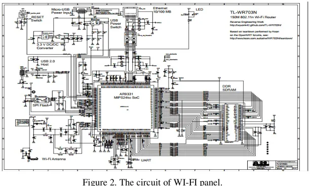
Wi-Fi panel is showed in figure 2:(1) a clean, small (57 mm × 57 mm ×18 mm) shiny white or light blue cover plastic case with rounded corners that is pretty easy to open with a spudger; (2) An atheros AR9331 chipset and an Atheros AR7040 400 MHz MISP24kc CPU, integrated 802.11n 150 Mbps (130 Mbps real) Wi-Fi with 20 dBm (100 mW) output power; (3) 4 MB of serial (SPI) flash memory; (4) 32 MB of DDR SDRAM; (5) An USB 2.0 host port; (6)a shielded ethernet 10/100 Mbps RJ45 jack; (7) an external power supply using a provided wall plug via a micro-USB socket; (8)a software-controlled reset pinhole switch; (9) a blue surface-mounted LED; (10) a built-in Wi-Fi printed antenna; (11) an UART accessible via 2 tiny pads that provides access to the u-Boot loader and the Linux 2.6 console.
Figure 2. The circuit of WI-FI panel.
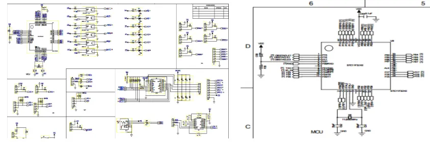
[image:2.612.155.462.536.720.2]board uses enhanced 51 kernel single-chip microcomputer, STC11F32XE, and it has 32 k Flash, 1280 - byte SRAM, the frequency of crystal oscillator is 22.1184 MHz Compared to traditional 51 MCU, it has the following features: 1) low power consumption, strong anti-interference, strong encryption; 2) support 1 t model, 22.1184 MHz about traditional single chip microcomputer frequency 265 MHz; 3) support the IAP technology, can be used to save the user data block 29 k EEPROM space; 4) have independent baud rate generator.
[image:3.612.91.513.146.286.2]
Figure 3. The circuit of main control panel. Figure 4. The control module simulation.
Control Module
This module can be used to control other function modules. The control module consists of three indispensable parts: power supply circuit, reset circuit and crystal circuit. The circuit functions are as follows: (1) power supply circuit: pin 38 positive is the pin VCC, provide +5 V voltages. Pin 17 is the pin GND, pin 20 and pin 17, together called power pin. (2) Crystal circuit: Crystal in the SCM system combines the internal circuit of the microcontroller to generate the clock frequency. The higher clock frequency the crystal provides, the faster the system runs. Our system uses 11.05MHz crystal oscillator as the oscillation source. Because there is a crystal circuit in the SCM Microsystems, so we just need one crystal and two capacitors in external circuit. Capacitance is 30pF. The influence of capacitor size in the oscillation frequency is very small, so we can use the capacitor size to change the oscillation frequency in a small size. (3) Reset circuit: The system need to be reset when the program is in a certain state of death cycle or the program out of control by some other reason. Pin 4 is the reset signal input. Keep the pin RST in a high-level two machine cycles, the system will be reset.
Obstacle Avoidance Module
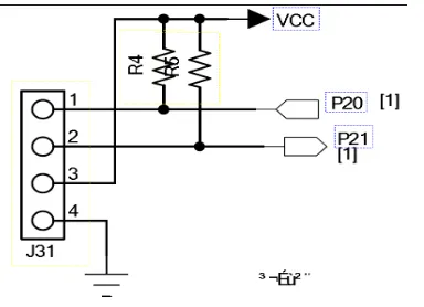
The left infrared detector is connected to P23, and the right detector is connected to P20. The schematic diagrams are shown in figure 5. We use dc to drive infrared detectors. If the laser beam of the right or left detector is blocked by the object, the car will stop immediately to avoiding dropping from the cliff.
Figure 5. Infrared obstacle avoidance module. Figure 6.Ultrasonic obstacle avoidance module.
Motor Driving Module
[image:4.612.307.509.77.208.2]Chip L298N is used as the motor driver chip and a high voltage, large current motor driver chip. The chip is encapsulated by 15 pins. The main features of the chip are high working voltage, the maximum working voltage with up to 46 V, high output current, instantaneous peak current with up to 3 A, continuous working current with 2 A and rated power with 25 W. The chip can drive a two phase stepper motor or four phase stepper motors and be driven by two dc motors using L298N chip drive motor.
Figure 7. Motor driving module simulation. Figure 8. Circuit of flame sensor.
Flame Detection Module
Flame sensor is used with infrared sensitive element AC4067 to detect infrared signal strength and converts it to the signal identified by the robot, thereby to detect flame signals. The feedback from flame sensor controls next step of the motors and the fan. The car should stop in front of the flame spot in an acceptable distance in order to make the fan towards the flame correctly.
Software Introduction
[image:4.612.82.531.335.469.2]Function Realization
The Control Module
We use STC chip named STC11F32XE, and the circuit is as the Figure 9. And the external circuits are integrated in a small PCB board, as figure 10 shows. For this chip we need to pre-define some ports for sensors, motors and some other functions. The source codes for pre-define ports are designed.
[image:5.612.297.523.157.310.2] [image:5.612.85.292.158.309.2]
Figure 9. Schematic diagrams of STC11F32XE. Figure 10. PCB Board.
The Obstacle Avoidance Module
In order to realize obstacle avoidance, we choose an ultrasonic wave sensor and a holder, then resetting the position of sensor to the middle and using the ultrasonic to send ultrasonic wave and calculating the distance between car and barrier. And the holder rotates up to left for 90 degrees firstly, then going back to the middle and rotating to right for 90 degrees finally. We use an array whose size is 3 to save the distance value of different directions and compare them, if the distance of one direction is the biggest, then control the motors of the smart car and rotate to that direction. We design some functions to implement the algorithm.
The Transmission of Video
We use the Wi-Fi module to connect the supervisor with smart car. The Wi-Fi module needs a firmware so that it can be used as a router. With the help of Linux, we can use the embedded system named as OpenWrt to create a firmware and then download to the Wi-Fi module. Instead of trying to create a single, static firmware, OpenWrt system provides a fully writable file system with package management. This frees you from the application selection and configuration provided by the vendor and allows you to customize the device through the use of packages to suit any application. For developer, OpenWrt system is the framework to build an application without having to build a complete firmware around it; for users this means the ability for full customization, to use the device in ways never envisioned. OpenWrt system is a highly extensible GNU/Linux distribution for embedded devices (typically wireless routers). Unlike many other distributions for these routers, OpenWrt is built from the ground up to be a full-featured, easily modifiable operating system for your router. In practice, this means that you can have all the features you need with none of the bloat, powered by a Linux kernel that's more recent than most other distributions.
With the help of OpenWrt, the PC can connect the Wi-Fi signal created by the router and we set a kind of special communication protocol, every time that we send command or transmit signals, we need follow the rules declared by the protocol.
The PC Client and the Android Application
The PC client owns some functions which it can monitor and capture the video transmitted by the lower computer. It can also send signals to the smart car or adjust the speed of the motor on the car. Besides, we can switch the mode of the smart car and even create some commands by user-define.
in this app, it has two functions, the first is monitor the video and the second is turn the fan on. The source code file directory of Android APP is designed.
Conclusions
A simple intelligent fire fighting vehicle with STC89C52 as the main controller is designed in paper. We use a variety of sensors to achieve the task target, such as infrared sensor, photo electronic sensor and flame sensor in order to be more accurate. At the beginning of the process, we figured out their parameters and prices, and found out the most suitable materials in this task. Furthermore, we designed the basic structure of this project like the overall simulating diagram and flow diagram. Then we prepared general schedules about the hardware design and software design, and combined them to develop the final process. In addition, we divided the task into serial small parts, such as infrared obstacle avoidance module, motor driving module, flame detection module and control module. In every module of the task, we figured out how to achieve the target function and write the related codes according to the design. Admittedly, we refer to a huge collection of references and codes that we will list in the end of the thesis. Then we made choices and comparisons and altered our codes according to these useful references. After that, we downloaded the codes to the main controller part and compiled and debugged to see whether it can realize the functions. A simple intelligent fire fighting vehicle that we have designed can react in the first time, finding the fire point, reducing the searching time, sending the message, transmitting the video image by Wi-Fi module. It has the ability of obstacle avoidance and tracking.
Reference
[1] K. Wang. Research on minimum system of single chip microcomputer [J].Qiuzhidaokan, 2015, (11): 56-57.
[2] J. Yao. Obstacle avoidance and path planning of autonomous ground vehicle. Southeast University for the Academic Degree of Master of Engineering, 2005.
[3] T. Yu. Design of smart car based on wireless mode. Nan Jing University of Science and Technology for the Academic Degree of Master of Engineering, 2015.
[4] Y. Ye, S. Ci, A.K. Katsaggelos. Wireless video surveillance: a survey [J]. IEEE Access 2013, 1: 646-660.