Temporary short circuit detection in induction motor winding using combination of
wavelet transform and neural network
D.A. Asfani
a,b,⇑, A.K. Muhammad
c, Syafaruddin
d, M.H. Purnomo
b, T. Hiyama
a aDepartment of Computer Science and Electrical Engineering, Kumamoto University, 2-39-1 Kurokami, Kumamoto 860-8555, Japan b
Department of Electrical Engineering, Intitut Teknologi Sepuluh Nopember, 60111 Surabaya, Indonesia c
Faculty of Electrical and Electronic Engineering, Universiti Tun Hussein Onn Malaysia, 86400 Parit Raja, Johor, Malaysia d
Department of Electrical Engineering of Universitas Hasanuddin, 90245 Tamalanrea-Makassar, Indonesia
a r t i c l e
i n f o
Keywords:
Temporary short circuit Induction motor winding Wavelet transform Neural network
a b s t r a c t
Monitoring system for induction motor is widely developed to detect the incipient fault. Such system is desirable to detect the fault at the running condition to avoid the motor stop running suddenly. In this paper, a new method for detection system is proposed that emphasizes the fault occurrences as tempo-rary short circuit in induction motor winding. The investigation of fault detection is focused on the tran-sient phenomena during starting and ending points of temporary short circuit. The proposed system utilizes the wavelet transform for processing the motor current signal. Energy level of high frequency sig-nal from wavelet transform is used as the input vriable of neural network which works as detection sys-tem. Three types of neural networks are developed and evaluated including feed forward neural network (FFNN), Elman neural network (ELMNN) and radial basis functions neural network (RBFNN). The results show that ELMNN is the most simply and accurate system that can recognize all of unseen data test. Lab-oratory based experimental setup is performed to provide real-time measurement data for this research. Ó2011 Elsevier Ltd. All rights reserved.
1. Introduction
Induction motors are the most widely used rotary machines in industrial sector for electrical to mechanical energy conversion due to the high development of operation control of motor system. About 70% of the industrial applications utilize induction machines and because of this trend they consume more than 50% of an indus-trialized power generating capability (Cusido, Rosero, Ortiga, Gar-cia, & Romeral, 2006). However, the induction motors are very easy to be damaged during their operations. In some industrial processes, the induction motors are often installed in the hostile environment that may be easily led to the deterioration. Moreover, several problems may occur during operation because of thermal, mechanical and electrical stresses. In spite of their reliability and robustness, they do occasionally fail with unpredictable downtime that causes obvious cost maintenance (Niu et al., 2008). Some stud-ies and site surveys show that 30–40% of induction motor failures are caused by stator winding breakdown because of lamination breakdown or stator winding defects (Siddique, Yadava, & Singh, 2005). In order to avoid huge risk of loss production, obvious cost
maintenance and also operator safety of industrial process because of sudden stop of motor failure, predictive maintenance and fault diagnosis is highly needed. For this task, on-line monitoring is commonly equipped to detect the fault symptoms. In recent years, research and development methods for on-line monitoring and incipient fault detection for induction motor, especially for wind-ing failure have been receivwind-ing wide attention. Mostly, motor cur-rent signal has pretty similar pattern as sinusoidal signal and occasionally changes gradually due to mechanical load changes. Therefore, the similarity of sinusoidal pattern results in the simi-larity of RMS value of the current. However, motor current signal trend is rapidly changed when the fault or short circuit occurs. Detection incipient fault such as small current short circuit in winding was proposed (D’angelo et al., 2011). Short circuit is de-tected by using combination of fuzzy system and Bayesian change point that use current signal as the input variable detection. Motor current pattern is modeled as time series based fuzzy-neural net-work and incipient fault is successfully detected by using charac-terize change point in that model. Another proposed model for fault diagnosis called neuro multi-step ahead predictor was pre-sented (Kim & Parlos, 2002). This proposed model combines model based and measurement based system. Residual signal is named to the signal that obtained from differentiate of measurement and prediction signal. Residual signal together with harmonics of
0957-4174/$ - see front matterÓ2011 Elsevier Ltd. All rights reserved. doi:10.1016/j.eswa.2011.11.048
⇑ Corresponding author at: Department of Computer Science and Electrical Engineering, Kumamoto University, 2-39-1 Kurokami, Kumamoto 860-8555, Japan. Tel.: +81 8039091404; fax: +81 963423630.
E-mail address:[email protected](D.A. Asfani).
Contents lists available atSciVerse ScienceDirect
Expert Systems with Applications
current signal is used as detection variable to distinguish normal and faulty conditions. The most popular method to detect the fault at induction machine is known as motor current signature analysis (MCSA). This method utilizes the frequency pattern of motor cur-rent to detect availability of faults. This method, however, does not always clearly detect the fault when the speed or load torque is not constant due to the non-stationary signal. In order to over-come this problem, Fourier transform is combined with wavelet transforms and power spectral density (PSD) techniques (Cusido, Romeral, Ortega, Rosero, & Garcia Espinosa, 2008). Fault in induc-tion motor may affect in many measurement parameters of motor such as current, flux and vibration, but the relationship of those parameters and the fault type are different in case by case. Such relationship is more complex in different loading cases or other operation conditions. Those complexity of motor faults let the researchers to apply the non-linear and adaptive solution to solve the problem. In order to obtain the significant parameter for detec-tion, some methods for classification and signal processing are used. Case based-reasoning (CBR) which is known as a technique uses implicit knowledge from previous case and experience to guide solving problem combined with Petri nets (PNs) is used to diagnosis induction motor faults. This system is capable to add the new cases and conducting revision to improve system capabil-ity (Yang, Jeong, Oh, & Tan, 2004). In other approaches, Fourier transforms combined with classification and regression tree (CART) as classification parameter and adaptive neuro fuzzy infer-ence system (ANFIS) as an adaptive detection system are utilized for fault diagnosis system (Tran, Yang, Oh, & Tan, 2009). Similar with detection system and fault diagnosis, on-line monitoring sys-tem for induction motor has reached excellent progress in their development methods. On-line monitoring based on motor current measurement was proposed (Acosta, Verucchi, & Gelso, 2006). Fre-quency spectrum analysis accompanied with the non-invasive technique which called the extended Park’s vector approach is used as detection system. The later techniques accurately detect the inter-turn short circuit. Another method is the simplified scheme for monitoring system based on spectrum analysis com-bined with fuzzy system (Rodriguez, Negrea, & Arkkio, 2008). In this scheme, the system is utilized by adaptive multistage filter to anticipate uncertainty noise signal. In order to optimize perfor-mance of this filter, several loading cases and noising input are trained. In this paper, a new method for on-line monitoring and fault detection system of induction motor winding are presented. The detection is emphasized on the transient phenomena during fault starting and ending points. This method is purposed to detect temporary short circuit in order to define the incipient of fault occurrence. This short circuit is specified as follow; temporary by means not permanently short circuit; low current that specified below 300% current rating; and non periodic occurrences. Beside the proposed method has simple calculation and implementation, it is also capable to detect temporary short circuit and to provide information about when the short circuit occurs accurately, such as at the fault starting and ending points. Combination of wavelet transform and neural network (NN) is designed to do this task. Wavelet transform is used as signal processing to obtain precious signal that contains the fault information. In this task, second level Haar wavelet transform is selected because it has simple calcula-tion method and is capable to extract the needed informacalcula-tion. En-ergy level of high frequency signal from wavelet transform is selected as the input signal of detection system. The optimal detec-tion system configuradetec-tion is developed and selected from three types of neural network, including feed forward neural network (FFNN), Elman neural network (ELNN) and radial basis function neural network (RBFNN). Several cases of temporary fault are tested and investigated in the laboratory experiment and current signal that contains the fault phenomena is recorded.
2. Configuration of proposed method
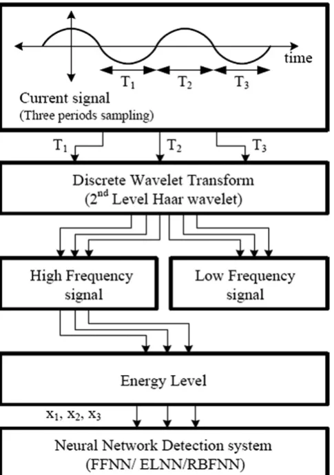
In this section, the proposed method using energy level of high frequency signal extracted by discrete wavelet transform and neu-ral network configuration for detection system will be explained. The flowchart of our proposed method is shown inFig. 1. In this figure, motor current signal is measured and converted to digital data. There are three periods of samplingT1,T2 and T3 used in the monitoring signal and each incoming signal will be simulta-neously processed in the sequent step. Furthermore, each signal is filtered using second level Haar wavelet transform and it may re-sult high and low frequency; but only the high frequency signal is used for further processing. After this step, the energy level all of three high frequency signals are obtained and the results arex1, x2, andx3. Finally, the last step is the fault detection system which consists of neural network system with the input variables arex1, x2 andx3 simultaneously.
2.1. Discrete wavelet transform
[image:2.595.308.551.389.734.2]Wavelet transform (WT) is known as an alternative method to analyze non-stationary signal beside the conventional method, short-time Fourier transform (STFT). When STFT is applied, the non-stationary signal is divided into small windows of equal time and Fourier transform is then applied to the time segment being examined. As the wide of windows function decreases, the greater time location is acquired but it will consider smaller portion of fre-quency information. On the other hand, when the windows function is increased, more accurate frequency information will increase but
the ability of method to determine the time when transient occur is decreased (Niu et al., 2008). In order to overcome the shortcoming of STFT, wavelet transform is introduced as an alternative solution to analyze the non-stationary signal that provides both frequency and time information simultaneously (Burrus, Gophinath, & Guo, 1998). Wavelet function is expressed using
w
() and should be satis-fying two basic properties as follows, the integral ofw
() is zero(1), and the square ofw
() integrates to unity(2)Z 1
1
wðuÞdu¼0 ð1Þ
Z 1
1
w2ðuÞdu¼1 ð2Þ
Wavelet transform consists of two functions, scaling functions, /(t) which is deducted by father wavelet and wavelet function,
w
(t) deducted by mother function. These functions are mathemat-ically expressed as follows:/j;kðtÞ ¼2 j=2
/ð2jtkÞ ð3Þ
wj;kðtÞ ¼2 j=2
wð2jtkÞ ð4Þ
Using these functions, some signals can be formed as low and high frequency signals,cj,kanddj,krespectively and reconstructed
to the origin signal
cj;k¼
Z 1
1
fjðtÞ /j;kðtÞdt ð5Þ
dj;k¼
Z 1
1
fjðtÞ wj;kðtÞdt ð6Þ
2.1.1. Haar wavelet
Haar wavelet is the oldest and simplest of all wavelets. The Haar wavelet has been known for hundred years and it has been used to solve various fields such as mathematics and engineering. The Haar wavelet and scaling function are defined as(7) and (8), respectively
wðtÞ ¼
1 fort20;12¼0
1 fort2 1
2;1
¼0
0; otherwise
8 > < >
: ð7Þ
/ðtÞ ¼ 1 for 0<t<1
0; otherwise
ð8Þ
Based on Haar wavelet and scaling function, Haar wavelet decomposition of digital signal x[k] at level jis described as in
(9)as follows:
cjðkÞ;djðkÞ ¼WT½nx½n ð9Þ
Low frequency signalcj(k) and high frequency signaldj(k) are
ob-tained by simple convolution the digital signalx[n] with wavelet transformWT[n]. For Haar purpose, the wavelet transform can be
defined as follows:
WT½n ¼ 1ffiffi
2
p 1ffiffi
2 p
1ffiffi 2
p 1ffiffi
2 p
" #
ð10Þ
Simple convolution of Haar wavelet is expressed in(11), where cj1can be the original signal
cjðkÞ djðkÞ
¼ 1ffiffiffi
2
p 1 1
1 1
c
j1ð2kÞ dj1ð2kþ1Þ
ð11Þ
From(11)we can obtain the low frequency signal ascj(k) and
[image:3.595.53.287.61.436.2]high frequency signaldj(k) as follows:
[image:3.595.309.557.456.739.2]Fig. 2.Feedforward neural network.
Fig. 3.Hidden layer.
cjðkÞ ¼
1 ffiffiffi 2
p ððð1Þcj1ð2kÞÞ þ ðð1Þcj1ð2kþ1ÞÞÞ ð12Þ
djðkÞ ¼
1 ffiffiffi 2
p ððð1Þcj1ð2kÞÞ þ ðð1Þcj1ð2kþ1ÞÞÞ ð13Þ
The first level decomposition of Haar wavelet transform is defined by substitutej= 1 in(14) and (15)
c1ðkÞ ¼ 1ffiffiffi 2
p ððc0ð2kÞÞ þ ðc0ð2kþ1ÞÞÞ ð14Þ
d1ðkÞ ¼ 1ffiffiffi 2
p ððc0ð2kÞÞ ðc0ð2kþ1ÞÞÞ ð15Þ
For the second level j= 2 the transformation can be obtained as follows:
d2ðkÞ ¼ 1ffiffiffi 2
p ððc1ð2kÞÞ þ ðc1ð2kþ1ÞÞÞ ð16Þ
Substitutec1(2k) andc1(2k+ 1) to(16); the high frequency sig-nal of second level decomposition can be calculated from the origi-nal sigorigi-nals
d2ðkÞ ¼ 1ffiffiffi 2
p ðc0ð4kÞ þc0ð4kþ1Þ c0ð4kþ2Þ c0ð4kþ3ÞÞ ð17Þ
2.1.2. Energy level
In this paper, the energy of high frequency signal is calculated as follows:
e¼X n¼k
n¼1 jyhigh½nj
2
ð18Þ
Energy values are used as input variables for developed artificial neural network which works as detection system for the tempo-rary fault in induction motor winding.
2.2. Artificial neural network (ANN)
During the last two decades, there has been a substantial in-crease in the interest on ANNs. ANNs have been successfully em-ployed in solving complex problems in various fields (Kirmaci, Menlik, & Ozdemir, 2010). In this paper there are three types of neural network are investigated to obtain the most suitable system for detecting temporary fault.
2.2.1. Feed forward neural network (FFNN)
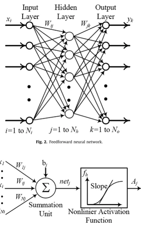
A feed forward neural network consists of a number of simple neuron which organized inlayers. Every neuron or node in a layer is connected with all the nodes in the previous layer. Each connec-tion may have a different value ofweightor strength. The weights on these connections represent the knowledge of a network. Data passes through the network until it arrives at the outputs. There is no feedback between layers so it calledfeedforwardneural net-works. The architecture of a FFNN with one hidden layer is shown inFig. 2.
The input layer consists of Np inputs. Each pth input is con-nected to the eachqth node of the hidden layer by a weighting fac-tor, Wpq. Each node in the hidden layer performs a nonlinear
transformation of its weighted input signals. The model of unitq in the hidden layer is shown inFig. 3.
The output of this neuron can be formulated as:
[image:4.595.36.282.67.273.2]Aq¼fhðnetqÞ ð19Þ
[image:4.595.306.544.565.739.2]Fig. 5.Radial basis function neural network.
Fig. 6.Experimental scheme.
Fig. 8.Current signal during temporary fault.
[image:5.595.107.496.354.450.2]Fig. 9.High frequency signal using 1st level Haar wavelet transform.
Fig. 10.High frequency signal using 2nd level Haar wavelet transform.
Fig. 11.High frequency signal square using 2nd level Haar wavelet transform.
[image:5.595.106.496.498.595.2] [image:5.595.112.495.644.736.2]wherefhis a nonlinear activation function in the hidden layer which
can be a bounded monotonic function such as hyperbolic tangent, sigmoid, semi-linear, etc. During training process, only the value of its slope is varied. Input offhisnetqthat can be formulated as:
netq¼
XNp
p¼1
Wpqxpþbq ð20Þ
wherexpis the input of unitpin the input layer;Wpqis the
weight-ing factor between neuronpof the input layer and neuronqof the hidden layer, respectively; andbqis the bias term of the neuron. All
the weighting factors and bias terms are adjusted during the train-ing process. The structure of the FNN output layer is similar to the hidden layer with the exception that the inputs of the output layer are the outputs of the hidden layer. The output of neuronrin the output layer can be formulated as:
yr¼foðnetrÞ ð21Þ
wherefois the nonlinear activation function in the output layer,netr
is equal to:
netr¼
XNh
p¼1
WqrAqþbr ð22Þ
andWqr is the weighting factor between neuronqin the hidden
layer and neuronrin the output layer (Sharif & Taylor, 2000).
2.2.2. Feed forward neural network (FFNN)
Unlike FFNN, Elman neural network architecture considers information about past data in recurrent connection which called context unit. Elman network configuration can be seen inFig. 4. The function learnt by the network can be based on the current in-puts plus a record of the previous states and outin-puts of the net-work. The Elman neural network is capable of providing the standard state-space representation for dynamic systems. This is the reason why this network architecture is utilized as a recurrent neural equalizer.
The Elman network has three layers, input, hidden and output. In the hidden layer and output layer nodes, the sigmoidal
activation function is used (Koker, 2006). The expression for the hidden layer output is given as
XqðkÞ ¼
1 1þexp bhqðkÞ þPNp¼1W
ph
pqðkÞIpðkÞ þPpN¼þNNþ11W ph
pqðkÞXpðk1Þ
ð23Þ
And the output as
YlðkÞ ¼
1
1þexp b0lðkÞ þ
PN1 q¼1W
h0 qlðkÞXqðkÞ
ð24Þ
whereN1is the number of hidden nodes.b
h
qðkÞare the biases of the
hidden nodeq; Wph
pqðkÞare the weights from the input to the hidden
layer,N2is the number of output nodes,WhoqrðkÞare the biases of the
output layer nodes.
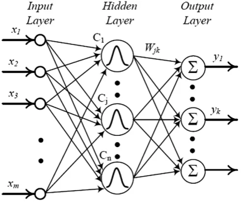
2.2.3. Radial basis function neural network (RBFNN)
Similar with two previous networks, an RBF neural network is consist of three layers; input layer, hidden layer and output layer. The network structure is shown inFig. 5. The inputsx1,x2,. . .,xm,
are connected to all neurons in the hidden layer. The hidden layer is composed ofn number of RBFs and connected directly to all nodes in the output layer. A node in the hidden layer will result a greater output if the input pattern presented is close to the center point of RBF. The output node will decrease as the distance from the center increases. Therefore only the neurons or node whose centers are close to the input pattern will produce nonzero activa-tion values to the input stimulus.
The basis function for theqth hidden node is often defined by a Gaussian exponential function calculated as follows:
hq¼hðvqÞ¼exp
v
2q
2
r
2q
!
ð25Þ
wheresigmaqis the width of theqth neuron,
v
qis usually selected [image:6.595.102.484.67.183.2]by the Euclidean norm of the distance between the input and the neuron center calculated as follows:
Fig. 13.Input variable neural network
Table 1
Data set.
Operation case Training and validation Testing
Number of cases Variation (A) Number of cases Variation (A)
Normal 40 1, 1.3 10 1.2, 1.5
Steady state S.C 100 2.75; 3.2; 3.6; 3.8; 4 10 3.5; 4.5
Starting S.C 100 2.3;3.1; 3.25; 3.75; 4 15 3.1; 3.6; 3.86
Ending S.C 100 2.3; 3.1; 3.6; 3.8; 4 15 2.4; 3.2; 4.5
[image:6.595.31.555.680.753.2]v
qðxÞ ¼ kxCqk ¼ffiffiffiffiffiffiffiffiffiffiffiffiffiffiffiffiffiffiffiffiffiffiffiffiffiffiffiffiffiffiffi Xm
p¼1
xpc2q;p
v u u
t ; i¼1;2; ::;m ð26Þ
wherex= [x1,x2,. . .,xm]T,Cqis the center of theqth RBF unit, which
is a vector whose dimension is equal to the number of inputs to the neuronq. The network architecture is shown inFig. 5. The network
output is formed by a linearly weighted sum of the number of basis functions in the hidden layer and can be calculated as follows.
yr¼
Xn
q¼1
wqrhq ð27Þ
whereyris the output of therth node in the output layer,wqris the
[image:7.595.93.517.63.219.2]weight from theqth hidden layer neuron to therth output layer
[image:7.595.49.550.270.490.2]Fig. 14.Mean square error of testing data.
Table 2
Network performance.
Network Data train Data validation Data test
SSE MSE SSE MSE SSE MSE
FFNN 2.871011
2.111014
6.93109
5.101012
2.7721 0.0139
ELMNN 0.0775 5.70105
0.1122 8.25105
0.6835 0.0034
RBFNN 5.321014 3.91
1017 0.7131 5.24
[image:7.595.76.532.508.637.2]104 16.5436 0.0827
Fig. 15.Detection using feedforward neural network (dot line is a target, solid line is a detection).
neuron, andhqis the output of the qth node in the hidden layer
(Zhang & Zhang, 2004).
3. Experimental set up and data generation
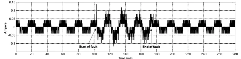
In this paper, laboratory scale experimental set up is performed consist of single phase induction motor 1/4 HP 1400 RPM, 50 Hz 110/220 V 4,8/2.4 A. Motor current is measured by Analog to Dig-ital converter and storage oscilloscope with 1 kHz sampling fre-quency. Variable resistance is inserted in this scheme for varying the short circuit case with different fault current. Experimental scheme and setup are shown inFigs. 6 and 7respectively. By using this set up, temporary short circuit is conducted and specified as short duration, less than 0.1 s and high impedance short circuit that produce low current short circuit, less than 300% power rating. Transient period during short circuit starting and ending occur are recorded. This transient period is used to detect the short cir-cuit occurrences in the proposed method.Fig. 8shows the current signal spectrum during temporary short circuit. The short circuit starts at 103 ms and disappears at 175 ms, which means the dura-tion of short circuit is 72 ms. In this cases short circuit current has low current level which has peak value of 4 A.
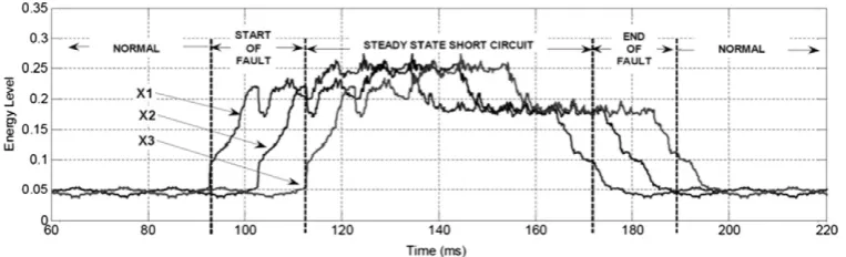
Figs. 9 and 10show high frequency of faulty signal using first and second level wavelet respectively. As shown in those figures, the second level wavelet transform is more clearly able to distin-guish the starting and ending points of fault.Fig. 11shows the high frequency signal square of second level wavelet transform. The sig-nificant difference of magnitude value for normal and faulty cases is provided in this figure. Moreover, the square value is then used to energy level calculation in the next step.Fig. 12shows the en-ergy level graph in whole of signal inFig. 8. Energy level is obtained using(18)which has period sampling is 10 ms or half cycle current waveform. As shown in this figure, the energy level during normal operation is mostly less than 0.1, but during fault period mostly more than 0.1. In addition, when the short circuit starting occurs, the energy level increases gradually from normal into fault and the opposite when the short circuit disappears, the energy level is decreased from fault to the normal.Fig. 13shows the input var-iablex1,x2 andx3. Actually, these variables come from the same signalx3 but delayed by 20 ms and 10 ms forx1 andx2, respec-tively. When we concern to all of these three variables in the
similar time, we can see that the normal condition is indicated by almost same low level of energy and fault condition is indicated by same high level energy. Moreover, transient starting short cir-cuit is indicated by low, medium and high level energy forx1,x2 andx3, respectively. Conversely, the ending of short circuit has trends of high, medium and low level forx1,x2 andx3. By using this common trending approach, the neural network inputs are decided to bex1,x2 andx3.
In order to construct neural network detection system, 730 operating condition are recorded varied by short circuit current le-vel. Data is divided into three following parts; training data, valida-tion data and testing data. Training and validavalida-tion data have similar short circuit level but they are different for testing data. The detail information about the data is shown inTable 1.
4. Neural network design
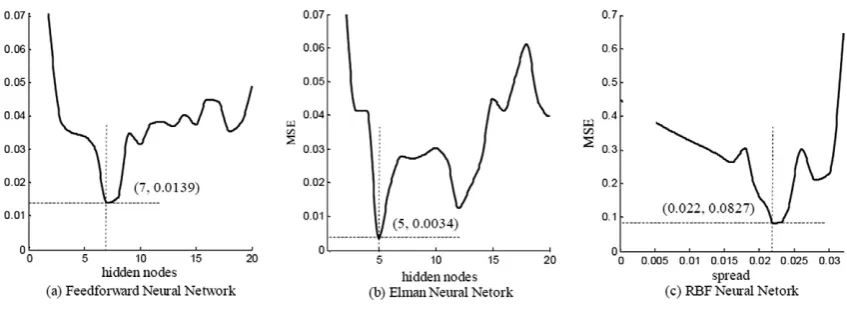
Feed forward, Elman and radial basis function neural networks are evaluated to achieve the best performance detection. Each type of neural network is designed as three layer networks consist of in-put layer, single hidden layer and outin-put layer. Inin-put layer and out-put layer consist of three and four nodes, respectively. In order to obtain most appropriate number of hidden node, various numbers of hidden nodes were tested.Fig. 14shows the performance of the network as a function of number of hidden node and spread. The best performance of FFNN is achieved when number of hidden nodes is 7 and gives 0.0139 mean square error (MSE) of data test. On the other hand, ELMNN achieves the minimum MSE of 0.0034 with 5 hidden nodes and RBFNN optimum design is achieved with 0.022 and 00827 for spread and MSE, respectively.
[image:8.595.67.518.65.194.2]Table 2shows more detailed performance of best of design net-work each types. All of the investigated netnet-works result in accept-able MSE value of data training. Better value of performance for data training is given by FFNN and RBF but for data test ELMNN gives the best result. This result concludes that ELMNN is more sim-ply and accurately than other typical artificial neural networks for detection system of temporary short circuit fault. In other results, the RBFNN may produce the best MSE training process but not for data testing. It is due to the instability network during the valida-tion process and also the overfitting condivalida-tion of the network.
[image:8.595.35.552.696.754.2]Fig. 17.Detection using RBF neural network (dot line is a target, solid line is a detection).
Table 3
Detection efficiency.
Network type Normal Steady state fault Starting fault Ending fault Efficiency (%)
TD FD TD FD TD FD TD FD
FFNN 49/50 1/50 48/50 2/50 48/50 2/50 50/50 0/50 97.5
ELMNN 50/50 0/50 50/50 0/50 50/50 0/50 50/50 0/50 100
5. Detection system analysis
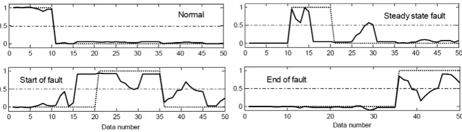
Detection results of the selected neural network are presented inFigs. 15–17. Designed neural network has four outputs that pre-sented four operating condition, normal, steady state fault, start of fault and end of fault. If motor running under normal operation, the value of first output is one and others output are zero. While steady state short circuit exists in motor winding, the second output value will be one and other outputs are zero. Furthermore, the outputs are (0 0 1 0) and (0 0 0 1) for starting and ending of fault, respectively.
Implementation the FFNN to 50 cases data test is shown in
Fig. 15. The first output is the detected normal condition which should be resulted one for data number 1 until 15 and zero for data number 16–50. But as shown inFig. 15, one case is false detection, case number 8 which resulted 0.5. Using threshold 0.5 to distin-guish false and true detection, it can be summarized that one of 50 testing cases is false detection (FD) and 49 of 50 cases is true detection (TD). The summarized over all cases and network is pre-sented inTable 3. Network efficiency is calculated as mean of TD. The best efficiency is given by ELMNN with almost 100% TD, while 97.5% and 87.5% for FFNN and RBFNN, respectively.
6. Conclusion
This paper describes the potential to combine the artificial neu-ral network methods with wavelet transform approach to detect temporary short circuit in induction motor winding more accu-rately. Temporary short circuit is defined as short time occurrences and low current level short circuit. In this proposed method, detec-tion based on transient starting and ending short circuit using en-ergy level is presented. Enen-ergy level is obtained from high frequency signal of second level Haar wavelet transform. Experi-mental setup is performed to obtain 730 data set varied by short circuit level. These high energy levels are used as the input signals for developed and investigated artificial neural network. Three types of neural network, such as feed forward, Elman and radial ba-sis function neural networks have been evaluated for fault detec-tion system. Each network is designed using 3 input nodes, 4 output nodes and different optimal hidden layers. In order to ob-tain the best design of network, the number of hidden nodes and spread are tested and evaluated using Mean Square Error (MSE)
value of unseen testing data. The result showed that Elman neural network with 5 hidden layers gives almost 100% accuracy of detection.
References
Acosta, G. G., Verucchi, C. J., & Gelso, E. R. (2006). A current monitoring system for diagnosing electrical failures in induction motors.Mechanical Systems and Signal Processing, 20, 953–965.
Burrus, C. S., Gophinath, R., & Guo, H. (1998).Introduction to wavelet and wavelet transforms. New Jersey: Prentice Hall.
Cusido, J., Rosero, J. A., Ortiga, J. A., Garcia, A., & Romeral, L. (2006). Induction motor fault detection by using wavelet decomposition on dq0 components. InIEEE ISIE 2006, Montreal, Quebec, Canada(pp. 2406–2411).
Cusido, J., Romeral, L., Ortega, J. A., Rosero, J. A., & Garcia Espinosa, A. (2008). Fault detection in induction machines using power spectral density in wavelet decomposition.IEEE Transactions on Industrial Electronics, 55(2), 633–643. D’angelo, M. F. S. V., Palhares, R. M., Takahashi, R. H. C., Loschi, R. H., Baccarini, L. M.
R., & Caminhas, W. M. (2011). Incipient fault detection in induction machine stator-winding using a fuzzy-Bayesian change point detection approach.
Applied Soft Computing, 11(1), 179–192.
Kim, K., & Parlos, A. G. (2002). Model-based fault diagnosis of induction motors using nonstationary signal segmentation. Mechanical System and Signal Processing, 16, 223–253.
Kirmaci, V., Menlik, T., & Ozdemir, M. B. (2010). Determination of freeze-drying behaviors of apples by artificial neural network. Expert Systems with Applications, 37(12), 7669–7677.
Koker, R. (2006). Design and performance of an intelligent predictive controller for a six-degree-of-freedom robot using the Elman network.Information Sciences, 176(12), 1781–1799.
Niu, G., Widodo, A., Son, J. D., Yang, B. S., Hwang, D. H., & Kang, D. S. (2008). Decision-level fusion based on wavelet decomposition for induction motor fault diagnosis using transient current signal.Expert Systems with Applications, 35, 918–928.
Rodriguez, P. V. J., Negrea, M., & Arkkio, A. (2008). A simplified scheme for induction motor condition monitoring.Mechanical Systems and Signal Processing, 22(5), 1216–1236.
Sharif, S. S., & Taylor, J. H. (2000). Short-term load forecasting by feed-forward neural networks. In Proceedings of the IEEE/ASME first international energy conference (IEC 2000), Al Ain, United Arab Emirates. <http://www.ee.unb.ca/ jtaylor/Publications/iec2000>.
Siddique, A., Yadava, G. S., & Singh, B. (2005). A review of stator fault monitoring techniques of induction motors.IEEE Transactions on Energy Conversion, 20(1), 106–114.
Tran, V. T., Yang, B. S., Oh, M. S., & Tan, A. (2009). Fault diagnosis of induction motor based on decision trees and adaptive neuro-fuzzy inference.Expert Systems with Applications, 36(2), 1840–1849.
Yang, B. S., Jeong, S. K., Oh, Y. M., & Tan, A. C. C. (2004). Case-based reasoning system with Petri nets for induction motor fault diagnosis. Expert Systems with Applications, 27(2), 301–311.