Fuzzy Controller Design of Lighting Control System by
Using VI Package
*
K.Saravanan,
**N.Muthu Prabhu,
**B.Raja Rajeswari
*
Assistant professor, department of EEE, Ranganathan Engineering College, Coimbatore, Tamilnadu, India **
Ug Student, Sasurie Academy of engineering, Coimbatore, Tamilnadu, India
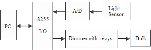
Abstract- This paper describes how we design a lighting control sys- tem including hardware and software. Hardware includes Dimmer with relays Bulb light sensing circuit, control circuit, and 8255 expanding I/O circuit, PC, and bulb. Sensing circuit uses photo-resistance component to sense the environmental light and then transmit the signal of the lightness to the computer through an 8-bit A/D converter 0804. The control circuit applies reed relay in digital control way to adjust the variable resistor value of the traditional dimmer. Software incorporates LABVIEW graph- ical programming language and MATLAB Fuzzy Logic Toolbox to design the light fuzzy controller. The rule-base of the fuzzy logic controller either for the single input single output (SISO) system or the double inputs single output (DISO) system is developed and compared based on the op- eration of the bulb and the light sensor. The control system can dim the bulb automatically according to the environmental light. It can be applied to many fields such as control of streetlights and lighting control of car’s headlights and it is possible to save energy by dimming the bulb. Experimental results show that the fuzzy controller with the DISO system can make bulb response faster than with the SISO system under sudden change of environmental light.
Index Terms- LabVIEW, lighting control system, MATLAB Fuzzy Logic Toolbox, fuzzy logic controller, SISO, DISO.
I. INTRODUCTION
fter Lotfi Zadeh had introduced the fuzzy logic in 1965, the fuzzy control method is extensively used since it has the advantage of being model-free without any a priori informa- tion required. It is easy to design a fuzzy control system with requisite knowledge and the experience of a skilled operator. Many issues focus on determining fuzzy control rules, mem- bership functions, and structures of fuzzy controllers [2, 4, 6]. Various ways of fuzzy logic used to improve industrial control [5] and methodology to reduce the number of variables
The application of fuzzy logic in lighting control has been presented in a number of papers. For example, it is possible to save energy by dimming the bulb or the fluorescent lamp. Dimming of the fluorescent lamp can be done by changing the input frequency of the electronic ballast [1]. A microproces- sor-based intelligent control device for streetlight control applying fuzzy decision theory to distinguish various interfe- rences accurately and to make it operate reliably, which can turn on or off the transformer automatically according to en- vironmental light [7].
Section II introduces the proposed lighting control system including hardware design. One of the important problems involved with the design of fuzzy logic controllers is the de- velopment of fuzzy if-then rules for fuzzy controllers. Section III presents the design method of fuzzy logic controllers. The experimental results and discussions are shown in Section IV.
II. SYSTEMDESCRIPTION
[image:1.612.317.570.192.277.2]The block diagram of the proposed lighting control system is shown in Fig. 1, which can be represented by a simple form like Fig. 2. The 8255 I/O shown in Fig. 1 is the expanding I/O circuit of a PC printer port. Originally, only 8-bit I/O in PC
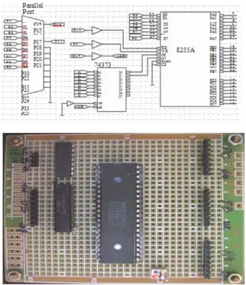
Fig. 3. The 8255 expanding I/O circuit connected with a PC printer port.
printer port can be used. After the 8255 expanding I/O circuit shown in Fig. 3 had been established, we have 24-bit I/O available now. The bulb drive shown in Fig. 2 is basically composed of a dimmer with 6 reed relays, and its corres- ponding hardware circuit is shown in Fig. 4. The reed relays in the bulb drive are regarded to as digital outputs of the light control system, thus the D/A converter is unnecessary for our case. One more thing need to be done is to design a parallel set of resistor circuit work as the function of the variable resistor in the dimmer. The main objective of designing a paral- lel-resistor circuit is to make the total resistance decreases homogeneously with the increase of the DN value of the con- trol output. Figure 5 shows the hardware layout of the paral- lel-resistor circuit, and it stands for one of the many possible solutions as long as the above requirement (homogeneously decreasing) can be met. The simulation result of the total resistance versus control output is shown in Fig. 6. The sensor block in Fig. 2 corresponds to the combination of A/D block and the Light sensor block, its hardware circuit is shown in Fig. 7, which contains photo-resistor CdS sensor and an 8-bit A/D converter and LED displaying circuit. Consequently, the hardware layout of the lighting control system is shown in Fig. 8. After all the hardware works had been done, subse- quently, our goal is to design a FLC used to dim the bulb ac- cording to the environmental light.
III. FUZZYLOGICCONTROLLER
the double inputs single output (DISO) system are discussed. The environmental light is used as input variable x1 for the SISO system, while another input variable x2 (the changing
rate of the environmental light) is considered for the DISO system. The output variable is the numerical value DN to the output circuit. The input variables are fuzzified by assigning them a singleton fuzzy set, i.e. a set with membership function µ and zero elsewhere. The fuzzy set of the output variable is
inferred by the max-min composition and the fuzzy relation describes the desired control action. The fuzzy set of the output variable is defuzzified to deliver a crisp numerical value by the center-of-gravity method. The fuzzy rule base consists of a collection of fuzzy IF-THEN rules of the form.
R(k): IF x1 is and x2 is F k , THEN y is Gk,
for k = 1, 2, …, n (1)
Where x1, x2 ∈ U, and y ∈ R are the input and output of the fuzzy sets in U1, U2 and R representing the kth antecedent pairs and consequent pair respectively and n is the number of rules. The SISO system and the DISO system will be discussed and analyzed by using MATLAB Fuzzy Logic Toolbox in the followings.
1. SISO
membership functions are given in Table 1. The rules base, with its 3 rules, is shown in Table 2.
Figure 10 shows the results of the simulation of the rule base by fuzzy inference development environment (MATLAB Fuzzy Logic Toolbox) software for the input value of the environmental light x1 = 164. The output is 24.22. Here only two rules are needed to calculate the output. The inferred
output solved by the center-of-gravity method can also be checked by hand calculation as follows:
2. DISO
Fig. 13. The result of the simulation of the DISO system using surface viewer of MATLAB fuzzy logic toolbox.
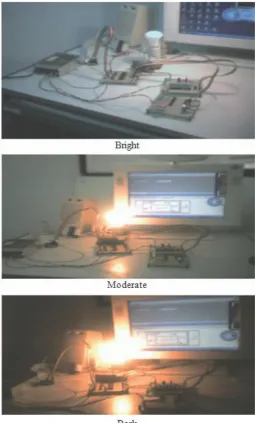
Fig. 14. Bulb responses for control value DN = 5, 15, 25.
software for the input values of the environmental light x1 = 150 and the changing rate of the environmental light x2 = 5. The output is about 9.41. Here only six rules are needed to calculate the output. The surface shown in Fig. 13 is the con- trol surface. It means that for every possible value of the two inputs, there is a corresponding output based on the rules. For example, if the environmental light x1 and the changing rate of the environmental light x2 are given, the control output DN of the system can be obtained immediately.
IV. RESULTSANDDISCUSSION
The light control system is constructed in a PC base using the 8255 expanding I/O circuit instead of a DAQ card. The 8255 I/O expanding circuit, sensing circuit, and the output control circuit become the requisite components in the design of a light control system. The resolution of A/D device is 8-bit and the digital outputs used only 6-bit. The tasks of acquiring the input signal, process of the input data, and output of the DN are commanded by using LabVIEW, which is a graphical programming language to accommodate the light control system. Figure 14 shows the corresponding bulb responses for the control value DN = 5, 15, 25 respectively. Figure 15 shows the change of the lightness of the bulb against the variations of the environment lightness.
The front panel and the block diagram of the LabVIEW program are shown in Fig. 16. At begin, we create a combo box with two items (SISO and DISO) in the front panel of LabVIEW, shown in the upper part of Fig. 16. To simplify the whole program, we make two sub-vi’s icons denoted as FLC
[image:5.612.45.289.236.303.2]Fig. 16. Front panel and block diagram in LabVIEW.
SISO and FLC DISO to do the corresponding job of the FLC, shown in the lower part of Fig. 16. After that, we can easily run the LabVIEW program and choose the item in the combo box and even switch the item to another one during the ex- ecution of the LabVIEW program.
The main features in the design of the light control system using the LabVIEW are:
(1) Low cost.
(2) Easy implemented in a PC without any DAQ card.
(3) Incorporate MATLAB Fuzzy Logic Toolbox with Lab- VIEW program.
Javidbakht [1] used fuzzy controller with the SISO sytem to dim the fluorescent lamp based on the availability of the outside light. And Zhang [7] adopted fuzzy controller with the DISO system to distinguish environmental interferences, avoiding the fault action and jittery and improving the reliability. In this paper, both the SISO system and the DISO system are discussed respectively in the fuzzy controller. The experimental results show, due to the light signal and the changing rate are considered, the DISO system responses faster than the SISO system when environmental light changes suddenly. It has also verified the effectiveness and robustness of the proposed fuzzy controller.
V. CONCLUSIONS
Important hardware such as the light sensing circuit and the dimmer with relays (like parallel-resistor circuit) were de- signed and proved work well. The control device can be used to adjust the light level of the bulb, making relays engaged or disengaged and saving the power. The device is reliable and convenient for maintenance.
The control of the bulb light system using a fuzzy logic controller is presented. Both the SISO system and the DISO system are discussed in the fuzzy logic controller and the LabVIEW program incorporated with MATLAB Fuzzy Logic Toolbox for the FLC is carried out. The experimental results have shown the satisfactory response of the bulb system against sudden change of the environmental light. This intel- ligent dimming device can also be applied to dim the bulb of the streetlights or car’s headlights automatically according to environmental light, which worked reliably and had obtained good effect of energy saving.
REFERENCES
[1] Javidbakht, Saeid, Design of a Controller to Control Light Level in a Commercial Office, M.S.Egr. Thesis, Department of Electrical Engi- neering, Wright State University, pp. 1-106 (2007).
[2] Mamdani, E. M., “Application of fuzzy algorithms for control of simple dynamic plant,” IEE Proceedings, Vol. 121, No. 12, pp. 1585-1588 (1974). [3] Mamlook, R., Tao, C. W., and Thompson, W. E., “An advanced fuzzy
controller,” Fuzzy Sets and Systems, Vol. 103, pp. 541-545 (1999). [4] Takagi, T. and Sugeno, M., “Fuzzy identification of systems and its
applications to modeling and control,” IEEE Transactions on Systems, Man and Sybernetics, Vol. 15, No. 1, pp. 116-132 (1985).
[5] Van der Wal, A. J., “Application of fuzzy logic control in industry,” Fuzzy Sets and Systems, Vol. 74, pp. 33-41 (1995).
[6] Wu, Z. Q., Wang, P. Z., and Wang, H. H., “A rule self-regulating fuzzy controller,” Fuzzy Sets and Systems, Vol. 47, pp. 13-21 (1992).
[7] Zhang, C., Cui, N., Zhong, M., and Cheng, Z., “Application of Fuzzy Decision in Lighting Control of Cities,” 44th IEEE Decision and Control Conference, Seville, Spain, pp. 4100-4104 (2005).
AUTHORS
First Author – K.Saravanan, Assistant professor, department of
EEE, Ranganathan Engineering College, Coimbatore, Tamilnadu, India, Email:[email protected]
Second Author – N.Muthu Prabhu, UG Student, Sasurie
Academy of engineering, Coimbatore, Tamilnadu, India, Email: [email protected]
Third Author – B.Raja rajeswari, UG Student, Sasurie