Available Online at www.ijergs.in
Volume - 4, Issue - 6, November - December - 2018, Page No. 122 - 131
Corresponding Author: Jaya Gupta, Volume -4, Issue - 6, November – December 2018, Page No. 122 - 131
Pag
e
122
VLSI Implementation and Performance Evaluation of Low Pass Cascade & Linear Phase FIR Filter
1
Jaya Gupta. Assistant Professor in EE, Arya Institute of Engineering Technology & Management, Jaipur (Raj.), India
2
Sadaf Siddiqui, Assistant Professor in EE, Arya Institute of Engineering Technology & Management, Jaipur (Raj.), India
3
Arpan Shah, Assistant Professor Department of ECE, Jagan Nath University, Jaipur, India
4
Ramesh Bharti, Associate Professor Department of ECE, Jagan Nath University, Jaipur, India
E-mail: [email protected], [email protected]
Abstract
In this Paper, we present a VLSI implementation of the low-pass-phase and cascade FIR filter for the low-power design.
Dynamic power can be controlled by the power supply. We have proposed a VHDL implementation of the low-pass FIR
filter. A discrete system output is transmitted to MATLAB to generate the frequency response. To make the pipeline more
synchronous, we use a ROM based on arrays to store the output between stages. An FIR is brought into a linear and a
cascade phase in the system and the energy consumption and the frequency response are analyzed.
Keywords: FIR, Dynamic power, ROM
Introduction
A finite impulse response (FIR) filter is a filter whose impulse response is of finite duration or response to any finite
length input, because it settles to zero in finite time[1]. The impulse response of an Nth-order discrete-time FIR filter lasts
exactly N + 1 sample from first nonzero element through last nonzero element, before it then settles to zero.FIR filter
can be discrete-time or continuous-time and digital or analog [2].FIR filter output is shown by following equation.
(1)
x[n] represents the filter input.Hk represents the filter coefficients[n] represents the filter output. N is the number of filter
coefficients (order of the filter).On taking z-transform of the above equation we get
(2)
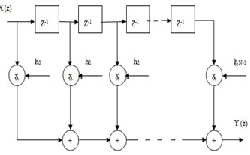
The equation of Y (z ) can be directly represented by a block diagram as shown in fig 1 and this structure is called
Directform structure or Fd.R filter [3]. The direct form structure provides a direct relation between time domain and
© IJERGS, All Rights Reserved.
Pag
e
123
Pag
e
123
Pag
e
123
Pag
e
123
Pag
e
123
Pag
e
123
Pag
e
123
Pag
e
123
Pag
e
123
Pag
e
123
Pag
e
123
Pag
e
123
Pag
e
123
Pag
e
123
Pag
e
123
Pag
e
123
Pag
e
123
Pag
e
123
Pag
e
123
Pag
e
123
Pag
e
123
Fig 1 Direct Form structure of FIR Filter
The frequency response of FIR filter is presented by H d (ejω ). So the equation for DFT coefficients H (k)
can be written as:
(3)
The samples of impulse response h (n) is given by,
(1) When N is odd,
(4)
(2) When N is even,
(5)
Now the Transfer Function H (z) of the filter is given by z- transform of h (n).
(5)
The magnitude response H (e jω)is given by A(ω),where
© IJERGS, All Rights Reserved.
Pag
e
124
Pag
e
124
Pag
e
124
Pag
e
124
Pag
e
124
Pag
e
124
Pag
e
124
Pag
e
124
Pag
e
124
Pag
e
124
Pag
e
124
Pag
e
124
Pag
e
124
Pag
e
124
Pag
e
124
Pag
e
124
Pag
e
124
Pag
e
124
Pag
e
124
Pag
e
124
Pag
e
124
(7)
The frequency response H
(
e
jω) is given by,(8)
Cascade and Linear Phase Fir Filter
A. Cascade FIR Filter
The transfer function of a FIR system,
(9)
The transfer function of FIR system is (N-1)th order polynomial in z. As a alternative to the Direct form [4], this polynomial can be factorized into first and second order factors and the transfer function H (z) can be expressed as a product of first and second order factors or sections as shown in equation [5],
(10)
© IJERGS, All Rights Reserved.
Pag
e
125
Pag
e
125
Pag
e
125
Pag
e
125
Pag
e
125
Pag
e
125
Pag
e
125
Pag
e
125
Pag
e
125
Pag
e
125
Pag
e
125
Pag
e
125
Pag
e
125
Pag
e
125
Pag
e
125
Pag
e
125
Pag
e
125
Pag
e
125
Pag
e
125
Pag
e
125
Pag
e
125
The individual second order or first order sections can be realized either in direct form structure or linear phase structure
[6]. The overall system is obtained by cascading the individual sections as shown in fig 2. The number of calculations
and the memory requirement depends on the realization of individual sections [7].
Fig 3 Block Diagram of Implementation of Cascade FIR Filter
Algorithm:
1. We calculate the coefficients with the help of following formula using MATLAB.
2. In VHDL implementation, find the output of first stage as H1 (z).
a) Multiply the input with coefficient. Mn = X(z) * hn
b) Now add all the multiplicants to find the output of first stage.
3. Similarly in next two stages of cascade structure we repeat the 2nd step.
4. Thus we calculate the output of last stage as final output Y (z).
5. Now frequency response generated by using MATLAB. B. Linear phase FIR Filter
If the impulse response is symmetric about its origin, linear phase results. If all zero filter has a linear phase response, a
special non-recursive structure that reduces the number of multiplications by approximately one half can be
implemented. The impulse response for a casual filter begins at zero and ends at N-1 [8].
A. linear phase FIR filter of length N is characterized by
h(n)= h(N −1− n)
The symmetry property of a linear phase FIR filter is used to reduce the multipliers required in these realization [9].
Using this condition, the z-transform of the impulse response can be expressed as:
(11)
© IJERGS, All Rights Reserved.
Pag
e
126
Pag
e
126
Pag
e
126
Pag
e
126
Pag
e
126
Pag
e
126
Pag
e
126
Pag
e
126
Pag
e
126
Pag
e
126
Pag
e
126
Pag
e
126
Pag
e
126
Pag
e
126
Pag
e
126
Pag
e
126
Pag
e
126
Pag
e
126
Pag
e
126
Pag
e
126
Pag
e
126
(12)
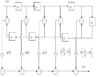
For N even
(13)
The output transform
(14)
Here N/2 multipliers are required [10].
Fig 4 Linear phase structure of FIR Filter when N is even
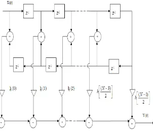
For N odd,
© IJERGS, All Rights Reserved.
Pag
e
127
Pag
e
127
Pag
e
127
Pag
e
127
Pag
e
127
Pag
e
127
Pag
e
127
Pag
e
127
Pag
e
127
Pag
e
127
Pag
e
127
Pag
e
127
Pag
e
127
Pag
e
127
Pag
e
127
Pag
e
127
Pag
e
127
Pag
e
127
Pag
e
127
Pag
e
127
Pag
e
127
Fig 5 Linear phase structure of FIR Filter when N is odd
The linear phase FIR system recognition require approximately only half the number of multipliers than direct form and
cascade form realizations [12]. The samples obtained by sampling ideal frequency response are DFT coefficients. The
complex DFT coefficients obtain by sampling frequency response always exist as conjugate pairs [13].
Fig 6 Block Diagram of Implementation of Linear Phase FIR Filter
Algorithm:
1. We calculate the coefficients with the help of following formula
© IJERGS, All Rights Reserved.
Pag
e
128
Pag
e
128
Pag
e
128
Pag
e
128
Pag
e
128
Pag
e
128
Pag
e
128
Pag
e
128
Pag
e
128
Pag
e
128
Pag
e
128
Pag
e
128
Pag
e
128
Pag
e
128
Pag
e
128
Pag
e
128
Pag
e
128
Pag
e
128
Pag
e
128
Pag
e
128
Pag
e
128
2. In VHDL implementation, find the output Y(z) of proposed design of linear phase FIR filter .
a) We separate the inputs into 1st stage and 2nd stage.
b) Now add the first input of first stage with last input of second stage and then increase the input of first stage and decrease the input of second stage. L = Q1 + Q10
c) Now multiply the result of above addition with coefficients.
d) Now add all the multiplicands to find the output.
3. Now frequency response generated by using MATLAB.
Result
Fig. 7: Graphical Comparison of Area
© IJERGS, All Rights Reserved.
Pag
e
129
Pag
e
129
Pag
e
129
Pag
e
129
Pag
e
129
Pag
e
129
Pag
e
129
Pag
e
129
Pag
e
129
Pag
e
129
Pag
e
129
Pag
e
129
Pag
e
129
Pag
e
129
Pag
e
129
Pag
e
129
Pag
e
129
Pag
e
129
Pag
e
129
Pag
e
129
Pag
e
129
Fig. 9: Graphical Comparison of Power
Fig. 10: Graphical Comparison of Delay*Power
© IJERGS, All Rights Reserved.
Pag
e
130
Pag
e
130
Pag
e
130
Pag
e
130
Pag
e
130
Pag
e
130
Pag
e
130
Pag
e
130
Pag
e
130
Pag
e
130
Pag
e
130
Pag
e
130
Pag
e
130
Pag
e
130
Pag
e
130
Pag
e
130
Pag
e
130
Pag
e
130
Pag
e
130
Pag
e
130
Pag
e
130
Conclusion
Table 1 shows the Overall Comparison of Basic FIR, Cascade FIR and Linear Phase FIR Filters Design. It is clear that
there is a decrease in circuitry, power consumption of Cascade FIR as compared to the Linear Phase FIR design But an
increase in time consumption of Cascade FIR as compared to the Linear Phase FIR design. The overall product of delay
(ns) and power (mW) of Linear Phase Fitler is reduced by 42.79% as compared to Cascade Filter, which shows the
improvement in Linear Phase FIR Filter Design results.
References
1. “A low-power digit-based reconfigurable FIR filter”, K.-H. Chen and T.-D. Chiueh, IEEE Transaction Circuits Syst.
II, vol. 53, no. 8, pp. 617–621, August 2006.
2. “The multiplexed structure of multi-channel FIR filter and itsresources evaluation”, L. Ming and Y.
Chao,inProc. Int.Conference . CDCIEM, pp. 764–768, Mar. 2012.
3. “Reconfigurable architecture of a RRC FIR interpolator for multi-standard digital up converter”, Hatai, I.
Chakrabarti, and S. Banerjee, in Proc. IEEE 27th IPDPSW, pp. 247–251, May 2013.
4. “FPGA realization of FIR filters by efficient and flexible systolization using distributed arithmetic”, P. K. Meher, S.
Chandrasekaran, and A. Amira, IEEE Trans. Signal Process., vol. 56, no. 7, pp. 3009–3017, July. 2008.
5. “Dynamically reconfigurable FIR filter architectures with fast reconfiguration”, M. Kumm, Moller, and P. Zipf, in
Proc. 8th Int. Workshop ReCoSoC, pp. 1–8, Jul. 2013.
6. “High-throughput pipelined realization of adaptive FIR filter based ondistributed arithmetic”, P. K. Meher and
S. Y. Park, in Proc.IEEE/IFIP 19th Int. Conf. VLSI-SOC, pp. 428–433, Oct. 2011.
7. “Adaptive filters using modified sliding-block distributed arithmetic with offset binary coding”, W. Huang and D. V.
Anderson, in Proc. IEEE In. Conf. Acoust., Speech, Signal Process. (ICASSP), pp. 545– 548, 2009.
8. “Delayed block LMS algorithm and concurrent architecture forhigh-speed implementation of adaptive FIR filters”,
B. K. Mohanty and K. Meher, presented at the IEEE Region 10 TENCON 2008 Conf., Hyderabad, India, Nov. 2008
9. “Two high-performance adaptive filter implementation schemes using distributed arithmetic”, R. Guo and L. S.
DeBrunner, IEEE Trans. Circuits Syst. II, vol. 58, no. 9, pp. 600–604, September 2011.
10. “FPGA implementation of fast block LMS adaptive filter using distributed arithmetic for high-throughput”, S.
Baghel and R. Shaik, in Proc. Int. Conference. Commun. Signal Process. (ICCSP), pp. 443– 447, Feb. 10–12, 2011.
11. “Low power and less complex implementation of fast block LMS adaptive filter using distributed arithmetic”,
Baghel and R. Shaik, in Proc. IEEE Students Technol. Symp., pp. 214–219, January 14–16, 2011.
12. “Design and realization of FIR digital filters based on MATLAB”Chonghua Li, IEEE Anti-Counterfeiting Security
and Identification in Communication (ASID), 2010 International Conference, ISBN no. 978-1-4244-6731-0, pp. 101 –
104, 18-20 July 2010.
13. “Design of Digit-Serial FIR Filters: Algorithms, Architectures, and a CAD Tool”, Aksoy L., Lazzari C., Costa E.,
© IJERGS, All Rights Reserved.
Pag
e
131
Pag
e
131
Pag
e
131
Pag
e
131
Pag
e
131
Pag
e
131
Pag
e
131
Pag
e
131
Pag
e
131
Pag
e
131
Pag
e
131
Pag
e
131
Pag
e
131
Pag
e
131
Pag
e
131
Pag
e
131
Pag
e
131
Pag
e
131
Pag
e
131
Pag
e
131
Pag
e
131
Mandal D. and MondalS., Research and Development (SCOReD), 2011 IEEE Student Conference, ISBN no.