3D NUMERICAL INVESTIGATION ON LAMINAR FORCED
CONVECTION AND HEAT TRANSFER IN A CIRCULAR TUBE
INSERTED WITH RIGHT TRIANGULAR WAVY SURFACES
Withada Jedsadaratanachai
aand Amnart Boonloi
b,*a Department of Mechanical Engineering, Faculty of Engineering, King Mongkut’s Institute of Technology Ladkrabang, Bangkok 10520, Thailand b Department of Mechanical Engineering Technology, College of Industrial Technology, King Mongkut’s University of Technology North Bangkok,
Bangkok 10800, Thailand
A
BSTRACTNumerical investigations on flow and heat transfer characteristics in a circular tube heat exchanger inserted with right triangular wavy surfaces are reported. The configurations of the wavy surfaces; incline and V-shape, are studied with flow attack angles of 30o, 45o and 60o for the Reynolds
numbers, Re = 100 – 2000. The numerical results are compared with the smooth circular tube. The mechanisms on flow and heat transfer in the tube heat exchanger with the wavy surface are presented. As the results, the wavy surface can generate the vortex flow and impinging flow through the test section that helps to improve the heat transfer rate and thermal performance. The impingement of the flow on the tube wall disturbs the thermal boundary layer that is an important factor to enhance the heat transfer rate. The V-Downstream wavy surface can create the highest strength of the impinging flow that leads to the highest heat transfer rate. In the range investigate, the augmentations are around 1.2 – 7.6 and 4 – 43.6 times above the smooth tube for the heat transfer and friction loss, respectively. In addition, the optimum thermal enhancement factor, TEF, is around 2.42 for the V-Downstream wavy surface at α = 30o and Re = 2000.
Keywords: flow structure, heat exchanger, heat transfer, thermal performance, right triangular wavy surface.
* Corresponding author. Email:[email protected]
1.
INTRODUCTION
Heat exchanger is an important equipment in many industries; chemical industry, food industry, automotive industry, etc. The improvement of the heat exchanger can help to save cost and energy for the manufacturing process. The enhancement of the thermal performance in the heat exchanger is always done by using the passive method. The concept of the passive method is to generate the vortex flow, impinging flow and disturbing the thermal boundary layer by the vortex generators (not require the addition power into the heat exchanger). There are many types of the vortex generators such as rib, baffle, fin, winglet, roughness surface. The selection of the vortex generators depends on the application of the heat exchanger.
Many researchers reported numerical and experimental studies on flow structures and heat transfer characteristics in heat exchangers with wavy surfaces. Numerical investigations on flow and heat transfer profiles of smooth wavy fin-and-elliptical tube heat exchanger with vortex generators were presented by Lofti et al. (2014). The rectangular trapezoidal winglet (RTW), angle rectangular winglet (ARW), curved angle rectangular winglet (CARW) and wheeler wishbone (WW) were selected to augment the heat transfer rate and performance in the heat exchanger. They pointed out that the CARW gives the best thermal performance at small attack angle of the winglet, while the RTW performs the optimum performance at high flow attack angle. Dong et al. (2013) improved fin-and-flat tube heat exchanger with wavy surface. They claimed that the amplitude of the wavy surface is an important factor to enhance the performance of the heat exchanger. Dong et al. (2010) investigated on mechanisms of flow and heat transfer in wavy fin-and-flat
tube heat exchanger by both numerical and experimental methods. They concluded that the wavy amplitude is a key for the heat transfer augmentation, while the shape of the wavy surface has a few effect on the performance improvement. The heat transfer, pressure loss and thermo-hydraulic performance in fin-and-tube heat exchanger with wavy rectangular winglet vortex generators were studied by Gholami et al. (2014). They found that the wavy rectangular winglet vortex generators improve the heat transfer rate in the heat exchanger with a moderate pressure loss penalty. Gong et al. (2013) and Du et al. (2014) numerically studied on flow and heat transfer behaviors in wavy fin-and-tube heat exchanger with combined longitudinal vortex generators. The experimental investigation on thermo-hydraulic performance in wavy fin-and-tube heat exchanger with combined longitudinal vortex generators was also reported by Du et al. (2013). Ahmed et al. (2015) numerically investigated on heat transfer augmentation in a wavy channel. They summarized that the amplitude of the wavy channel has directly effect for the augmentations on heat transfer rate and pressure loss. Sui et al. (2014) experimentally investigated on flow configuration and heat transfer characteristic in wavy microchannels. They found that the wavy microchannel provides higher thermal efficiency than the baseline channel. Abhishek et al. (2014) presented 3D numerical investigations on turbulent flow and heat transfer in a wavy-walled duct. The enhancement on heat transfer rate in a channel with V-shaped wavy lower plate was reported by Abed et al. (2015). They said that the V-shaped wavy channel has advantage for using nanofluid. Yang et al. (2013) numerically studied the heat transfer enhancement in a wavy channel. The influences of the wavy amplitude and the wavy number were presented.
Frontiers in Heat and Mass Transfer
As above, the wavy surface is applied on the fin plate in the fin-and-tube heat exchanger and on the channel wall to improve the thermal performance and heat transfer rate. The use of the wavy surface as the vortex generators inserted in the tube heat exchanger has rarely been reported. Therefore, in the present work, the right triangular wavy surfaces with various shapes; inclined and V-shaped wavy surfaces, are inserted in the middle of the circular tube heat exchanger to create the vortex flow and to disturb the thermal boundary layer. The disturbance of the thermal boundary layer may lead to an augmentation on heat transfer and thermal performance. The inclined and V-shaped wavy surfaces are selected due to the investigations from the Refs. (Promvonge et al. (2011), Singh et al. (2012), Hans et al. (2011), Singh et al. (2011), SriHarsha et al. (2009), Karwa and Chauhan (2010), Tang and Zhu (2013), Peng et al. (2011)). For a better understanding of the mechanisms in the tube heat exchanger, the numerical method is selected to solve the present problem. The effects of the flow attack angle and V-shaped arrangement are described.
2.
COMPUTATIONAL DOMAIN AND TUBE
CONFIGURATION
The three types of the wavy surfaces are inserted in the middle of the circular tube heat exchanger. The amplitude of the wavy surface is defined as e/D = 0.1. The angle of the wavy surface,θ, is equal to 45o.
The influences of the flow attack angles; α = 30o, 45o, 60o, on flow and
heat transfer are investigated of the Reynolds numbers, Re = 100 – 1200. The V-Downstream and V-Upstream of the V-shaped wavy surfaces are compared.
(a)
(b)
(c)
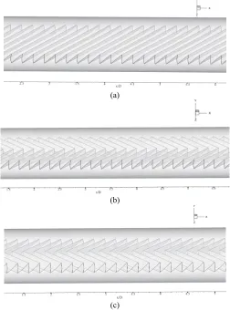
Fig. 1 The tube heat exchanger inserted with (a) Inclined wavy surface, (b) V-Downstream wavy surface and (c) V-Upstream wavy surface.
The numerical results are also compared with the smooth tube with no wavy surface. The inclined, V-Downstream and V-Upstream wavy
surfaces in the circular tube heat exchanger are presented in the Figs. 1a, b and c, respectively, while the parameters of the wavy surface are depicted as the Fig. 2. Figs. 3a, b and c present the computational domain of the circular tube heat exchanger inserted with the inclined, V-Downstream and V-Upstream wavy surfaces, respectively.
Fig. 2 Parameter of the wavy surface.
(a)
(b) (c)
Fig. 3 Computational domain of the circular tube heat exchanger with (a) inclined wavy surface, (b) V-Downstream wavy surface and (d) V-Upstream wavy surface.
3.
ASSUMPTION AND BOUNDARY
CONDITION
The boundary conditions for the current computational domain are presented in Table 1.
The current investigations on both flow configuration and heat transfer behavior are developed under following assumptions:
Steady three–dimensional fluid flow and heat transfer. The flow is laminar and incompressible.
Constant fluid properties.
Body forces and viscous dissipation are ignored. Negligible radiation heat transfer and natural convection.
Table 1 The boundary condition for the current computational domain.
Zone Boundary condition
Inlet, outlet Periodic condition
Tube wall Constant temperature at 310 K
Tested fluid - Constant mass flow rate of the air at 300 K - Constant properties at the average temperature
Wavy surface Adiabatic wall condition
4.
MATHEMATICAL FOUNDATION
Based on the above assumptions, the flow in circular tube is governed by the continuity, the Navier–Stokes and the energy equations. In the Cartesian tensor system these equations can be written as follows:( )
i 0i
u x
ρ
∂ =
∂ (1)
Momentum equation:
(
i j)
i jj i j j i
u u P u u
x x x x x
ρ
μ
∂ ∂ ∂ ∂ ∂
= − + +
∂ ∂ ∂ ∂ ∂ (2)
Energy equation:
(
i)
i j j
u T T
x x x
ρ
∂ = ∂ Γ∂
∂ ∂ ∂ (3)
where, Γ is the thermal diffusivity and is given by
Pr
μ
Γ = (4)
Apart from the energy equation discretize by the QUICK scheme, the governing equations are discretized by the second order upwind (SOU) scheme, decoupling with the SIMPLE algorithm, and solved by using a finite volume approach. The solutions are considered to be converged when the normalized residual values are less than 10−5 for all
variables, but less than 10−9 only for the energy equation.
Four parameters of interest in the present work are the Reynolds number, friction factor, Nusselt number and thermal enhancement factor. The Reynolds number is defined as
uD Re
ρ
μ
= (5)
The friction factor, f is computed by pressure drop, Δp, across the length of the periodic tube, L, as
(
)
2
1 2
P / L D f
u
ρ Δ
= (6)
The heat transfer is measured by the local Nusselt number which can be written as
x x
h D Nu
k
= (7)
The average Nusselt number can be obtained by 1
x
Nu Nu A A
=
∂ (8)The thermal enhancement factor (TEF) is defined as the ratio of the heat transfer coefficient of an augmented surface, h to that of a smooth surface, h0, at an equal pumping power and given by
(
) (
)
1 30 0
0 0
/
pp pp
h Nu
TEF Nu / Nu f / f
h Nu
= = = (9)
where Nu0 and f0 stand for Nusselt number and friction factor for
the smooth tube, respectively.
5.
NUMERICAL RESULT
Numerical results on flow and heat transfer in the tube heat exchanger with wavy surfaces are divided into four topics; validation of the smooth tube and grid independence, flow topology, heat transfer behavior and performance assessment. The mathematical model is validated to assure that the model provides high accuracy and precision results. The flow and heat transfer characteristics in the tube heat exchanger are reported to help to describe the mechanisms in the tested tube. The performance assessment is also presented in terms of the Nusselt number ratio (Nu/Nu0), friction factor ratio (f/f0) and thermal enhancement factor (TEF)
with the Reynolds number.
5.1 Validation of the smooth tube and grid independence
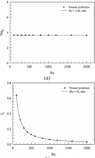
The validations with the smooth tube are done by compared the present results with the values from the correlations on the Nusselt number and friction factor. The results are found in excellent agreement within ±0.03% and ±0.05%, respectively, for the Nusselt number and frictionfactor. Figs. 4a and b illustrate the validations of the smooth circular tube with no wavy surface for the Nusselt number and friction factor, respectively.
The grid independence is tested in the present computational domain. The numbers of grid cells around 80000, 120000, 160000, 240000 and 300000 are compared on the heat transfer and friction loss. It is found that the rise of grid cell from 160000 to 240000 has no effect on both the Nusselt number and friction factor. Therefore, the grid cells around 160000 are selected in all cases of the present investigation.
(a)
(b)
Fig. 4 Validations of the smooth circular tube for (a) Nusselt number and (b) friction factor.
5.2 Flow topology
The flow structures in the tube heat exchanger with the wavy surfaces are reported in terms of tangential velocity vector in transverse planes, streamlines in transverse planes and streamlines in three dimensions. The flow topologies can help to describe the mechanisms in the tube heat exchanger that is a way to improve the thermal performance of the heat exchangers.
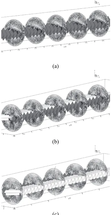
Figs. 5a, b and c present the tangential velocity in transverse planes for the tube heat exchanger with inclined, Downstream and V-Upstream wavy surfaces, respectively, with the flow attack angle of 45o
and Re = 1000. In general, the wavy surfaces can generate the vortex flows through the test sections in all cases. The inclined wavy surface creates two vortex flows at the upper and lower parts of the plane, while the V-Downstream and V-Upstream wavy surfaces promote four main vortex flows. At the lower part of the plane, the counter rotating flows with common-flow-down and common-flow-up are found in the wavy surfaces with V-Downstream and V-Upstream, respectively. The streamlines in transverse planes with various x/D values of the inclined, V-Downstream and V-Upstream wavy surfaces are reported in the Fig. 6. Fig. 7a displays the streamlines impinging on the tube wall of the tube heat exchanger inserted with the inclined wavy surface at α = 45o
(a)
(b)
(c)
Fig. 5 Tangential velocity vectors in transverse planes for (a) Inclined wavy surface, (b) Downstream wavy surface and (c) V-Upstream wavy surface at α = 45o and Re = 1000.
Fig. 7b reports the impinging jets on the tube wall with the local Nusselt number distributions for the V-Downstream wavy surface at α = 45o and Re = 1000. The flow impinges on the left-right parts of the tube,
and then slides on the groove of the wavy surface before flows up to the upper part of the tube wall and impinges there. The impingement flow on the upper part of the tube is found stronger than the left-right parts of the tube, therefore, the peak of heat transfer rate is found at the upper area of the test tube.
Fig. 6 Streamlines in transverse planes with various x/D values for
Inclined, V-Downstream and V-Upstream wavy surfaces at α = 45o and Re = 1000.
Fig. 7c illustrates the impingement flow on the tube wall for the V-Upstream wavy surface with the local Nusselt number distributions at α = 45o and Re = 1000. The flow impinges on the V-tip of the wavy surface
and slides on the groove of the wavy surface before bounces on the left-right parts of the tube wall. The highest heat transfer regime is due to the impingement flow on the tube wall. In addition, the impinging flow disturbs the thermal boundary layer on the tube wall that helps to augment the heat transfer rate and thermal performance in the heating system.
(a)
(b)
(c)
Fig. 7 Streamlines impinging on the tube wall for (a) Inclined wavy surface, (b) V-Downstream wavy surface and (c) V-Upstream wavy surface at α = 45o and Re = 1000.
5.3 Heat transfer behavior
Figs. 8a, b and c present the temperature distributions in transverse planes for the tube heat exchanger with the inclined, V-Downstreamwavy surfaces at α = 45o and Re = 1000, respectively. In general, the blue
contour (low temperature) is found at the core of the tube, while the red contour (high temperature) is found near the wall regime. The vortex flow and impinging flow help to improve the fluid mixing between near the wall and the core of the test tube. The disturbance of the thermal boundary layer is found at the upper part of the plane for the V-Upstream wavy surface.
Figs. 9a, b and c report the local Nusselt number distributions on the tube wall of the tube heat exchanger inserted with inclined, V-Downstream and V-Upstream wavy surfaces, respectively, at α = 45o and
Re = 1000. Generally, the best heat transfer region is found at the upper part of the test tube in all cases. The inclined and V-Upstream wavy surfaces perform the peak of heat transfer regime at the upper left-right parts, while the V-Downstream wavy surface gives the best heat transfer rate at the upper zone of the tube heat exchanger. The V-Downstream wavy surface provides the largest area of red contour. This means that the V-Downstream wavy surface can generate the optimum strength of the impinging flow that results in the highest heat transfer rate.
(a)
(b)
(c)
Fig. 8 Temperature distributions in transverse planes for (a) Inclined wavy surface, (b) Downstream wavy surface and (c) V-Upstream wavy surface at α = 45o and Re = 1000.
(a)
(b)
(c)
Fig. 9 Local Nusselt number distributions on the tube wall for (a)
Inclined wavy surface, (b) V-Downstream wavy surface and (c) V-Upstream wavy surface at α = 45o and Re = 1000.
5.4 Performance assessment
The performance analysis for the tube heat exchanger with various types of wavy surfaces is divided into three parts; heat transfer, friction loss and thermal performance. The heat transfer is reported in term of the Nusselt number ratio, Nu/Nu0, while the friction loss and thermal performance are
presented in forms of the friction factor ratio, f/f0, and thermal
enhancement factor, TEF, respectively.
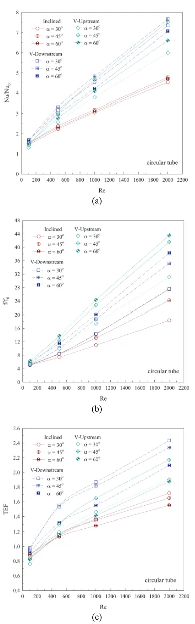
The relation of the Nu/Nu0 with the Reynolds number at various
flow attack angles and types of the wavy surfaces is displayed as Fig. 10a. The Nu/Nu0 tends to increase when increasing Re in all cases. The flow
attack angle of 45o performs the highest heat transfer rate, while the flow
attack angle of 30o gives the reverse trend in all types of the wavy
surfaces. The highest heat transfer rate is around 7.6, 7.5 and 4.7 times above the smooth tube with no wavy surface, respectively, for the V-Downstream, V-Upstream and inclined wavy surfaces at Re = 2000 and α
= 45o. The V-Downstream wavy surface gives the highest heat transfer
due to the highest vortex strength and strongest impinging flow on the tube wall.
The variation of the f/f0 with the Reynolds number at various the
flow attack angles and configurations of the wavy surfaces is reported as Fig. 10b. The use of the wavy surface in the tube heat exchanger not only increases in heat transfer rate, but also increases in the pressure loss. The f/f0 increases with increasing the Reynolds number. The flow attack angle
of 60o performs the highest friction loss, while the flow attack angle of
30o gives the opposite result. The V-Upstream wavy surface provides
respectively, for the V-Upstream, V-Downstream and inclined wavy surfaces at Re = 2000.
(a)
(b)
(c)
Fig. 10 Variations of (a) Nu/Nu0, (b) f/f0 and (c) TEF with the Reynolds
number.
(a) (b)
(c)
Fig. 11 Correlations of the Nu/Nu0 for (a) inclined wavy surface, (b)
V-Downstream wavy surface and (c) V-Upstream wavy surface inserted in the circular tube heat exchanger.
(a) (b)
(b)
(c)
Fig. 12 Correlations of the f/f0 for (a) inclined wavy surface, (b)
Fig. 10c shows the variation of the TEF with the Reynolds number at various cases. The TEF increases with enhancing the Reynolds number for all cases. For V-Downstream and inclined wavy surfaces, the flow attack angle of 30o provides the highest TEF. The flow attack angle of 45o
for the V-Upstream gives the greatest of the TEF in comparison with other angles. The optimum TEF is around 2.42, 2.15 and 1.7 for the V-Downstream, V-Upstream and inclined wavy surfaces, respectively, at Re = 2000. In addition, the flow attack angle of 30o for the V-Downstream
wavy surface can enhance the optimum ratio between the heat transfer rate and pressure loss in the heating system.
6.
CONCLUSION
Numerical investigations on flow configurations and heat transfer characteristics in the tube heat exchanger inserted with various types of the right triangular wavy surfaces; inclined, Downstream and V-Upstream wavy surfaces, are performed. The numerical results are reported in terms of the mechanisms (on both flow and heat transfer structures) and performance evaluations. The results are compared to the smooth tube with no wavy surface. The main findings are concluded as follows;
The wavy surface generates the vortex flow and impingement flow through the test section in all cases. The impinging flow on the tube wall disturbs the thermal boundary layer that results in the rise of the heat transfer rate and thermal performance. The strength and intensity of the vortex flows are important keys to enhance the heating efficiency.
The V-Downstream wavy surface provides the highest heat transfer rate due to the highest strength of the flow, while the maximum friction loss is found in cases of the V-Upstream wavy surface. In similar configuration, the flow attack angle of 45o performs the highest
heat transfer rate, while the flow attack angle of 60o gives the maximum
pressure loss.
The optimum value of the TEF is found to be around 2.42 for the flow attack angle of 30o of the V-Downstream wavy surface at Re =
2000. In the range investigate, the use of the wavy surface gives the heat transfer rate and friction loss around 1.2 – 7.6 and 4 – 43.6 times above the smooth circular tube, respectively.
Figs. 11a, b and c report the correlations of the Nu/Nu0 for the
inclined, V-Downstream and V-Upstream wavy surfaces inserted in the middle of the circular tube heat exchanger, respectively, while the correlations of the f/f0 are presented as Figs. 12. The correlations of the
Nu/Nu0 and f/f0 for the circular tube heat exchanger inserted with
various types of the wavy surfaces are presented as equations 11-16. The deviations between the present values and the values from the correlations are within ±10%.
0 366 0 4 0 058 0 0 244 . . .
Nu / Nu = . Re Pr α , inclined wavy surface (11)
0 482 0 4 0 044 0 0 233 . . .
Nu / Nu = . Re Pr α− , V-Downstream wavy surface (12)
0 506 0 4 0 161 0 0 082 . . .
Nu / Nu = . Re Pr α , V-Upstream wavy surface (13)
0 483 0 308 0 0 154 . .
f / f = . Re α , inclined wavy surface (14)
0 589 0 413 0 0 068 . .
f / f = . Re α , V-Downstream wavy surface (15)
0 633 0 432 0 0 054 . .
f / f = . Re α , V-Upstream wavy surface (16)
for α = 30o, 45o and 60o, Re = 100 – 1200.
ACKNOWLEDGEMENTS
This research was funded by College of Industrial Technology, King Mongkut’s University of Technology North Bangkok (Grant No. Res-CIT0208/2017). The authors would like to thank Assoc. Prof. Dr. Pongjet Promvonge, KMITL for suggestions.
NOMENCLATURE
e amplitude of the wavy surface, m D diameter of a circular tube
f friction factor
GCI grid convergence index
h convective heat transfer coefficient, W m-2 K-1
k thermal conductivity, W m-1 K-1
Nu Nusselt number p static pressure, Pa Pr Prandtl number Re Reynolds number, T temperature, K ui velocity in xi-direction, m s-1
Greek letter
µ dynamic viscosity, kg s-1m-1
Γ thermal diffusivity
α flow attack angle, degree
TEF thermal enhancement factor, (=(Nu/Nu0)/(f/f0)1/3)
ρ density, kg m-3
θ wavy surface angle, degree Subscript
in inlet
0 smooth tube
w wall
pp pumping power
REFERENCES
Abed, A.M., Sopian, K., Mohammed, H.A., Alghoul, M.A., Ruslan, M.H., Mat, S., and Al-Shamani, A.N., 2015, “Enhance Heat Transfer in the Channel with V-shaped Wavy Lower Plate Using Liquid Nanofluids,” Case Studies in Thermal Engineering, 5, 13-23. http://dx.doi.org/10.1016/j.csite.2014.11.001
Dong, J., Chen, J., Zhang, W., and Hu, J., 2010, “Experimental and Numerical Investigation of Thermal-hydraulic Performance in Wavy Fin-and-flat Tube Heat Exchangers,” Applied Thermal Engineering, 30(11-12), 1377 - 1386.
https://doi.org/10.1016/j.applthermaleng.2010.02.027
Dong, J., Su, L., Chen, Q., and Xu, W., 2013, “Experimental Study on Thermal–hydraulic Performance of a Wavy Fin-and-flat Tube Aluminum Heat Exchanger,” Applied Thermal Engineering, 51(1-2), 32-39.
https://doi.org/10.1016/j.applthermaleng.2012.09.018
Du, X., Feng, L., Li, L., Yang, L., and Yang, Y., 2014, “Heat Transfer Enhancement of Wavy Finned Flat Tube by Punched Longitudinal Vortex Generators,” International Journal of Heat and Mass Transfer, 75, 368-380.
https://doi.org/10.1016/j.ijheatmasstransfer.2014.03.081
Du, X., Feng, L., Yang, Y., and Yang, L., 2013, “Experimental Study on Heat Transfer Enhancement of Wavy finned Flat Tube with Longitudinal Vortex Generators,” Applied Thermal Engineering, 50(1), 55-62.
https://doi.org/10.1016/j.applthermaleng.2012.05.024
Gholami, A.A., Wahid, M.A., and Mohammed, H.A., 2014, “Heat Transfer Enhancement and Pressure Drop for Fin-and-tube Compact Heat Exchangers with Wavy Rectangular Winglet-type Vortex Generators,” International Communications in Heat and Mass Transfer, 54, 132-140.
https://doi.org/10.1016/j.icheatmasstransfer.2014.02.016
Hans, V.S., Saini, R.P., and Saini, J.S., 2010, “Heat Transfer and Friction Factor Correlations for A Solar Air Heater Duct Roughened Artificially with Multiple V-ribs,” Solar Energy, 84(6), 898-911. https://doi.org/10.1016/j.solener.2010.02.004
Jedsadaratanachai W., and Boonloi, A., 2014, “Effects of Blockage Ratio and Pitch Ratio on Thermal Performance in A Square Channel with 30° Double V-baffles,” Case Studies in Thermal Engineering, 4, 118-128.
https://doi.org/10.1016/j.csite.2014.08.002
Karwa, R., and Chauhan, K., 2010, “Performance Evaluation of Solar Air Heaters Having V-down Discrete Rib Roughness on the Absorber Plate,” Energy, 35(1), 398-409.
https://doi.org/10.1016/j.energy.2009.10.007
Karwa, R., and Chitoshiya, G., 2013, “Performance Study of Solar Air Heater Having V-down Discrete Ribs on Absorber Plate,” Energy, 55, 939-955.
https://doi.org/10.1016/j.energy.2013.03.068
Lotfi, B., Zeng, M., Sundén, B., and Wang, Q., 2014, “3D Numerical Investigation of Flow and Heat Transfer Characteristics in Smooth Wavy Fin-and-elliptical Tube Heat Exchangers Using New Type Vortex Generators,” Energy, 73, 233-257.
https://doi.org/10.1016/j.energy.2014.06.016
Peng, W., Jiang, P.X., Wang, Y.P., and Wei, B.Y., 2011, “Experimental and Numerical Investigation of Convection Heat Transfer in Channels with Different Types of Ribs,” Applied Thermal Engineering, 31(14-15), 2702-2708.
10.1016/j.applthermaleng.2011.04.040
Promvonge, P., Changcharoen, W., Kwankaomeng, S., and Thianpong, C., 2011, “Numerical Heat Transfer Study of Turbulent Square-duct Flow Through Inline V-shaped Discrete Ribs,” International Communications in Heat and Mass Transfer, 38(10), 1392-1399. https://doi.org/10.1016/j.icheatmasstransfer.2011.07.014
Singh, S., Chander, S., and Saini, J.S., 2011, “Heat Transfer and Friction Factor Correlations of Solar Air Heater Ducts Artificially Roughened with Discrete V-down Ribs,” Energy, 36(8), 5053-5064. https://doi.org/10.1016/j.energy.2011.05.052
Singh, S., Chander, S., and Saini, J.S., 2012, “Investigations on Thermo-hydraulic Performance due to Flow-attack-angle in V-down Rib with Gap in a Rectangular Duct of Solar Air Heater,” Applied Energy, 97, 907-912.
https://doi.org/10.1016/j.apenergy.2011.11.090
Singh, S., Chander, S., and Saini, J.S., 2015, “Thermo-hydraulic Performance due to Relative Roughness Pitch in V-down Rib with Gap in Solar Air Heater Duct-Comparison with Similar Rib Roughness Geometries,” Renewable and Sustainable Energy Reviews, 43, 1159-1166.
https://doi.org/10.1016/j.rser.2014.11.087
SriHarsha, V., Prabhu, S.V., and Vedula, R.P., 2009, “Influence of Rib Height on the Local Heat Transfer Distribution and Pressure Drop in A Square Channel with 90o Continuous and 60o V-broken Ribs,” Applied
Thermal Engineering, 29(11-12), 2444-2459. https://doi.org/10.1016/j.applthermaleng.2008.12.015
Tang, X.Y., and Zhu, D.S., 2013, “Flow Structure and Heat Transfer in a Narrow Rectangular Channel with Different Discrete Rib Arrays,” Chemical Engineering and Processing: Process Intensification, 69, 1-14.
https://doi.org/10.1016/j.cep.2013.01.005
Yang, Y.T., Wang, Y.H., and Tseng, P.K., 2014, “Numerical Optimization of Heat Transfer Enhancement in A Wavy Channel Using Nanofluids,” International Communications in Heat and Mass Transfer, 51, 9-17.