INTRODUCTION
At present, the topic of cost savings is very relevant. In automotive production, repair of faults and the production of non-distributors are very expensive. Therefore, more and more sys-tems are being used to prevent the production of non-products, faulty products and, in particu-lar, to detect errors directly at their source. One of these systems is also the Pick to Light system which has a wide application in manufacturing, assembly and logistics.
The work is devoted to PLC automation programming. The principle of PLC automa-tion is explained and a simple example de-scribes the program writing methodology. The work also contains a detailed procedure for backing up and recording the program into the PLC which allows the program to con-tinue working, editing and testing. The paper briefly describes the programs needed to edit the program in the PLC, the HMI panel screen and a virtual model of the Lean Laboratory
which allows the program to be tested with-out connecting to the PLC or HMI panel itself. Lean Manufacturing is a systematic approach to identifying and preventing wastage (limiting the performance of value-added activities) by continually improving the production processes. Systematically eliminating sources of waste re-duces the production costs. At the same time, it is necessary to remember the customer require-ments and also to increase the added value of the production process.
However, in some cases, the customer’s re-quirements necessitate certain wastage which should be highlighted and the excess costs associ-ated with this waste may be taken into account in the end product price.
Waste is the opposite of added value. This statement includes all the activities that the cus-tomer does not want and will not pay for. For ex-ample, the customer is willing to pay for sheet metal, sheet metal bending, welding, surface treat-ment, and so. However, he is not willing to pay for waiting time, repairs, surplus stocks, and so on.
Designing and Upgrading the Assembly Process and Verifying
the Performance of the
Pick to Light System
Program
Naqib Daneshjo
1, Albert Mareš
2, Erika Dudaš Pajerská
1, Zuzana Hajduová
11 Faculty of Business Economics with seat in Kosice, University of Economics in Bratislava, Tajovského 13, 04 130, Košice, Slovakia
2 Faculty of Mechanical Engineering, Technical University of Kosice, Letna 19, 040 01, Kosice, Slovakia
* Corresponding author’s e-mail: [email protected]
ABSTRACT
The aim of the work is to change the current program in the programmable logic controller (PLC) to be as close as possible to the real-world Pick to Light system in the automotive industry for installing individual car components. The change consists in completing the navigation and tutorial mode while preserving the original function of the program, which is to measure the time of each step in assembly of the components and the reading of the pieces from the trays. A simple virtual laboratory model was created which enables to test the program even if the access to the PLC and HMI panel is not possible. The partial goal was to modify the visualization of the program in the operator touch panel Human – Machine Interface (HMI). Another partial goal was to implement a new PLC program. In order
to better understand the created program, the flowcharts were created and described for the main parts of the program.
Keywords: PLC system, automotive industry, pick to light system, HMI panel Volume 12, Issue 4, December 2018, pages 126–135
https://doi.org/10.12913/22998624/100346
Research Journal
Accepted: 2018.11.05DESIGNING THE PICK TO LIGHT SYSTEM
PROGRAM
Programmable automaton (PLC) is the most used automation tool in industry. The automation technology has been in use for about 30 years. Programmability close to the mentality of the de-signer is its typical feature. Originally, the PLC was designed for machine control as a substi-tute for fixed relay logic. This also corresponds to the programming language of the contact (relay) schemes.
Programming of PLC
The languages of the first PLCs had several commands (typically 8 or 16) that were equivalent to switching and expanding contact, parallel and serial rack, coils, memory circuits, counters, and timers. Today, there are several types of languag-es available for each programmable machine: ex-cept the language of the contact schema, it is the language of logic schemes, the mnemocode guage or other textual language and also the lan-guage of sequential programming. Contemporary programming languages are considerably richer; unfortunately, the mentality of designers and constructers has come to a halt, so that a “PLC programmer” has become a separate profession. Unification of programming languages and de -velopment systems for PLC is the goal of the new international standard IEC 61131–3.
Programmability and versatility of construc-tion provide the PLC with their versatility and adaptability. It is no longer true that the PLC only solved logical tasks, while specialized control-lers were used to process analog variables. PLC today can handle both types of tasks (and many more). The PLC program can make connections and treat logical connections that are unavailable while using specialized and closed devices. For example, it is possible to solve the links between regulating different variables (for example tem -perature and humidity, tem-perature and burning quality, temperature and compliance) or optimize the process and adapt it to changing conditions, as well as minimize consumption, costs, or losses.
In order to meet the additional requirements, the unchanged PLC configuration is met many times, and increased costs are “only” in program-ming, creating and validating the program (PLC is “software” but it is definitely not free). Numer -ous new features are only implemented during
operations, based on additional user requirements (sometimes they know what is really needed when they are in operation, sometimes they are forced by a change in technology or a changed situation for the user).
It is customary that – in addition to their own control functions – the PLC system is entrusted with analytical functions (error and risk recogni-tion, energy and raw material analysis, production tracking, non-production, loss and deterioration, waste and waste assessment, performance moni-toring and staffing); protection and controls (from unsafe or unwarranted operation of the operator, from any threatening loss or accident). It is clear from the above that today the knowledge on PLC programming is a major advantage for a techni-cian working in the automation industry.
Characteristics of the development environment for programming of PLC
With CX-One software one can build, con-figure and program networks, programmable terminals, PLCs, drives, temperature controllers, sensors and motion control systems. The CX-One environment is based on the application software components such as CX-programmer, de-signer network manager, integrator and CX-server, acting as network-based software applica-tions and application software.
The advantage of such architecture is that us-ers do not have to worry about networks or device drivers while developing their applications. The CX server supports all Omron networks and Om-ron operating systems.
The disadvantage of this software is the fact that the CX-One is paid. This indicates that Om-ron PLCs are designed for industrial use and not for an individual or small business.
CX- One includes these programs: Programming:
• CX- Programmer – PLC automation programming
• CX- Simulator – simulation of automata PLC
• CX- Designer – programming of control terminals
Drives and motion control:
• CX- Motion – for motion control units with analog output
• CX- Position – for PTP motion controls with impulse output
• CX- Motion – MCH – for advanced PTP mo-tion controls with MechatroLinkII
• CX- Drive – for inverters and servo drives Regulation and switching:
• CX- Process Tool – for PLC process units
• CX- Thermotools – for separate temperature controllers
Networks:
• CX- Integrator – industrial networks De-viceNet, Ethernet, Controllerlink, NT-Link, Compoway/F
• CX- Profibus – all Profibus modules [12] PLC programming was linked to the CX-One software packages from CX-programmer, which allows advanced and complex programming. Programming environment CX-programmer is used for programming and subsequent program recording in PLC.
The program can be designed using the fol-lowing programming languages:
• Programming using ladder diagrams LD
• Programming using structured text language ST
The Ladder Diagram (LD) is the most com-mon way of PLC programming by drawing schematics using symbols representing contacts, outputs, wires and a large number of instruc-tions. Each management application written in the CX-Programmer development environment is run as a project. The project may contain sev-eral tasks.
There are two types of tasks: cyclical and interrupting. A cyclic task is executed after run-ning in each PLC cycle until it is paused. One cycle of the interrupting task is always executed by interrupting the program to which the assign-ment is assigned. After it is run, the job stops, the interruption terminates and the program runs cyclically. For easier orientation in a large program, tasks can be further subdivided into arbitrary sections with a freely definable name. The section is as a chapter in the book, and the PLC goes through the sections in the order they are defined in. The sections can be simply re-engineered and copied freely in the program. Each section consists of any number of so-called rungs. It is actually a program line that must al-ways contain at least one contact and at least one output or output instruction.
CX-Programmer programming environment also has the so-called functional blocks – FB. These are predefined programs or features dis
-played as a simple program element containing inputs and outputs. The function block can be de-fined by LD or ST. FB contains inside the defini -tion of variables and the program itself. One al-ready created function block can be used repeat-edly in the form of instances. The user just defines the inputs and outputs. Each instance of FB uses its own allocated memory for its function. FB can be saved in a library and used in another applica-tion. This saves the programmer’s work and scans the written program.
USING OF PROGRAM
The use of the new program is partly ex-plained in the description of the algorithms. However, it is based on the assumption that the user was working with the original program. This manual also describes the operator for non-interested users.
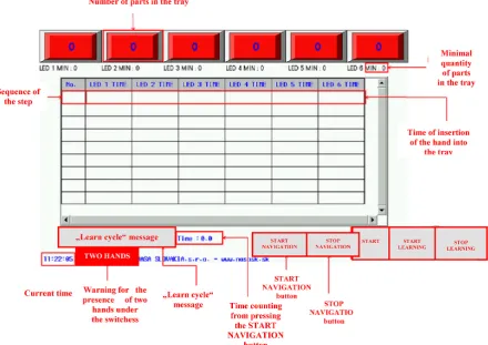
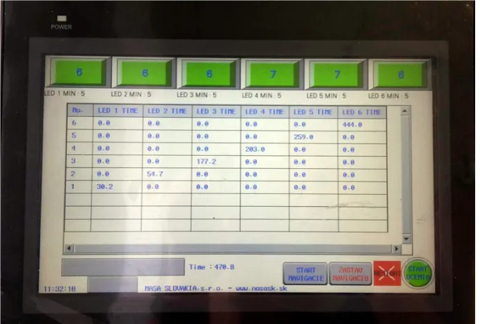
After the PLC is turned on and the program is loaded, the screen shown in Figure 1 is dis-played. The “learn cycle” message is disdis-played. The “two hands” message is not displayed and the STOP LEARNING button is also not dis -played. Sensors, time measurement, countdown and STOP NAVIGATION, START NAVIGA -TION buttons are inactive.
Currently, we can vary the amounts in each field, the minimum quantity limit or press the RESTART and START LEARNING buttons. Pressing the START LEARNING button ac -tivates the sensors. We gradually put our hand into the individual trays. Step saving is indicat-ed by the sensor light. The maximum number of steps learned is nine, the minimum is three steps. After learning three or more steps, the “learn cy-cle” message disappears.
Functions of individual elements / buttons: • 6 red squares – represent the trays under the
sensors, it is possible to edit the number of pieces after clicking on them,
• LED x MIN – limit of the minimum number of parts in the tray, it can be changed at any time,
• Table – times of inserting a hand into individ-ual trays are written and the total sequence of the step for the entire time of the navigation that is being launched, cannot be edited,
• Current time –displays current time, cannot be edited,
• “Learn cycle” message – displayed if the number of stored steps in the PLC is less than 3, cannot be edited,
• Warning „Two hands“ – will appear if two hands are put under two different sensors dur -ing navigation, cannot be edited,
• Time – displays the time counting from press-ing the START NAVIGATION button until the cycle stops, cannot be edited,
• START NAVIGATION – the start button for navigation is only active if three or more steps are stored and the learning mode is not run-ning at the same time,
• STOP NAVIGATION – stop button for
navigation, active if the learning mode is not running,
• RESTART – deleting table data, does not de-lete the sequence learned from PLC, it must be kept for more than a second for security reasons,
• START LEARNING / STOP LEARNING –
the START LEARNING button is used to start the learning mode, after it is pressed to change to the STOP LEARNING button which ends the learned cycle, the buttons are inactive when the navigation is started.
DESIGNING THE ASSEMBLY PROCESS
AND VERIFYING THE PROGRAM
OPERATION
Thanks to this connection, the control unit can accurately determine in which position the lock is currently located. It can evaluate whether the door is closed and if it is closed properly. The lock has a SAFE locking func-tion; it means that cannot be opened from the exterior but not using the inside door handle.
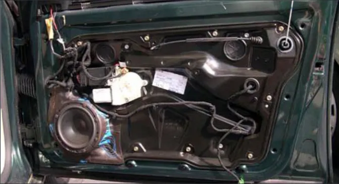
Figure 2 illustrates a door lock fitted by us. Figure 3 shows a view of a door panel in-stalled in the door. The door lock is not visible from this point of view either. Attaching the lock to the door panel and the lock itself is only visible after removing the door panel on the rear panel.
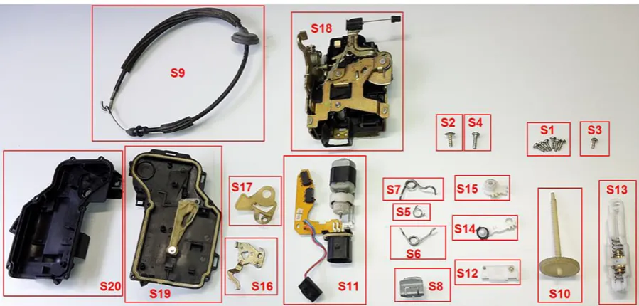
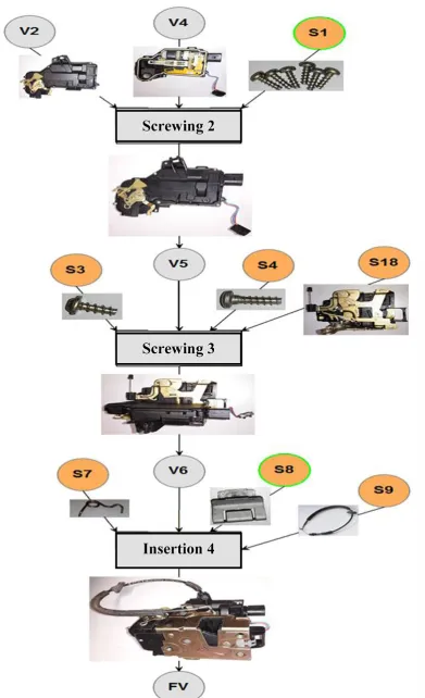
The door lock with marked individual com-ponents can be seen in Figure 4. At first glance, the simple component consists of twenty types of components and twenty-five elements. Decompo -sition of the product is shown in Table 1
Technological process of assembly
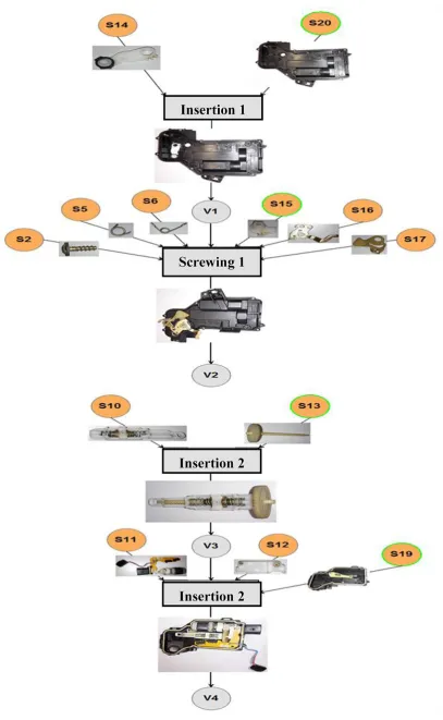
Figure 5 and Figure 6 present the graphs showing the sequence of the door lock assembly. Since the lock consists of twenty kinds of com-ponents but the lab has six sensors, we have tried to select from each operation one component that will be placed under the sensor.
The part located in the container placed under the sensor is in the green ring. In the first opera -tion Inser-tion 1, it is for example component S20 – front cover. The criterion for selecting this com-ponent was to be the basic comcom-ponent from the ones assembled in the operation. The last operation Insertion 4 is exception because it takes only a few seconds, and therefore we can determine the end of assembly of the product according to this part.
Figure 7 is a lay-out of the workplace on which the individual components are placed in
Fig. 2. View of the door panel
the containers. In this figure, we may notice the layout of the workspace from the perspective of the operator. In the upper part of the left is a fin -ished lock and the lock on the right is divided into individual parts.
Realization of assembly with a new program
While installing a lock with a new program, the work layout does not change; it remains the same as in the Figure 8. We can note that thirty seconds have elapsed since the navigation was started until the removal of the component from the cartridge under the number one sensor. The reason for this time difference was the demon -stration of the program’s resistance to the mistake of inserting the hand into the wrong stack. Even though the hand was intentionally inserted into the wrong tray, the program did not write the time of the wrong step. Thus, if we were about
twenty-eight seconds off each step (because otherwise it takes about two seconds to remove the first part) we would obtain approximately the same time of assembly of the entire lock. The reason why the times are basically the same is the fact that the lock is made up of twenty components and the sensors are available at six. In this case, the ben-efit of the new system has not been proven in the shorter time. However, it is fault-tolerant, making it easier to analyze the output data.
The new program is much closer to the prin-ciples of Pick to Light. It can, similarly to the original program, measure the pitch times and subtract from the number of pieces in the individ-ual bins. At the same time, however, the system can learn its own cycle that will be navigated by the operator when installing the component. Even bugs such as inserting both hands into different trays and inserting a hand into the wrong tray are treated in the program.
Fig. 4. Decomposition of door lock with marked parts
Table 1. Decomposition of the product
Title Number of pieces Title Number of pieces
S1 Screw in plastic 3x9 6 S11 Circuit board with motorcycle 1
S2 Screw in plastic 4x13 1 S12 Connection of the motor 1
S3 Screw in plastic 3x7 1 S13 Shaft mechanism 1
S4 Screw in plastic 4x12 1 S14 Motor arm 1
S5 Spring „a“ 1 S15 Wheel of motor arm 1
S6 Spring „b“ 1 S16 Metal molding 1
S7 Spring „c“ 1 S17 Plastic molding 1
S8 Microswitch clip 1 S18 Lock 1
S9 Cord handle rod 1 S19 Back cover 1
S10 Plastic shaft 1 S20 Front cover 1
Figure 7. Suggested layout of the workplace
Figure 8 HMI panel screen after product assembly with new program
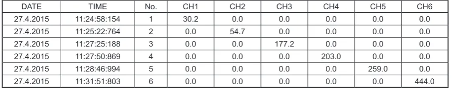
Table 2 Output from the HMI panel on the USB key of the new program
DATE TIME CH0 CH1 CH2 CH3 CH4 CH5 CH6
2015-04-27 11:24:58:154 1 30.200001 0.000000 0.000000 0.000000 0.000000 0.000000
2015-04-27 11:25:22:764 2 0.000000 54.700001 0.000000 0.000000 0.000000 0.000000
2015-04-27 11:27:25:188 3 0.000000 0.000000 177.199997 0.000000 0.000000 0.000000
2015-04-27 11:27:50:869 4 0.000000 0.000000 0.000000 203.000000 0.000000 0.000000
2015-04-27 11:28:46:994 5 0.000000 0.000000 0.000000 0.000000 259.000000 0.000000
Benefits of the new program are as follows:
• This is a full-featured Pick to Light system
• The system is fault-tolerant
• Easier analysis of output data as a result of failure to record faulty steps
• Disadvantages of the new program:
• The greatest disadvantage of the program is the ability to learn a sequence consisting of a maximum of nine steps, due to a small PLC memory
• More complex operation, the same sequence of operations must be followed
• It is not possible to run only time measure-ment without navigation
CONCLUSION
A new PLC program was created, which was the main goal of the contribution. The instructions on how to use the new program and how to imple-ment the program into the PLC were created. The program was tested on the car door component of a door lock. The test also encountered unexpect-ed problems in the theoretical preparation. The new program is functional, but it also has some drawbacks mainly due to the way the program is written and limited PLC memory. In the fu-ture, it would be advisable to try to overwrite the program using text-based text or use functional blocks to save steps and increase the number of steps the system can learn without the need for PLC exchange. Certainly, it would be advisable to add a number of sensors over other trays to get the system closer to the Pick to Light system used to assemble components and products.
In order to compare the outputs of the new and the original program from the HMI panel that were stored on the USB key, it is necessary to ad-just the outputs first. Because it is not possible to choose the format of the data that is saved to the key, it would be appropriate to create an applica-tion capable of converting the output data. This would save time in comparing results.
The selected component, i.e. the door lock, is not ideal for demonstrating a new program. In order to demonstrate time savings, a more conve-nient component with fewer individual elements would be ideal. It is assumed that in such a case, the time difference between the original and the new programs would be more obvious.
Acknowledgements
This work has been supported by the Scien-tific Grant Agency of the Ministry of Education of the Slovak Republic (VEGA 1/0376/17)
REFERENCES
1. Daneshjo N., M, Majernik, E, Danishjoo: More
Exact Approaches to Modernization and Renewal of the Manufacturing Base. TEM Journal. 6(3),
2017, 445–449, DOI: 10.18421/TEM63–03.
2. Daneshjo N., E. Dudaš Pajerská, M. Klimek, E. Dan -ishjoo: Software Support for Optimizing Layout So-lution in Lean Production. TEM Journal. 7(1), 2018,
33–40, DOI: 10.18421/TEM71–05.
3. Dietrich C., N. Daneshjo, M. Danishjoo: Failure
prevention in maintenance services and logistics. Modern Machinery Science Journal, June 2017, Prague, Czech Republic,
4. Fabian M., Ižol P., Draganovská D., Tomáš M. In
-fluence of the CAM parameters and selection of
end-mill cutter when assessing the resultant sur-face quality in 3D milling. Applied Mechanics and
Materials, 474, 2014, 267–272.
5. Ižol P., Fabian M., Kopas M., Fedorko G. Evalua -tion of machining strategies for produc-tion of free form surfaces using 3-axle milling. Manufacturing
Technology, 13(4) 2013, 458–465.
6. Králik M., Jerz V. (2018). The measurement of re -sidual stresses in the surface layers of the materi-als after machining. Materimateri-als Science Forum, 919,
2018, 345–353.
7. Šeminský J. Present trends in designing of tech-nical systems. Applied Mechanics and Materials,
460, 2014, 73–80.
Table 3. Modified output file of the new program from the HMI panel
DATE TIME No. CH1 CH2 CH3 CH4 CH5 CH6
27.4.2015 11:24:58:154 1 30.2 0.0 0.0 0.0 0.0 0.0
27.4.2015 11:25:22:764 2 0.0 54.7 0.0 0.0 0.0 0.0
27.4.2015 11:27:25:188 3 0.0 0.0 177.2 0.0 0.0 0.0
27.4.2015 11:27:50:869 4 0.0 0.0 0.0 203.0 0.0 0.0
27.4.2015 11:28:46:994 5 0.0 0.0 0.0 0.0 259.0 0.0