Please cite this article as: C. Daniel, G. Hemalatha, L. Sarala, D. Tensing, S. Sundar Manoharan, Seismic Mitigation of Building Frames using Magnetorheological Damper, International Journal of Engineering (IJE), IJE TRANSACTIONS B: Applications Vol. 32, No. 11, (November 2019) 1543-1547
International Journal of Engineering
J o u r n a l H o m e p a g e : w w w . i j e . i rSeismic Mitigation of Building Frames using Magnetorheological Damper
C. Daniel*a, G. Hemalathaa, L. Saralaa, D. Tensinga, S. Sundar Manoharanb
a Department of Civil Engineering, Karunya Institute of Technology and Sciences, Coimbatore, India
b Sathyabama Institute of Science and Technology, Chennai, India
P A P E R I N F O
Paper history:
Received 02 August 2019
Received in revised form 06 September 2019 Accepted 12 September 2019
Keywords:
Magnetorheological Damper
Magnetorheological Fluid
Mewmark’s Nonlinear
method
Time History Analysis
A B S T R A C T
The present study focusses on the damping force control of shear mode magnetorheological (MR) damper for seismic mitigations. Therefore, the semi-active MR damper which can control the vibration is analyzed both experimentally and numerically. Carbonyl iron is used as the magnetic particle and Castrol Magnetec oil as carrier fluid throughout the study. MR damper is designed and fabricated, and its damping force was evaluated experimentally at 2.5 A- 10 V. Shear mode MR Damper is tested in universal testing machine using time history loading. The model was numerically analyzed using Newmark’s method for nonlinear system in MATLAB to control the three storey model building frame taken from the literature. The result indicates that 49.42% reduction in displacement at the second storey and 48.14% in the third storey, respectively. Maximum reduction was observed when damper was kept in the ground floor. The maximum force observed for the MR Damper is 0.777 kN.
doi: 10.5829/ije.2019.32.11b.05
1. INTRODUCTION1
In the current scenario, MR damper offers a vital role in controlling building frames, due to its unique features such as mechanical simplicity, less current, more dynamic, more force and more toughness. It impacts mechanical energy to the structural system. Recently, a model of a typical MR damper, based on Bouc–Wen hysteresis model [1] is proposed in connection with the control of responses of structures like building frames and bridges. The proposed model is shown to well represents a wide variety of hysteretic behavior [2-4]. The model significant was elevated in a consequent study in mainly for considering the MR fluid response, additionally shear thickening and thinning properties of the fluid was also studied [5-8]. Various dynamic models with their comprehensive study is optimized [9,10]. MR Damper is the potential vibration control system for seismic mitigation has more advantages than other semi-active control devices [11]. The unique advantage is when increase in input current, the
*Corresponding Author Email: [email protected]
(C. Daniel)
damping force also increased. This energy dissipating device has less power consumption and various dynamic range with simple mechanical designs. The response in structures like reinforce concrete frame has more reduction in displacement compared with the conventional devices [12-15]. Lot of algorithm studies carried out on MR damper for seismic applications but very few experimental investigation was conducted. Present work is a part of hybrid simulation [16, 17]. The input earthquake data is given to the MTS system, which give a response of the MR damper at various time. This output response of MR damper is the input for MATLAB hybrid simulation program under newmarks non-linear analysi where the device placed diagonally and response of each floor of the structure is studied for with and without MR Damper.
2. PREPARATION OF MR FLUID
The carrier oil used in the present work was the commercially available Castrol Magnatec 5W-10. The MR fluid is prepared by mixing the carbonyl iron with
Castrol magnatec oil in the 20:80 ratio by weight is named as MRF 80 where 20% of Carrier oil and 80% of carbonyl magnetic particles. The mixture is stirred at 400 RPM in the overhead stirrer for 24 hours as depicted in Figure 1.
3. SHEAR MODE
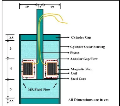
In shear mode, the magnetic field produced is perpendicular to the motion of the moving surfaces as shown in Figure 2. The vibration is controlled when shear form along the annular gap direction in the cylinder inner wall and piston outer wall [18]. For civil engineering concerns, the damper is located in several places and direction, the piston inside the damper produces shear due to the annular gap between piston and inner cylinder is 1-2mm.
4. MR DAMPER
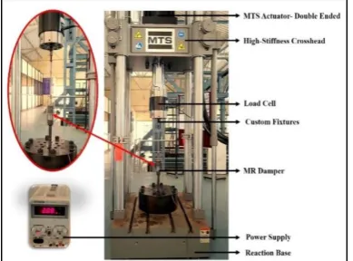
A magnetorheological damper is a type of damper where it contains MR fluid, controlled by an external magnetic field, using an electromagnet [19]. This makes the damping property of the vibration to be controlled by changing the current and voltage of the external electromagnet. The schematic representation of shear mode magnetorheological damper is depicted in Figure 3. The proposed damper has a pay load of 2.28 kg. The fabricated magnetorheological damper is depicted in Figure 4. The MR damper is tested by exciting the damper with the amplitude ±5 mm, current range from 0 – 2.5A and frequency 0.5 Hz using MTS Universal
Figure 1. Schematic representation for preparation of MR
Fluid
Figure 2. Shear mode
Testing machine. This vibration is similar to the cyclic load test. The resulted damping force of the proposed MR damper is measured by a data acquisition system and accelerometer was used to measure movement of the magnetorheological damper. The measured damping force with respect to displacement is represented in Figure 5. The damping force for 0A is 328 N and the maximum damping force at 2.5A is 536 N. The damping force obtained in the test is appropriate for vibration control.
Figure 3. Schematic shear mode Magnetorheological damper
Figure 4. Fabricated Magnetorheological damper
5. DYNAMIC BEHAVIOR OF MR DAMPER
The time history data of El Centro is given for the MR Damper as a input in MTS Universal Testing machine is depicted in Figure 6. The displacement - time and force - time is observed in the experimental investigation of shear mode MR damper shown in Figure 7. The excitation frequency is depending on the ground acceleration data [20, 21]. The coil is wounded with 260 turns of coil and wires are connected to the power supply. The current supplied is 2.5 Amp for MRF 80 fluid configuration and annular gap of 1mm is obtained in the Damper. The displacement is reduced 68.29 % compared to the uncontrolled. The maximum damping force 0.777 kN obtained in Figure 8.
Figure 6. MTS Universal Testing Machine
Figure 7. Displacement vs. Time
Figure 8. Force vs. Time
6. NUMERICAL SOLUTION AND DISCUSSION
From the literature [1] a sample problem was taken to describe the above method which is used mainly to control the vibration response depicted in Figure 9. For 3 dof the building undergoes ground acceleration (El-Centro). Here, K, M, C represents the mass, stiffness and damping matrixes of a certain size in the structure [22]. The structure has n degree of freedom subjected to elcentro earthquake ground acceleration ẍ and f is the control force. The equation of motion is given below:
(1)
x is the displacement, ẋ is the velocity, ẍ is the acceleration, M,C, K are mass , damping coefficient and stiffness in 3*3 matrix form. Γ represents the location of MR Damper (ie. Ground floor, first floor and second floor). For the study MR damper placed in ground floor. Λ is the vector of unity. Newmark's nonlinear integration method using computer programs (MATLAB) to conduct a typical dynamic analysis and flow chart for the analysis is shown in Figure 10.
K= 105 N/m
M = Kg
C = 105 Ns/m
The behavior is obtained using Magnetorheological damper of various features. The efficacy of magnetorheological damper behavior is studied under various parameters. The constraints contain damping force and its location on the structure. In the presence and absence of dampers in ground floor is numerically analyzed in MATLAB. Controlled and uncontrolled response of first, second and third floors are studied with MR dampers, depicting their Displacement-Time characteristics under time history analysis in Figures 10-12. Maximum force and percentage control in each storey is shown in Table 1.
Figure 10. Controlled and uncontrolled response of first floor
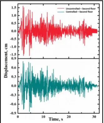
Figure 11. Controlled and uncontrolled response of second
floor
Figure 12. Controlled and uncontrolled response of third floor
TABLE 1. Maximum force and percentage control
Responses measured at
Maximum
Displacement Percentage control
Maximum control force (kN) Uncont
rolled
Contro lled
First storey 0.661 0.339 48.71%
0.777 Second
storey 1.133 0.573 49.42%
Third storey 1.560 0.809 48.14%
7. CONCLUSION
In the present work, a semi-active control of responses for a 3 storey model structure was tested using shear mode magnetorheological damper. force-time results obtained for the magnetorheological damper from the experimental investigation; it can be directly used to develop the control in Newmark’s nonlinear method in MATLAB. Additionally, parametric study is also analyzed to study the influence of the constraints on the behavior of the structure. The experimental test results can be directly incorporated towards the damper position. Significant control of response was achieved with small control force; therefore, with 2.5 A-10 V was used. Position of the damper has made significant note on the effect of control of response. Further, the damper position is also optimized and found lower storey affords the maximum control of response for all storeys. The maximum control force is found to be 0.777 kN. The maximum percentage control of 49.42 % at second storey.
8. ACKNOWLEDGEMENT
The authors thank Department of Science and
Technology (Grant No: DST/TSG/STS/2015/30-G) for their financial support.
9. REFERENCES
1. Dyke, S. J., B. F. Spencer Jr, M. K. Sain, and J. D. Carlson. "Modeling and control of magnetorheological dampers for seismic response reduction", Smart Materials and Structures, Vol. 5, No. 5 (1996), 565.
2. Das, Diptesh, T. K. Datta, and Alok Madan. "Seismic control of building frames using MR damper", In The 14 th World Conference on Earthquake Engineering, (2008) 12-17. 3. Yang, Guangqiang, Billie F. Spencer Jr, Hyung-Jo Jung, and J.
David Carlson. "Dynamic modeling of large-scale magnetorheological damper systems for civil engineering applications", Journal of Engineering Mechanics, Vol. 130, No. 9 (2004), 1107-1114.
5. Djavareshkian, M.H., Esmaeili, A., and Safarzadeh, H., “Optimal Design of Magnetorheological Fluid Damper Based on Response Surface Method”, International Journal of Engineering - Transactions C: Aspects, Vol. 28, No. 9, (2015), 1359–1367
6. Wereley, N. M., J. U. Cho, Y. T. Choi, and S. B. Choi. "Magnetorheological dampers in shear mode" Smart Materials and Structures, Vol. 17, No. 1 (2007), 015022.
7. S. Seid, S. Chandramohan, S. Sujatha, “Design and Evaluation of a Magnetorheological Damper Based Prosthetic Knee”,
International Journal of Engineering, Transactions A: Basics, Vol. 32, No. 1, (2019) 146-152
8. Daniel, C., Ajita Magdalene, G. Hemalatha, and D. Tensing. "Experimental Investigation on Magnetorheological Damper for Seismic Resistance of Structures with Nano Fe3O4 MR Fluid"
International Journal on Applied Bioengineering, Vol. 10, No. 2 (2016).
9. Spencer Jr, BrnF, S. J. Dyke, M. K. Sain, and JDf Carlson. "Phenomenological model for magnetorheological dampers",
Journal of Engineering Mechanics, Vol. 123, No. 3 (1997), 230-238.
10. Amiri, A., Saeedi, N., Fakhari, M., and Shabani, R., “Sizedependent Vibration and Instability of Magneto-electro-elastic Nano-scale Pipes Containing an Internal Flow with Slip Boundary Condition”, International Journal of Engineering - Transactions A: Basics, Vol. 29, No. 7, (2016), 995–1004. 11. Bahramifara, A., Shirkhanib, R. and Mohammadic, M., "An
anfis-based approach for predicting the manning roughness coefficient in alluvial channels at the bank-full stage",
International Journal of Engineering-Transactions B: Application, Vol. 26, No. 2, (2013), 177-186.
12. Jiang, Z. and Christenson, R., "A fully dynamic magneto-rheological fluid damper model", Smart Materials and Structures, Vol. 21, No. 6, (2012), 65-72.
13. Rosenfeld, N.C. and Wereley, N.M., "Volume-constrained optimization of magnetorheological and electrorheological valves and dampers", Smart Materials and Structures, Vol. 13, No. 6, (2004), 13-23.
14. Xu, Z.D., Sha, L.F., Zhang, X.C. and Ye, H.H., "Design, performance test and analysis on magnetorheological damper for earthquake mitigation", Structural Control and Health Monitoring, Vol. 20, No. 6, (2013), 956-970.
15. Nahvi, H. and Mohagheghian, I., "A particle swarm optimization algorithm for mixed variable nonlinear problems", International Journal of Engineering, Transactions A: Basics, Vol. 24, No. 1, (2011), 65-78.
16. Zhang, Ruiyang, et al. "Cyber-physical structural optimization using real-time hybrid simulation", Engineering Structures,
Vol. 195, (2019), 113-124.
17. Ghaffary, Azin, and Reza Karami Mohammadi. "Comprehensive nonlinear seismic performance assessment of MR damper controlled systems using virtual real‐time hybrid simulation."
The Structural Design of Tall and Special Buildings, Vol. 28, No. 8, (2019), e1606. doi.org/10.1002/tal.1606
18. Dey, Rini, and Purnachandra Saha. "Seismic Response Control of Smart Base-Isolated Benchmark Building Using Hybrid Control Strategy (Viscous Fluid Damper with MR Damper)"
Recent Advances in Structural Engineering, Vol. 2, Springer, Singapore, (2019), 365-374.
19. Bhaiya, Vishisht, et al. "Performance of Semi-actively Controlled Building Frame Using MR Damper for Near-Field Earthquakes", Recent Advances in Structural Engineering, Vol. 2. Springer, Singapore, (2019), 397-407.
20. Zhu, Hongtao, et al. "An efficient parameters identification method of normalized Bouc-Wen model for MR damper",
Journal of Sound and Vibration, Vol. 448, (2019), 146-158 21. Bai, Xian-Xu ‘Frank, and Sen Yang. "Hybrid controller of
magnetorheological semi-active seat suspension system for both shock and vibration mitigation", Journal of Intelligent Material Systems and Structures, Vol. 30, No. 11, (2019). doi.org/10.1177/1045389X19844009
22. Bozorgvar, Masoud, and Seyed Mehdi Zahrai. "Semi-active seismic control of buildings using MR damper and adaptive neural-fuzzy intelligent controller optimized with genetic algorithm", Journal of Vibration and Control, Vol. 25, No. 2, (2019), 273-285.
Seismic Mitigation of Building Frames using Magnetorheological Damper
TECHNICAL NOTEC. Daniela, G. Hemalathaa, L. Saralaa, D. Tensinga, S. Sundar Manoharanb
a Department of Civil Engineering, Karunya Institute of Technology and Sciences, Coimbatore, India
b Sathyabama Institute of Science and Technology, Chennai, India
P A P E R I N F O
Paper history:
Received 02 August 2019
Received in revised form 06 September 2019 Accepted 12 September 2019
Keywords: Magnetorheological Damper Magnetorheological Fluid Mewmark’s Nonlinear method
Time History Analysis
هدیکچ
يرگاريم يورين لرتنك رب رضاح هعلاطم (MR)
رگاريم ، نیاربانب .دنك يم زكرمت يگدز هلزلز ندرك فرطرب يارب MR
همين
نهآ زا هعلاطم لوط رد .دريگ يم رارق يسررب دروم يددع و يبرجت تروص هب ، دنك لرتنك ار شزرل دناوت يم هك لاعف
هب لينبرك رپمد .دوش يم هدافتسا تنگم لورتساك نغور و يسيطانغم هرذ ناونع MR
و ، تسا هدش هتخاس و يحارط
تلاح رد يشیامزآ تروص هب نآ يیاريم يورين 2.5
A- 10 V. يشرب تلاح .تسا هدش يبایزرا
MR هاگتسد رد رپمد
دريگ يم رارق شیامزآ دروم نامز خیرات يراذگراب زا هدافتسا اب يناهج تست يارب دیدج ركرام شور زا هدافتسا اب لدم .
رد يطخريغ متسيس MATLAB
جیاتن .دش ليلحت ، دوب هدش هتفرگ عبانم زا هك هقبط هس لدم يراتخاس میرف لرتنك يارب
شهاك هك دهد يم ناشن 49
/ 49 ٪ و مود هقبط رد يیاجباج رد 48.14
٪ هگن ماگنه رد شهاك رثكادح .تسا موس هقبط رد
د رپمد نتشاد يارب هدش هدهاشم ورين رثكادح .دش هدهاشم فکمه هقبط ر
MR رپمد 0.777 .تسا نوتوين وليك
![Ethyl 2 {[5 (3 chlorophenyl) 1 phenyl 1H pyrazol 3 yl]oxy}acetate](data:image/gif;base64,R0lGODlhAQABAIAAAP///wAAACH5BAEAAAAALAAAAAABAAEAAAICRAEAOw==)