Design and Analysis of Go-Kart using Finite Element
Method
Harshal D. Patil
Research Scholar,Mechanical Engineering Department, Prof. Ram Meghe Institute of Technology & Research, Badnera,
Amravati. [email protected]
Saurabh S. Bhange
Research Scholar,Mechanical Engineering Department, Prof. Ram Meghe Institute of Technology & Research, Badnera,
Amravati.
Ashish S. Deshmukh
Research Scholar,Mechanical Engineering Department, Prof. Ram Meghe Institute of Technology & Research, Badnera,
Amravati.
Abstract— There are many motor sports in the world. Bikes,
Cars, Formula one are examples of them. But there are also motor sports which do not need professional drivers and need no great speed. The vehicles used are also very cheap. Such a motor sport is Go-Karting. Go-kart is a simple four-wheeled, small engine, single seated racing car used mainly in United States. This paper explain the designing and fabricating a sound kart having high fuel economy and maximum driver comfort and compactness without compromising on kart performance. This research also includes designing kart for the performance and serviceability. Compliance with the rulebook of NKRC 2015 is compulsory and governs a significant portion of the objectives. This report describes in detail the parameters included in the entire design and considerations made for zeroing those parameters. Validation of the design is done by conducting theoretical calculations, simulations and known facts. Analyses are conducted on all major components to optimize strength and rigidity, improve vehicle performance, and to reduce complexity and manufacturing cost. The design has been modelled in CATIA V5R21, the analysis was done in ANSYS 14.5 and simulation in ADAMS14.
Keywords— Go-kart; design; analysis; safe.
I. INTRODUCTION
A Go-kart, by definition, has no suspension and no differential. They are usually raced on scaled down tracks, but are sometimes driven as entertainment or as a hobby by non-professionals. Karting is commonly perceived as the stepping stone to the higher and more expensive ranks of motor sports. The design of standard Go-karts leads to more costly production and are only manufactured for entertainment point of view, cannot be raced in competitions. So there is need of such a design of Go-kart that can be used for both entertainment purpose and in racing competitions. The main aim to design a kart having better performance than that of standard Go-karts but at lower cost.
Like every automobile, go-karts also have various systems. Mainly there are 4 systems in this kart like Chassis, Steering, Engine & Power train and Braking. The standard Go-karts are usually powered by either 2-stroke or 4-stroke petrol engines. These engines are generally air cooled with or without
and subjected to analysis using ANSYS FEA software. Based on analyses result, the model was modified and retested and a final design was frozen. The design process of the vehicle is iterative and is based on various engineering and reverse engineering processes depending upon the availability, cost and other such factors. The entire kart is designed by keeping in mind that it should be able to withstand the racing conditions without failure. Combining this design methodology with the standard engineering design process enabled us to achieve a perfect match of aesthetics, performance, and ease of operation.
Table 1- Specifications of kart
Roll cage
Weight 23 kg
Material AISI 1018
Outer diameter 25.4 mm
Thickness 2 mm & 1.65 mm
Engine- Bajaj Discover 125 ST
Displacement 124.7 cc
Max. Torque 10.8 Nm
Rated Power 8.1 Kw
Vehicle Dimensions
Wheelbase 42”
Trackwidth 40”
Overall Length 67”
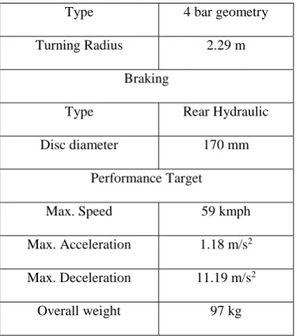
Type 4 bar geometry
Turning Radius 2.29 m
Braking
Type Rear Hydraulic
Disc diameter 170 mm
Performance Target
Max. Speed 59 kmph
Max. Acceleration 1.18 m/s2
Max. Deceleration 11.19 m/s2
Overall weight 97 kg
II. ROLLCAGEDESIGN
The primary function of roll cage is to protect the driver, give a rigid support for the assembly of sub systems, engine and drive train. The roll cage is designed to meet the technical requirements of competition. The objective of the chassis is to encapsulate all components of the kart, including a driver, efficiently and safely. Proper numbers of members are used in the roll cage to ensure complete driver safety. These include the rear roll hoop, the front and rear bumpers, the side bumper, fire extinguisher, battery cover and firewall as per the specifications in the rule book. The bumpers are so designed that they will serve as protection from front and rear and will also add impressive look to the kart. All the bends are of constant radius. In this design, use variable thickness pipes in order to reduce the weight of chassis. For primary and secondary members, 2 mm and 1.65 mm thick pipes are used respectively.
Table 2- Design parameters
Wheelbase 42”
Front Track Width 40”
Rear Track Width 42”
Height of RRH 45”
Outer Diameter 25.4 mm
Thickness 2 mm & 1.65 mm
No. of welds 34
Pipe Length 19 m
Figure 1- Chassis CAD model
Figure 2- Chassis PVC prototype A. Material
The selection of material for chassis is done by detailed study of properties of material regarding strength and cost, results found that two materials AISI 1018 and AISI 1020 which are having similar properties. But prefer to use AISI 1018 over AISI 1020, because of its higher yield strength and high strength to weight ratio.
The material AISI-1018 is used in the chassis design because of its good weld ability, relatively soft and strengthens as well as good manufacturability. A good strength material is important in a roll cage because the roll cage needs to absorb as much energy as possible to prevent the roll cage material from fracturing at the time of high impact. AISI- 1018 has chosen for the chassis because it has structural properties that provide a high strength to weight ratio.
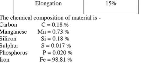
Table 3- Properties of material
Ultimate Strength 420 MPa
Yield Strength 310 MPa
Density 7870 kg/m3
Elongation 15%
The chemical composition of material is - Carbon C = 0.18 %
Manganese Mn = 0.73 % Silicon Si = 0.18 % Sulphur S = 0.017 % Phosphorus P = 0.020 % Iron Fe = 98.81 %
B. Welding
The material which is used AISI-1018 has good weld ability. All welds on the vehicle are made using a MIG (metal inert gas) welding process. MIG welding uses an arc of electricity to create a short circuit between a continuously fed anode (+ the wire fed gun) and a cathode (- the metal being weld). MIG is selected because it provided the best control of heat affected zones while also reducing internal stress in the frame selected in order to allow the weld to flex slightly without cracking. It provides strongest welds, faster welding speed and is clean and efficient makes welding easier.
C. Finite Element Analysis
Structural integrity of the frame is verified by comparing the analysis result with the standard values of the material. Analysis was conducted by use of finite element analysis FEA on ANSYS software. To conduct finite element analysis of the chassis an existing design of chassis was uploaded from the computer stresses were calculated by simulating three different induced load cases .The load cases simulated were frontal impact, side impact, and rear impact. The test results showed that the deflection was within the permitted limit.
Meshing
Auto meshing has been done in ANSYS 14.5 software. Following data has been found after meshing of chassis –
No. of Nodes = 353049 No. of Elements = 176790
Figure 3- Auto meshing in ANSYS 14.5 Front Impact
For the front impact, engine and driver load was given at respective points. The kingpin mounting points and rear wheels position kept fixed. Front impact was calculated for an
optimum speed of 60 kmph. From impulse momentum equation, 5g force has been calculated. The loads were applied only at front end of the chassis because application of forces at one end, while constraining the other, results in a more conservative approach of analysis. Time of impact considered is 0.2 seconds as per industrial standards.
F x t = m x (Vi - Vf) F x 0.2 = 180 x (16.38 - 0) F=14.7 KN
Figure 4- Deformation
Figure 5- Equivalent stresses Table 4- Frontal Impact
Deformation 1.47 mm
Max. Stress 209.4 MPa
Factor of Safety 2.04
Rear Impact
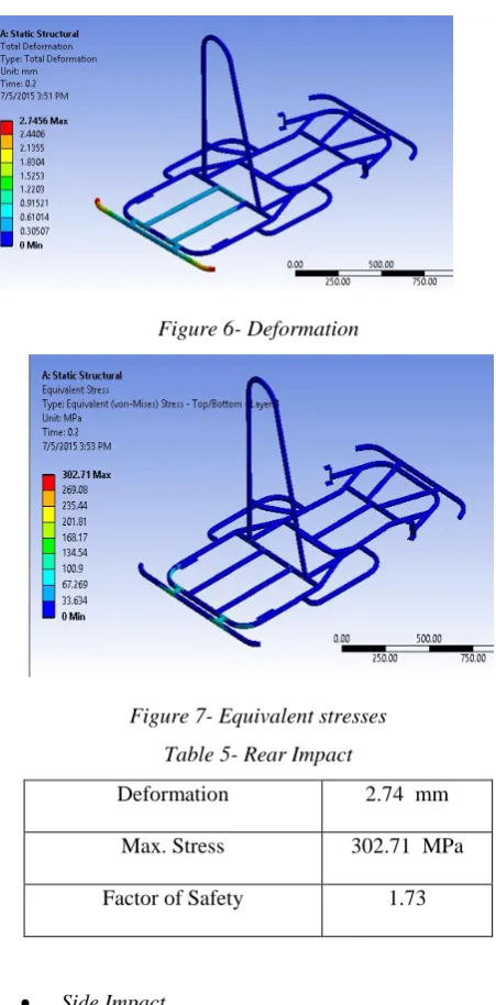
Considering the worst case collision for rear impact, force is calculated as similar to front impact for speed of 60 kmph. The value of 5g force has been calculated. Load was applied at rear end of the chassis while constraining front end and king pin mounting points. Time of impact considered is 0.2 seconds as per industrial standards.
Figure 6- Deformation
Figure 7- Equivalent stresses Table 5- Rear Impact
Deformation 2.74 mm
Max. Stress 302.71 MPa
Factor of Safety 1.73
Side Impact
The most probable condition of an impact from the side would be with the vehicle already in motion. So it was assumed that neither the vehicle would be a fixed object. For the side impact the velocity of vehicle is taken 30 kmph and time of impact considered is 0.2 seconds as per industrial standards. Impact force was applied by constraining left side of chassis and applying load equivalent to 2.5g force on the right side.
F x t = m x (Vi-Vf) F x 0.2 = 180 x (8.19 -0) F=7.35 KN
Figure 8- Deformation
Figure 9- Equivalent stresses Table 6- Side Impact
Deformation 1.46 mm
Max. Stress 277.5 MPa
Factor of Safety 1.17
Modal Analysis
Modal analysis was carried out for chassis and frequency of vibration was found to be less than desired engine frequency. The maximum frequency of chassis vibration is nearly 100 Hz and the results of analysis have been shown below. The minimum frequency of vibration for engine is above 800 Hz. So the resonance will not occur. And thus design is safe.
Figure 11- Graph of frequency
III. STEERING SYSTEM
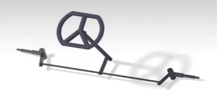
The steering system for the vehicle has to be designed to provide maximum control of the vehicle. Simplicity and safety were the main design specifications for the vehicle’s steering system. The main goal for steering is to have steering radius of 4m or less. Along with controlling the vehicle, the steering system has to provide good ergonomics and be easy to operate. After researching multiple steering systems, the four bar steering type was selected which provides easy operation, less weight, requires low maintenance, provides excellent feedback and is cost effective. Ackerman steering mechanism has been selected for steering system because it does not slip during the turning of tires and it reduces the steering efforts. The positive 3 degree caster is given for self centering of the kart. Mechanical steering linkage system has been used to make steering simple to manufacture, decrease the steering effort and the amount of steering wheel travel and increase the steering responsiveness.
Figure 12- CAD model of steering Stub Axle
The AISI 1040 steel has been selected for the design of stub axle. Force equivalent to load of front tires, cornering force of 1.2g magnitude and kingpin movement were applied to respective points while constraining the stud in all the directions. For worst condition, the deformation and stresses are as follow.
Figure 13- Deformation
Figure 14- Equivalent stresses Table 7- Analysis results
Deformation 0.14 mm
Max. Stress 62.97 MPa
Factor of Safety 3.41
Steering Calculations
The Ackerman condition is expressed as Cot θo − Cot θi = c / b
Where, θo − outer steering angle θi − inner steering angle c − distance between king pin b – wheelbase
Assuming, θi = 38o
Wheelbase (b) = 1067 mm King pin distance (c) = 769.72 mm Therefore from above condition θo = 26.54o
Now, Ackerman angle (α),
tan α = king pin distance / ( 2 x wheelbase ) therefore, α = 19.83o
Turning Radius ( R ) = ( b / sin θo ) − length of stub
axle
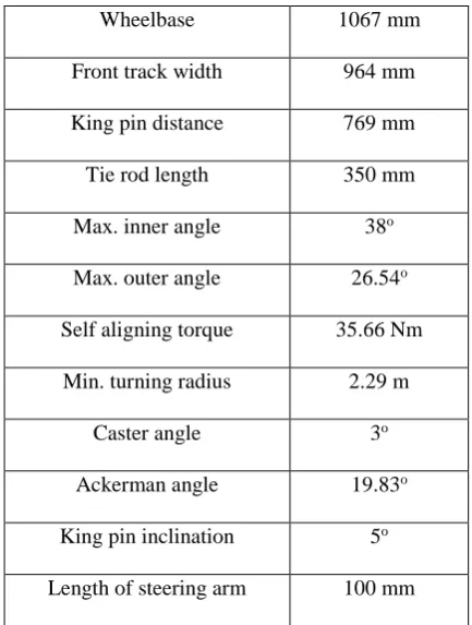
Table 8- Steering parameters
Wheelbase 1067 mm
Front track width 964 mm
King pin distance 769 mm
Tie rod length 350 mm
Max. inner angle 38o
Max. outer angle 26.54o
Self aligning torque 35.66 Nm
Min. turning radius 2.29 m
Caster angle 3o
Ackerman angle 19.83o
King pin inclination 5o
Length of steering arm 100 mm
The simulation of steering geometry has been done in ADAMS 14 and the inner & outer steering angle were calculated from it.
Figure 15- Graph of steering angle
Figure 16- Steering model in ADAMS IV. BRAKING SYSTEM
The objective of Braking System is to provide reliable and prompt deceleration of vehicle. In order to achieve maximum performance from the braking system, the brakes have been designed to lock up rear wheels, while minimizing the cost and weight. Moreover, the driver must have complete control of the vehicle while brakes are actuated. According to rule book of NKRC 2015 the vehicle travelling at 40 kmph should stop when you apply the brake. A hydraulic disc brake has been chosen as a suitable way to accomplish these requirements. The disc of diameter 170 mm, which is operated by 2 piston calliper hydraulic braking system, has been selected according to vehicle design demands. The disc is mounted on the rear axle as shown in figure below. Master cylinder is placed front side of the vehicle beside the steering column for easy maintenance.
Figure 17- Braking system Table 9- Braking parameters
Brake Type Hydraulic disc brake
Rotor Diameter 170 mm
TMC Diameter 19 mm
Caliper Piston
Diameter 24 mm
Rotor Thickness 4 mm
Pedal Force Applied 100 N
Pedal Ratio 6 : 1
Velocity 11.11
Table 10- Calculated values
Force generated by caliper 957.3 N
Pressure inside TMC 2.11 MPa
Braking force
3829.12 N Frictional force 2297.47 N
Braking torque 281.44 Nm
Deceleration 11.19 m/s2
Stopping distance
2.75 m
Tyres
Table 11- Tyres specification
Tyre Used Slick Tyres
Front Tyre Size 4.5/5-10
Rear Tyre Size 7.1/5-11
Rim Diameter 5”
V ENGINE POWER TRAIN
A single cylinder four stroke 125 cc engines is selected. So there had number of options for the selection of engine such as Honda shine, Bajaj discover, TVS Phoenix etc. After long research work and survey, it is decided to use Bajaj Discover 125 ST engine to power a kart. It have inbuilt gear box of manual 5 speed constant mesh gear box, with the multi plate wet clutch. So the design is according to the engine specification.
Table 12- Engine specification
Engine Bajaj Discover 125 ST
Max. Torque 10.8 Nm
Max. Power 13 PS
Fuel Economy 68 kmpl
Dry Weight 22 kg
Overall Dimensions 16.5” x 12.5” x 10.5”
Gearbox 5 Speed
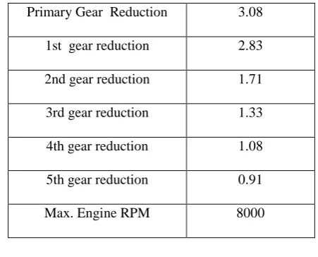
Table 13- Gear reduction values
Primary Gear Reduction 3.08
1st gear reduction 2.83
2nd gear reduction 1.71
3rd gear reduction 1.33
4th gear reduction 1.08
5th gear reduction 0.91
Max. Engine RPM 8000
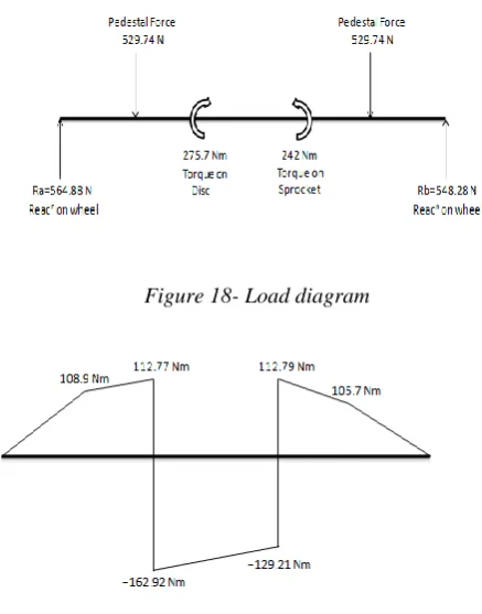
Shaft Design
The rear axle is used to transmit the power from engine to the rear tire through chain drive. It is the solid shaft of diameter 30 mm and length of 42” according to design calculations. The material used is EN8 which is also known as AISI 1040. It is the medium carbon steel with improve strength over mild steel and it is easy to machine at supplied condition. The specification and the properties of the material is given below.
Table 14- EN8 properties Mechanical Properties
Ultimate tensile strength 620 MPa
Yield strength 415 MPa
Hardness 58 Rockwell
Density 7.845 g/cc
Youngs modulus 210 GPa
Chemical Composition
Iron (Fe) 98.6 %
Manganese (Mn) 0.60 %
Carbon (C) 0.40 %
Sulphur (S) 0.050 %
Phosphorus (P) 0.040 %
Figure 18- Load diagram
Figure 19- Bending moment
Using above values, the diameter of the shaft is found to be 28.01 mm. So the diameter of the shaft is taken as 30 mm.
Chain Drive
For this system, chain drive type transmission is most preferable as it is easy to install, simple in design and cost effective. The chain type used is of roller chain and pitch of chain is decided from power rating table. After interpreting the chain data, numbers of teeth on driving sprocket are decided according to application and power of engine. The secondary gear reduction is calculated on the basis of how much maximum rpm driven sprocket should possess in order to run the kart at top speed of 60 kmph considering the transmission efficiency and manufacturing deficiencies and how much maximum rpm is available at the driving sprocket. From the analytical calculations, 1.71 is the tabulated value of secondary reduction ratio.
Table 15- Specification of chain drive
Chain
Max. torque at rear axle 242 Nm
Shock factor 1.25
Chain no 8 B
Chain pitch 12.7 mm
Length of chain 685.5 mm
No of Links 54 links
Roller diameter 8.51 mm
Gear Ratio 2.57
Diameter of shaft 30 mm
Driving Sprocket
No of Teeth 14
Pitch circle diameter 57.07 mm
Driven Sprocket
No of Teeth 36
Pitch circle diameter 145.72 mm
Figure 20- Chain drive Exhaust System
The design of exhaust needed to be in such a way that it should be lighter in weight and should have minimum resistance to gas flow (back pressure) and keeping it within the limits specified for the particular engine model and rating to provide maximum efficiency, reducing exhaust noise emission, to meet local regulations and application requirements. Providing adequate clearance between exhaust system components and engine components, machine structures, engine bays, enclosures to reduce the impact of high exhaust temperatures on such systems.
VI SUPER STRUCTURE
Aesthetics
The use of continuous bended pipes also reduced the no of joints, the lack of sharp edges on the chassis frame allows for the design of more streamlined body panels which not only look smoother, but may also have a positive effect on the overall aerodynamic drag forces.
Body Panels
The panels are designed such that they tends to reduce the aerodynamic moments like pitching from front, yawing from side and also helps to create the downward force to which tends to make the good traction of vehicle with the road & also provide the properties necessary to protect the driver and vehicle components from rocks and other debris. When the panels were integrated into the car, the panels were recessed into the chassis to provide visibility to the chassis members. The green coloured body panels made up of fibre material is used, in order to reduce the weight of kart making the car aesthetically pleasing.
Electricals
In this Go kart, 12V - 5 Ah battery is used. The parallel circuits from battery are connected to the electrical appliances such as, Starter, Ignition system, Tail lights and two kill switches. These switches are located near front side of seat and other at the right side of the driver on the rear roll hoop. In case of accident, one can use the kill switch which is placed on the right of the driver to kill the engine. Brake light is mounted on the rear end of the chassis, which is clearly seen by rear vehicles.
VII ERGONOMICS AND SAFETY
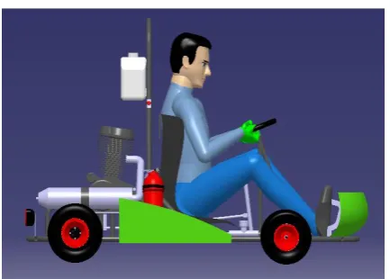
The seat in this kart is designed to be very light and is made of plastic material. It is attached to the chassis by four points along with rubber bushes to reduce vibration to increase driver’s comfort. The pedal position is ergonomically compatible with the driver’s driving style. This kart has compact cockpit which is comfortable yet safe. The steering wheel is designed so as to occupy less space and easy to steer. The kill-switch which is mounted near the front side of seat is in ease of access to the driver in case of emergency. Rear roll hoop is incorporated in order to protect the driver in case of rollover of kart. The gear shifter is placed on left hand side of driver and is easy to operate. The fire extinguisher is on right side of driver and clamped to firewall. Ease of egress is less than 3 seconds.
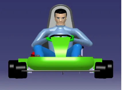
The following figure shows the driver’s sitting posture -
Figure 22- Driver ergonomics
Figure 23- Isometric view
Figure 25- Top View
Figure 26- Side View
Conclusion
Result concluded that the AISI 1018 material is more economic and gives better performance. It is also suitable for large scale production. Static analysis using finite element method was successfully carried out on chassis CAD model to determine equivalent stresses, maximum deformations, Factor of Safety and its location on chassis model. The Factor of safety calculated is found to be greater than 1. Hence the chassis design is safe.
The Engine selected and Power train designed can easily propel the Go-kart at higher speed, carrying the load of single person driving it. The Brake system is also designed so as to lock the rear wheels and stop the kart safely even at higher speeds. Also the Steering system designed for the kart gives the turning radius which satisfies the minimum condition of turning the go-kart on racing tracks.
This paper gives adequate idea and design guidelines about modeling of Go-Kart. Thus after all the analysis and design calculation, It concluded that our design of Go-kart is safe for fabrication using healthy manufacturing practices.
References
[1] AritraNath, C.JagadeeshVikram, “Design and Fabrication of a GoKart”International Journal of Innovative Research in Science, Engineering and Technology, Vol. 4, Issue 9, September 2015, ISSN No.: 2319-8753.
[2] Dr. D. Ravikanth , C. Nagaraja, “Fabrication of a Model Go-Kart (With Low Cost)” Journal of Mechanical and Civil Engineering (IOSR-JMCE) e-ISSN: 2278-1684,p-ISSN: 2320-334X, Volume 12, Issue 6 Ver. V (Nov. - Dec. 2015), PP 24-30 www.iosrjournals.org.
[3] A. A. Faieza, “Design and fabrication of a student competition based racing car” Scientific Research and Essay Vol. 4 (5) pp. 361-366, May, 2009 ISSN(online):1992-2248 © 2009 Academic Journals, www.academicjournals.org/SRE
[4] Aniket Mind, “Preliminary Design Report, NGKC 2014”,Team Nexus Racing, Sinhgad Academy of Engineering , Pune
[5] N. R. Patil, Ravichandra R. Kulkarni, “Static analysis of Go-Kart Chassis frame by Analytical and SolidWorksSimulation”, International Journal of Scientific Engineering and Technology, Volume No.3 Issue No.5, 1 May 2014, pp : 661-663, (ISSN : 2277-1581).
[6] Mr. GirishMekalke, “Static Analysis of a Go-kart Chassis” , International Journal of Mechanical and Industrial Technology,Vol. 3, Issue 2, pp: (73-78), Month: October 2015 - March 2016,ISSN 2348-7593 (Online), www.researchpublish.com
[7] Muhammad Bin Zulkifly, “Design and Fabricate Braking system For the Electric Buggy Car”, University Malaysia Pahang, November 2007.
[8] Xiang Liu,” Design of an Ackermann-type steering Mechanism”, article in Archive Proceedings of the Institution of Mechanical Engineers part C journal of Mechanical Engineering Science 1989-1996 (vol.203-210) November 2013.
[9] Rahul Thavai, Quazi Shahezad, Mirza Shahrukh, “Static Analysis of GoKart Chassis by Analytical and Solid Works Simulation”, International Open Access Journal of Modern Engineering Research (IJMER) Vol. 5, Iss.4, Apr. 2015.
[10] R. S. Khurmi, “A Textbook of Machine Design”, Eurasia
Publications house pvt. Ltd. fourteenth edition, 2005
[11] Thomas D. Gillespie, “Fundamentals of Vehicle Dynamics” Society of Automotive Engineers Inc. Publications.
[12] John B. Heywood, “Internal Combustion Engine Fundamentals”, Mc Graw Hill Inc. Publications.
[13] William F. Milliken and Douglas F. Milliken, “Race Car
Vehicle Dynamics”, Milliken Research Associates Inc. Publications