Volume 56, 2018, Pages 52–62
Proceedings of the 5th International OMNeT++ Community Summit
Migration from SERCOS III to TSN - Simulation Based
Comparison of TDMA and CBS Transportation
Sebastian Szancer, Philipp Meyer, and Franz Korf
Department of Computer Science
Hamburg University of Applied Sciences, Germany
{Sebastian.Szancer, Philipp.Meyer, Franz.Korf}@haw-hamburg.de
Abstract
The communication infrastructure of industrial plants, vehicles and many other appli-cations must provide more and more bandwidth, sometimes with strict timing requirements for the transmission of critical data. Time-Sensitive Networking (TSN) is a set of IEEE 802 Ethernet sub-standards that meet these requirements for a wide range of applications and communication requirements. Market relevance of TSN increases in different sectors. On the other hand, SERCOS III is an established Ethernet-based communication standard, which is used in particular in the field of industrial plants. With cost and limitations of SERCOS III in mind, this paper examines the migration from SERCOS III Time Division Multiple Access (TDMA) communication on the one side to Credit Based Shaping (CBS) communication on the other side. TSN supports both mechanisms. The analyses are per-formed with OMNeT++ simulation models. Migration recommendations are derived from the comparison of TDMA- and CBS-based transportation of SERCOS III traffic.
1
Introduction
In industrial plants, Ethernet-based communication structures that guarantee Quality of Service (QoS) statements such as jitter or End-to-End (E2E) latency are already in use for some time. Some of them run on standard Ethernet hardware, others need adjustments on the data link layer. Usually these protocols support the synchronization of all network node clocks.
SERCOS III is such a protocol [10,11]. A SERCOS III network is a closed communication network in which the participants are linked in a ring or line topology. These participants communicate using a Time Division Multiple Access (TDMA) approach. For each link of the network, a periodic schedule allocates timeslots for frames that contain real-time relevant data. Best Effort (BE) traffic, which does not have to comply with time requirements, will be transferred in the remaining time slots of this schedule.
In addition to this cost advantage, flexible topologies supported by TSN are a major reason for migration from SERCOS III to TSN. SERCOS III requires a ring or line topology that contains only SERCOS III capable components. This daisy chain topology results in relatively high transmission times between nodes higher hop count distances. TSN, on the other hand, supports arbitrary topologies in which non-TSN capable nodes, which only use BE traffic, are integrated. In particular, the daisy chain topology of SERCOS III can be divided into parallel logical sub-lines for accelerating End-2-End (E2E) latency [13].
Migration from SERCOS-III to TSN involves three subtasks:
(1) Clock synchronization: SERCOS III synchronizes the clocks of all nodes. This shared time base is required for sending the frames according to the TDMA schedule. Furthermore, applications also use the synchronous clocks. SERCOS III binds the clock synchronization to the first TDMA frame of a schedule period. The migration to TSN removes this coupling. Instead, the IEEE 802.1AS protocol defined in TSN is used [2].
(2) Adaption of application interface: SERCOS III spans this interface over several frames, which are sent by a master and forwarded between the participants. The protocol participants read data out of these frames and write data into these frames, too. Often this interface is deeply integrated into applications. Hence migration must and does not change this interface. (3) Transportation of time critical data according to given QoS requirements: On data link layer TSN defines mechanisms for the implementation of QoS requirements. They are based on procedures for choosing the next frame to be sent via a physical link. As defined in IEEE 802.1Qbv [8] TSN supports a TDMA-based approach through a offline configuration of a timed transmission gate behavior. Unlike SERCOS III, TSN schedules could be defined for any Ethernet topology of switches and end nodes, not just line topology. Additionally, the Credit Based Shaper (CBS) defined in IEEE 802.1Qav [4] can be used in TSN as a transmission selection algorithm for asynchronous traffic. Here, the required communication behavior will be modelled using several classes of streams that are dynamically allocable. For each physical link a credit gradient defines the bandwidth reserved for a stream class. A CBS selects the next frame that should be transmitted over a link.
Since SERCOS III is based on a TDMA approach the mapping from SERCOS III to TSN TDMA traffic is straight forward and will lead to similar QoS statements. If SERCOS III will be mapped to CBS traffic, additional parameters, such as reserved bandwidth or the maximum frame size of BE traffic, affect QoS statements. On the other hand, CBS allows higher flexibility. This paper gives criteria for choosing a suitable method for the transportation of SERCOS III traffic via TSN.
2
Background & Related Work
The first two paragraphs of this section give the basics of Time-Sensitive Networking and SERCOS III. Finally, related work is presented and differentiated.
2.1
Time-Sensitive Networking
TSN is a set of a real-time Ethernet protocol. It is composed of a set of IEEE standards, which are adapted to real-time control stream network requirements. Typical domains of application for TSN include industrial control facilities, airplanes or cars.
IEEE 802.1AS Timing and Synchronization for
Time-Sensitive Applications in Bridged Local Area
Networks
IEEE 802.1Qcc Stream Reservation
Protocol (SRP) Enhancements and
Performance Improvements
IEEE 1722 (+ IEEE 1722.1)
Layer 2 Transport Protocol for Time Sensitive Applications in a Bridged Local Area Network
IEEE 802.1Qbv Enhancements for
Scheduled Traffic
IEEE 802.1Qbu Frame preemption
IEEE 802 Ethernet
IEEE 802.1Qci Per-Stream Filtering
and Policing
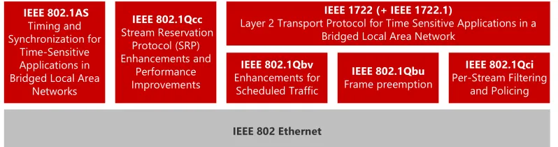
Figure 1: Time-Sensitive Networking standards
Figure 1 shows relevant parts of this collection. The first one is the IEEE 802.1AS [2] defining the time synchronization of TSN network nodes. In TSN synchronized time enables the modelling of TDMA traffic and synchronised application behavior. Secondly IEEE 802.1Qcc [3] describes the dynamic route and bandwidth reservation over the network. IEEE 802.1Qbv [8] provides a set of forwarding and queueing strategies to handle the transmission order of frames on a link. Using these strategies in parallel, TSN supports different synchronous -and asynchronous transportation mechanisms, like TDMA -and CBS, on the same physical link at link layer. The next standard is IEEE 802.1Qbu [7]. It contains the function of frame preemption. This allows to interrupt a packet in transmission for a higher priority frame. IEEE 802.1Qci [9] describes an ingress control through per-stream filtering and policing. The Last one in this set of standards is the IEEE 1722 transport protocol specified in IEEE 1722 [5] and IEEE 1722.1 [6].
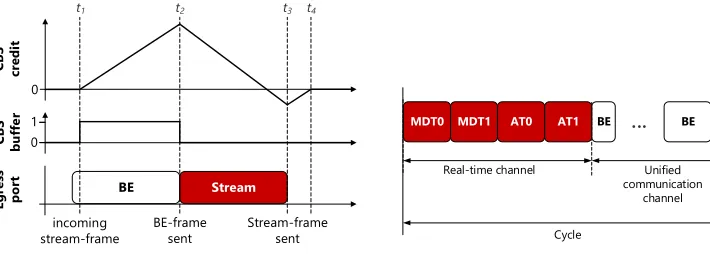
Audio Video Bridging (AVB) is the predecessor of TSN. The AVB standard IEEE 802.1Qav [4] defines an asynchronous forwarding strategy implemented by a Credit Based Shaper (CBS). As given in IEEE 802.1Qbv [8] the CBS can be used in TSN as a transmission selection algo-rithm. The CBS defines two QoS classes. Class A enables a maximum latency of 2 ms over 7 hops. For class B a maximum latency of 50 ms is guaranteed. The CBS shapes streams of frames according to a pre-reserved bandwidth by ensuring that the bandwidth is met in a class measurement interval (Class A: 125µs, Class B: 250µs). The CBS algorithm is based on a credit value, manipulated by two different gradients called ”idleslope” and ”sendslope”. They are composed of the reserved bandwidth (Breserved) and the total bandwidth (Btotal) of the corresponding egress port.
idleslope=Breserved (1) sendslope=Breserved−Btotal (2)
greater or equal to 0, an stream-frame will be transmitted. Otherwise it waits in the CBS buffer of the port. While the credit is negative or the CBS buffer is not empty, the credit increases according to the ”idleslope” (see interval [t1, t2] and [t3, t4]). During the transmission of an
stream-frame, the credit decreases according to the ”sendslope” (see interval [t2, t3]). If the
CBS buffer is empty the credit stays at 0 (seet4) or will be decreased to 0.
0
0
BE Stream
Egr
es
s
po
rt
CB
S
bu
ff
er
CB
S
cr
ed
it
incoming
stream-frame BE-framesent Stream-framesent
1
t1 t2 t3 t4
Figure 2: Credit Based Shaping example
BE MDT0
Real-time channel Unified communication
channel
Cycle
AT0 BE MDT0
MDT1 AT1
...
Figure 3: SERCOS III example
2.2
Sercos III
SERCOS III (Serial Real-time Communication System) is a TDMA-based real-time Ethernet protocol that supports standard and real-time Ethernet communication simultaneously. It is defined in the IEC standards IEC 61158-1:2014[10] and IEC 61784-2:2014[11]. The entire bandwidth is divided into two channels: a real-time channel (RTC) and a channel for standard Ethernet communication (Unified Communication Channel: UCC) (see figure3). Data is sent in cycles consisting of RTC and UCC phases. Each cycle starts with the RTC phase in which a fixed number of real-time frames, called telegrams, are sent. Afterwards standard Ethernet frames can be sent during the UCC phase. The transmission of the last BE frame must be finished at the end of the UC channel.
SERCOS III is a master-slave protocol with exactly one master. It supports either a physical line or ring topology. The ring topology is used for redundancy reasons. A SERCOS III network does not contain a switch. Instead, each node has two ports. The nodes are arranged in a chain. Thus, the network contains only SERCOS III nodes.
topology, the master sends two copies of each telegram. One telegram is send to the right slave in the ring and the other to the left slave in the ring. Both copies traverse the entire ring till received by the master.
2.3
Related Work
Based on an OMNeT ++ simulation, Nsaibi et al. investigate a network that consists of a TSN switch and several regular SERCOS III chains [13]. Using a TSN switch with 1 Gbit links, they change the standard line topology to a tree topology. This approach reduces the SERCOS III cycle time. By using the TDMA capabilities of TSN the accurate timing of MDTs is still present even with cross-traffic on the switch. Hence, slaves can still be synced with the MDT0. Just the master and the switch are using an additional synchronisation protocol.
In our approach all devices have an additional TSN stack so that the correct timing of MDT0 frames is not necessary. All participants can instead be synchronised with the TSN synchro-nisation protocol. This enables the transport of MDTs through asynchronous traffic. Hence, our approach still supports the line topology of SERCOS III, but any TSN network topology between the slaves is supported, too. Additionally we also add cross-traffic between slaves.
Guti´errez et al.[1] study the synchronisation quality of the TSN protocol IEEE 802.1AS [2] in large-scale industrial automation networks. Their definition of large-scale are chains with a length of 100 hops. To analyse the performance of IEEE 802.1AS they use a simulation model based on OMNeT++ and the INET framework. The results show that the synchronisation precision is 2µs for the last node in a 100 hop chain. A precision of 1µs is achievable with a chain length of maximum 30 hops.
We assume a TSN synchronised system in our approach. Additionally in case of asynchronous transmission the synchronisation precision is only dependent on the application requirements.
TSN and its predecessor AVB support compliance with QoS requirements for Ethernet-based communication. Using OMNeT++ simulation models, various papers explore the benefits of TSN- and AVB-based communication in different real-time applications, e.g. [12,15].
Steinbach et al.[16] analyse the robustness of real-time traffic for in-car Ethernet networks against cross-traffic. This analysis is based on OMNeT++ simulations, too. They show that cross-traffic can have significant influence on the real-time traffic performance. The authors propose strategies like limiting MTU, limiting cross-traffic, increase bandwidth and preemption to increase the performance of concurrent real-time traffic. In our work we consider these results to analyse the impact of cross-traffic in a SERCOS-III - TSN hybrid scenario.
3
The Simulation Model
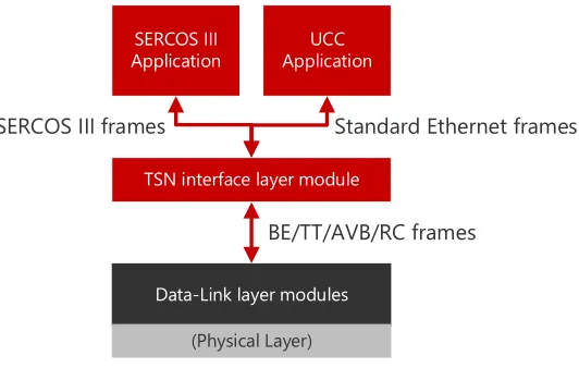
On top of CoRE4INET we implemented a SERCOS III framework. It consists of three layers: Application layer, data link layer and TSN interface layer. The last one provides an interface for the application layer to access the data link layer. The model provides a SERCOS III device compound module, SERCOS III application modules (a master and a slave application module) and TSN interface modules. It also provides applications for generating configurable best-effort cross-traffic. The TSN interface modules allow the mapping of SERCOS III on different Ethernet transportation mechanisms (TDMA, CBS), which are implemented in the CoRE4INET framework. SERCOS III applications and cross-traffic generators run on the application layer.
Data-Link layer modules
(Physical Layer)
TSN interface layer module
BE/TT/AVB/RC frames
SERCOS III
Application ApplicationUCC
Standard Ethernet frames SERCOS III frames
Figure 4: SERCOS III node components
So each SERCOS III device consists of an application module, a TSN interface layer module, data link - and physical layer modules. Best-effort traffic generators, are optional. The modules communicate via messages, which is the standard mechanism for inter-module communication in OMNeT++.
4
Case Study
Based on the simulation model given in the previous section the following case study analyses a network that shows the flexibility gained by the migration of SERCOS III to TSN. CBS-and TDMA-based transportation of SERCOS III traffic will be compared. Finally, some design recommendation regarding the use of different TSN traffic classes will be given.
4.1
Scenario
Figure5 gives a network topology consisting of SERCOS III nodes and switches that support TDMA, CBS and best effort traffic. Please be aware that any nodes, which generate arbitrary traffic, may be added to the network. The network consists of one master, 9 SERCOS-slaves and 3 switches. Instead of using a simple physical line or ring, a more complex topology was chosen. The SERCOS-slaves are divided into 3 parallel lines, with 3 slaves in each line. The third one is a logical line composed of slaves and switches. A 1 Gbit/s link connects the SERCOS-master to the first switch. All remaining links of the network are 100 Mbit/s links.
Cross-traffic: f=130 - 260µs
Cross-traffic: f=130 - 260µs
Cross-traffic: f=260 - 390µs
Cross-traffic: f=260 - 390µs
chain1slave1 chain1slave2 chain1slave3
switch1
chain2slave1 chain2slave2 chain2slave3
master
switch2 chain3slave1
switch2 chain3slave2 chain3slave3
Figure 5: Switched SERCOS III network topology
SERCOS III via TDMA The first setup transports SERCOS III via Time-Triggered Ether-net TDMA traffic. The size of the SERCOS III payload was set to 30 B resulting in a SERCOS III frame size of 48 B without padding. The resulting Ethernet frame has a size of 66 B due to the encapsulation of the SERCOS III frame. The processing delay of a TSN switch and a SER-COS III device, including the processing time of application logic, was set to 4.6µs [17]. Due to the synchronization of all clocks of all nodes, there is no need for the clock-synchronization mechanism of SERCOS III. The maximum clock-jitter of all devices was set to 400 ns.
To examine how suitable TDMA is for transportation of SERCOS III traffic in real-life environments characterized by best-effort cross-traffic, the simulation was run with varying amounts of such best-effort cross-traffic generated by SERCOS-nodes. Maximum transmission unit (MTU) and transmission frequency of the cross-traffic varies by a uniform distribution. The MTU was distributed in the range between 800 B and 1500 B. To achieve a significant network load, best-effort frames were sent across selected routes. Figure 5 shows the routes and its uniform distributions of the transmission frequency (f). The TDMA schedule was configured to achieve the best possible round-trip time (RTT): every frame is sent without delay (not counting the processing delay of a device).
SERCOS III via CBS This setup transports SERCOS III via CBS on the data link layer. For the SERCOS III frames SR-class A has been chosen, for best possible performance. The CBS stream frame interval parameter is set to 4 frames per class measurement interval of 125µs. Due to the Ethernet IEEE 802.1Q header of stream-frames the size of Ethernet frames increases to 70 B. The resulting reserved bandwidth is approx. 23 Mbit/s per stream.
In order to compare TDMA-based transportation to CBS-based transportation both exper-imental setups use the same MTU and transmission frequency parameters for cross-traffic. To show the effect of limiting MTU of best-effort frames on the SERCOS III traffic, an additional simulation increases MTU by 100 B in the range from 100 B to 1500 B. To illustrate the influ-ence of frame transmission durations on the transmission of SERCOS III traffic via CBS, an additional network variant is simulated that consists purely of 1 Gbit/s links.
4.2
Comparison & Results
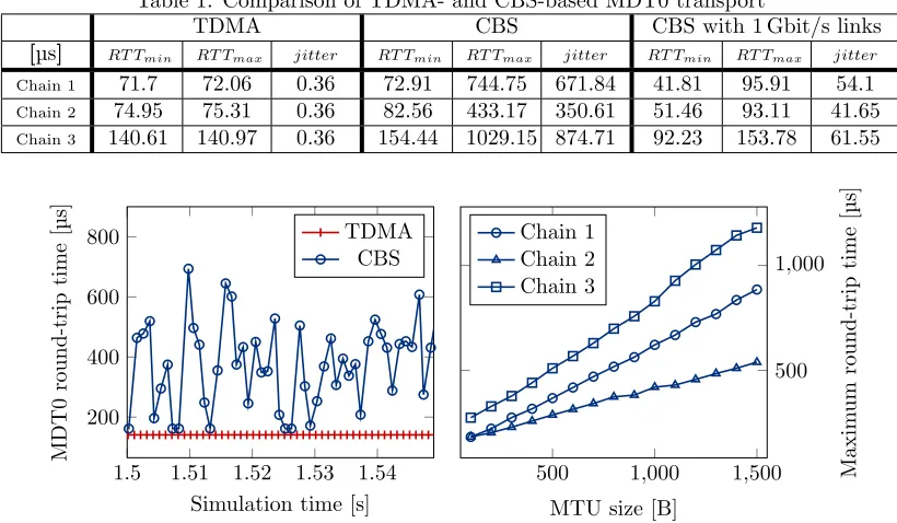
Table1 gives round-trip times (RTT) and jitters. For each of the three parallel lines (chains) minimum and maximum RTT of SERCOS III MDT0 telegrams are listed for TDMA, CBS and CBS with 1 Gbit/s links. The best RTT could be achieved using TDMA. Although the minimum RTT using CBS does not deviate more than 11% from TDMA, the maximum RTT is significantly higher. However using CBS with 1 Gbit/s links results in maximum RTT that is at most 34% higher than for TDMA traffic. Chain 1 and chain 2 have the same topology, but the corresponding RTTs for TDMA-based transportation differ. This is due to the fact that the telegrams of both chains are created at the same time and the master has to send the telegrams in sequential order over the link. Therefore the messages of chain 2 are delayed in the master node.
As expected, the jitter for TDMA-based transportation is very small (less than 1µs). In general, concerning the maximum round-trip time and jitter a better performance could be achieved using TDMA communication. Figure6 shows the direct comparison of TDMA and CBS exemplary for the telegram MDT0 of chain 3 in an arbitrary time window after the network was initialized and is in normal operation. The nearly constant RTT of the TDMA traffic (approx. 141µs) is the lower limit of the CBS traffic RTT.
Table 1: Comparison of TDMA- and CBS-based MDT0 transport
TDMA CBS CBS with 1 Gbit/s links
[µs] RT Tmin RT Tmax jitter RT Tmin RT Tmax jitter RT Tmin RT Tmax jitter
Chain 1 71.7 72.06 0.36 72.91 744.75 671.84 41.81 95.91 54.1
Chain 2 74.95 75.31 0.36 82.56 433.17 350.61 51.46 93.11 41.65
Chain 3 140.61 140.97 0.36 154.44 1029.15 874.71 92.23 153.78 61.55
1.5 1.51 1.52 1.53 1.54 200
400 600 800
Simulation time [s]
MDT0
round-trip
time
[
µ
s]
TDMA CBS
Figure 6: Latency vector of TDMA- and CBS-based MDT0 transportation
500 1,000 1,500 500 1,000
MTU size [B]
Maxim
um
rou
nd-trip
time
[
µ
s]
Chain 1 Chain 2 Chain 3
Figure 7: Maximum CBS transport RTT in dependency of cross-traffic MTU
Limiting the best-effort frame MTU proved to be another way to reduce the RTT of the CBS communication. Figure 7 shows this effect in network with 100 Mbit/s links. The maximum delay imposed by cross-traffic in the CBS shaping is just dependent on the cross-traffic frame sizes. So the maximum CBS traffic RTT can be reduced by limiting the MTU even if the cross-traffic bandwidth stays at the same level.
Depending on the performance requirements of a given application either CBS or TDMA can be chosen for the transportation of SERCOS III traffic. If the performance with CBS is sufficient, it should be chosen due to its higher flexibility. In contrast to TDMA, CBS does not require a static off-line configuration of the entire schedule.
5
Conclusion
Based on an OMNeT++ simulation, this paper examined the migration from a SERCOS III network to a TSN network. This leads to a more flexible network designs as well as to a possible cost reduction through the use of components of a larger sales market.
The transportation of SERCOS III telegrams via TDMA and CBS frames was investigated. As expected the TDMA-based approach provides the best performance concerning maximum RTT and jitter. It is similar to the one of SERCOS III networks. On the other hand, CBS-based transportation of SERCOS III telegrams supports a more flexible network design. But this approach leads to higher maximum RTT and jitter, which are significantly above the values of SERCOS III networks. As shown for CBS-based transportation, RTT and jitter can be improved by fragmentation of best effort cross traffic or a higher link bandwidth.
For SERCOS III applications, which place high demands on temporal synchronization of applications and transmission of data themselves, the migration to the TDMA-based approach is appropriate. Unlike SERCOS III, TSN decouples clock synchronization and data transmission. Thus, for SERCOS III applications, which place moderat demands on data transmission jitter, migration to a CBS-based approach, providing greater flexibility, may be appropriate.
References
[1] M. Guti´errez, W. Steiner, R. Dobrin, and S. Punnekkat. Synchronization quality of ieee 802.1as in large-scale industrial automation networks. In2017 IEEE Real-Time and Embedded Technology and Applications Symposium (RTAS), pages 273–282, April 2017.
[2] IEEE 802.1 TSN Task Group. IEEE 802.1AS-Rev - Timing and Synchronization for Time-Sensitive Applications.
[3] IEEE 802.1 TSN Task Group. IEEE 802.1Qcc - Stream Reservation Protocol (SRP) Enhancements and Performance Improvements.
[4] Institute of Electrical and Electronics Engineers. IEEE 802.1Qav - IEEE Standard for Local and metropolitan area networks - Virtual Bridged Local Area Networks - Amendment 12: Forwarding and Queuing Enhancements for Time-Sensitive Streams. Standard IEEE 802.1Qav-2009, IEEE, December 2009.
[5] Institute of Electrical and Electronics Engineers. IEEE Standard for Layer 2 Transport Protocol for Time Sensitive Applications in a Bridged Local Area Network. Standard, IEEE, May 2011. [6] Institute of Electrical and Electronics Engineers. IEEE Standard for Device Discovery, Connection
Management, and Control Protocol for IEEE 1722(TM) Based Devices. Standard, IEEE, October 2013.
[7] Institute of Electrical and Electronics Engineers. IEEE Standard for Local and metropolitan area networks – Bridges and Bridged Networks – Amendment 26: Frame Preemption. Standard, IEEE, August 2016.
[8] Institute of Electrical and Electronics Engineers. IEEE Standard for Local and metropolitan area networks – Bridges and Bridged Networks - Amendment 25: Enhancements for Scheduled Traffic. Standard, IEEE, March 2016.
[9] Institute of Electrical and Electronics Engineers. IEEE Standard for Local and metropolitan area networks–Bridges and Bridged Networks–Amendment 28: Per-Stream Filtering and Policing. Standard, IEEE, September 2017.
[11] International Electrotechnical Commission. Industrial communication networks - Profiles - Part 2: Additional fieldbus profiles for real-time networks based on ISO/IEC 8802-3. Standard IEC 61784-2:2014, IEC, 2014.
[12] Hyung-Taek Lim, Daniel Herrscher, Martin Johannes Waltl, and Firas Chaari. Performance anal-ysis of the ieee 802.1 ethernet audio/video bridging standard. In Proceedings of the 5th Inter-national ICST Conference on Simulation Tools and Techniques, pages 27–36, New York, March 2012. ACM-DL.
[13] S. Nsaibi, L. Leurs, and H. D. Schotten. Formal and simulation-based timing analysis of industrial-ethernet sercos iii over tsn. In 2017 IEEE/ACM 21st International Symposium on Distributed Simulation and Real Time Applications (DS-RT), pages 1–8, October 2017.
[14] Society of Automotive Engineers - AS-2D Time Triggered Systems and Architecture Committee. Time-Triggered Ethernet AS6802. SAE Aerospace, November 2011.
[15] Till Steinbach, Hyung-Taek Lim, Franz Korf, Thomas C. Schmidt, Daniel Herrscher, and Adam Wolisz. Tomorrow’s In-Car Interconnect? A Competitive Evaluation of IEEE 802.1 AVB and Time-Triggered Ethernet (AS6802). In2012 IEEE Vehicular Technology Conference (VTC Fall), Piscataway, NJ, USA, September 2012. IEEE Press.
[16] Till Steinbach, Hyung-Taek Lim, Franz Korf, Thomas C. Schmidt, Daniel Herrscher, and Adam Wolisz. Beware of the Hidden! How Cross-traffic Affects Quality Assurances of Competing Real-time Ethernet Standards for In-Car Communication. In2015 IEEE Conference on Local Computer Networks (LCN), pages 1–9, October 2015. LCN Best Paper Award.