IJEDR1504170
International Journal of Engineering Development and Research (www.ijedr.org)962
Mathematical modeling and speed control of BLDC
Motor Using GA and PID
1
Prachi Sahu,
2Ashish Sahu
1ME Scholar, 2 Dept. of Electrical Engg. Assistant Professor, 1Electrical Department,
1 RCET Bhilai, Bhilai(Chhattisgarh), India
________________________________________________________________________________________________________ Abstract - This paper presents the modeling of three phase brushless DC motor along with the speed regulation scheme with trapezoidal back-emf consideration. Permanent magnet synchronous motor with a trapezoidal back EMF waveform shape is conventionally called as Brushless DC motor (BLDC). In this project, GA tuned is better than PID is shown which results in a better optimization of the process.
Index Terms - BLDC, PID controller, GA controller.
________________________________________________________________________________________________________
I.INTRODUCTION
A motor that retains the characteristics of a dc motor but eliminates the commutator and the brushes is called a Brushless DC motor. Brushless DC (BLDC) motors can in many cases replace conventional DC motors. They are driven by dc voltage but current commutation is done by solid state switches i.e., the commutation is done electronically. BLDC motors are available in many different power ratings, from very small motors as used in hard disk drives to large motors in electric vehicles. Three phase motors are most common but two phase motors are also found in many applications. The BLDC motors have many advantages over brushed DC motors. A few of these are:
Higher speed ranges Higher efficiency
Better speed versus torque characteristics Long operating life
Noiseless operation
Higher dynamic response [2].
A three phase BLDC Motor has three phase stator winding on stator and permanent magnet rotor. The torque developed in BLDCM is affected by the waveform of back- Emf waveform. Usually the BLDCM has trapezoidal back- Emf waveform and stator is fed by rectangular stator current and theoretically it gives a constant torque but the torque ripple exists due to emf waveform imperfection, current ripple and phase current commutation[3].
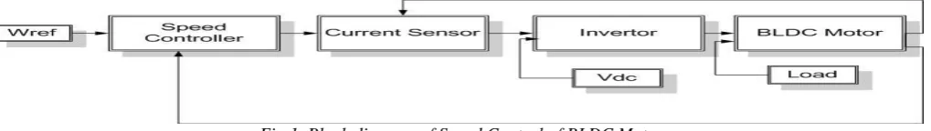
Brushless DC motor is one of a small-scale motor used in small electric devices like CD players, hard disk drives, or even small electric cars. Its rotor is mounted with permanent magnet. There is no need for extra field excitation. BLDC is well-known and popular for position and speed control drive applications [1].This presents a BLDCM Model with the trapezoidal and sinusoidal back-EMF waveform. The block diagram of BLDC Motor control system is shown in fig.1
Fig 1. Block diagram of Speed Control of BLDC Motor
II.PRINCIPLES OF THE BLDC MOTOR
2.1Mathematical Model of BLDC Motors
Modeling of a BLDC motor can be developed in the similar manner as a three-phase synchronous machine [1, 2]. Since rotor of this motor is mounted with a permanent magnet, some dynamic characteristics are different. Flux linkage from the rotor is dependent upon the magnet. Therefore, saturation of magnetic flux linkage is typical for this kind of motors. As any typical three-phase motors, one structure of the BLDC motor is fed by a three-three-phase voltage source as shown in Fig. 1. The source is not necessary to be sinusoidal. Square wave or other wave shape can be applied as long as the peak voltage is not exceeded the maximum voltage limit of the motor. Similarly, the model of the armature winding for this motor is expressed as follows:
𝑉𝑎= 𝑅𝑖𝑎+ 𝐿 𝑑𝑖𝑎
IJEDR1504170
International Journal of Engineering Development and Research (www.ijedr.org)963
𝑉𝑏 = 𝑅𝑖𝑏+ 𝐿𝑑𝑖𝑏
𝑑𝑡 + 𝑒𝑏 (2)
𝑉𝑐= 𝑅𝑖𝑐+ 𝐿 𝑑𝑖𝑐
𝑑𝑡 + 𝑒𝑐 (3)
in the compact matrix form as follows: [
𝑉𝑎
𝑉𝑏
𝑉𝑐
] = [
𝑅 + 𝑝𝐿 0 0
0 𝑅 + 𝑝𝐿 0
0 0 𝑅 + 𝑝𝐿
] [ 𝑖𝑎 𝑖𝑏 𝑖𝑐 ] + [ 𝑒𝑎 𝑒𝑏 𝑒𝑐
] (4)
where, 𝐿𝑎= 𝐿𝑏 = 𝐿𝑐= 𝐿 = 𝐿𝑠− 𝑀[𝐻]
𝐿𝑠 is armature self-inductance
M is Mutual inductance
𝑅𝑎= 𝑅𝑏= 𝑅𝑐= 𝑅 are the armature resistance in ohm
𝑉𝑎, 𝑉𝑏, 𝑉𝑐 are the terminal phase voltages in volts
𝑖𝑎, 𝑖𝑏, 𝑖𝑐 are the motor input currents in amp.
𝑒𝑎,𝑒𝑏, 𝑒𝑐 are the motor back emf in volts
p is the matrix represents d⁄dt
Fig. 2 BLDC Motor Control System
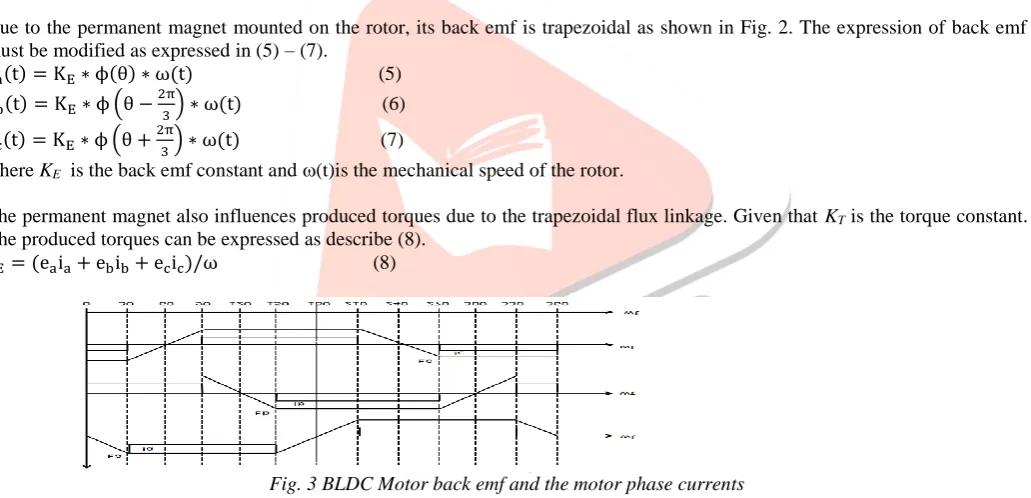
Due to the permanent magnet mounted on the rotor, its back emf is trapezoidal as shown in Fig. 2. The expression of back emf must be modified as expressed in (5) – (7).
ea(t) = KE∗ ϕ(θ) ∗ ω(t) (5)
eb(t) = KE∗ ϕ (θ − 2π
3) ∗ ω(t) (6)
ec(t) = KE∗ ϕ (θ + 2π
3) ∗ ω(t) (7)
where KE is the back emf constant and (t)is the mechanical speed of the rotor.
The permanent magnet also influences produced torques due to the trapezoidal flux linkage. Given that KTis the torque constant.
The produced torques can be expressed as describe (8). TE= (eaia+ ebib+ ecic)/ω (8)
Fig. 3 BLDC Motor back emf and the motor phase currents
Substitute (5) – (7) into (8), the resultant torque, TE, can be obtained by the following expressions.
Ta(t) = KT∗ ϕ(θ) ∗ ia(t) (9)
Tb(t) = KT∗ ϕ (θ − 2π
3) ∗ ib(t) (10)
Tc(t) = KT∗ ϕ (θ + 2π
3) ∗ ic(t) (11)
TE(t) = 𝑇𝑎(𝑡) + 𝑇𝑏(𝑡) + 𝑇𝑐(𝑡) (12)
With the Newton’s second law of motion [5], the angular motion of the rotor can be written as follows. TE(t) − TL(t) = 𝐽
𝑑𝜔(𝑡)
𝑑𝑡 + 𝐵 ∗ 𝜔(𝑡) (13)
where, TL is load torque in N-m
J is rotor inertia in kg-m2
B is damping constant
III.PIDCONTROLLER
PID controller consists of Proportional Action, Integral Action and Derivative Action. It is commonly refer to Ziegler-Nichols PID tuning parameters. It is by far the most common control algorithm [1].
In proportional control,
IJEDR1504170
International Journal of Engineering Development and Research (www.ijedr.org)964
It uses proportion of the system error to control the system. In this action an offset is introduced in the system.In Integral control,
Iterm= Ki X ∫Error dt (15)
It is proportional to the amount of error in the system. In this action, the I-action will introduce a lag in the system. This will eliminate the offset that was introduced earlier on by the P-action.
In Derivative control, 𝐷𝑡𝑒𝑟𝑚= 𝐾𝐷
𝑑𝐸𝑟𝑟𝑜𝑟
𝑑𝑡 (16)
It is proportional to the rate of change of the error. In this action, the D-action will introduce a lead in the system. This will eliminate the lag in the system that was introduced by the I-action earlier on.
𝑀(𝑆)
𝐸(𝑆) = 𝐾𝑃+ 𝐾𝐼
𝑆 + 𝐾𝐷𝑆 (17)
Where: E(s) is error input signal, M(s) is manipulated output signal. KP is proportional gain,
KI is integral gain and KD is derivative gain.
These parameters KP, KI and KD are chosen to meet prescribed performance criteria, classically specified in terms of rise and settling times, overshoot, and steady-state error. Block diagram of optimal PID control for the BLDC motor is shown in Fig.4.
Fig.4 Block diagram of PID control of BLDC motor.
IV.GENETICALGORITHEM
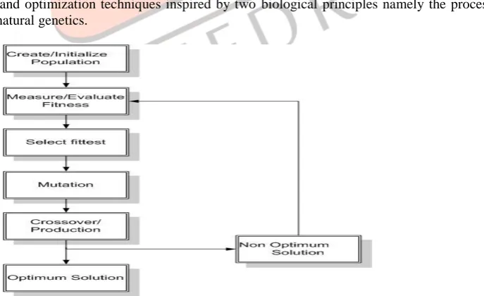
Genetic Algorithms (GA.s) are a stochastic global search method that mimics the process of natural evolution. It is one of the methods used for optimization. The genetic algorithm starts with no knowledge of the correct solution and depends entirely on responses from its environment and evolution operators such as reproduction, crossover and mutation to arrive at the best solution. By starting at several independent points and searching in parallel, the algorithm avoids local minima and converging to sub optimal solutions.
Genetic Algorithms are search and optimization techniques inspired by two biological principles namely the process of natural selection and the mechanics of natural genetics.
Fig 5. Genetic Algorithm Process Flowchart
V. SIMULATION RESULTS
IJEDR1504170
International Journal of Engineering Development and Research (www.ijedr.org)965
speed controller is used and comparing its performance when GA controller is used. The performance of BLDC motor drive was investigated with conventional inverter and comparing their speed response for a required reference speed.5.1 PERFORMANCE WITH PID CONTROLLER AT NO LOAD CONDITION
DC bus voltage simulation results is shown in Fig 5.1:
Fig. 6 Simulation result of DC Bus Voltage using PID-Controller
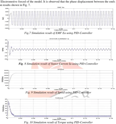
The Ea are the Electromotive forced of the model. It is observed that the phase displacement between the emfs are 120 degree. Their simulation results shown in Fig. 7.
Fig.7 Simulation result of EMF Ea using PID-Controller
Fig. 8 Simulation result of Stator Current Ia using PID-Controller
Fig. 9 Simulation result of Speed using PID-Controller
Fig. 10 Simulation result of Torque using PID-Controller
5.2 PERFOMANCE WITH GA CONTROLLER
Based on the system configuration shown in Fig. 5.9 the simulation of BLDC motor with GA tuned PID controller and current sensor loop is performed. The simulation result for reference speed input of 3000 RPM.This will helps to understand that GA is more efficient than the traditional methods.
IJEDR1504170
International Journal of Engineering Development and Research (www.ijedr.org)966
Fig. 12 Simulation result of Torque using GA-ControllerVI.CONCLUSION
The steady state error is approximately 5% but in the case of GA it is about 0.1%.We have seen that the in PID controller the overshoot is high and setting time take more time to settle down to overcome. So we can conclude from here that the tuning PID with soft computing techniques (GA) reduce manual error and also improve the performance dramatically. It can be seen that GA tuned system as compared to Ziegler-Nichols tuned system for PID, has less settling time and Rise time at no load condition.
FUTURE SCOPE
In future we shall improve transient state.
Steady state contains 0.01% harmonics, so we will try to implement with more advance heuristic algorithms. PSO can be implemented in future for better performance on loaded and unloaded condition.
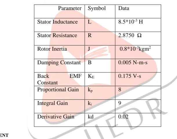
Table 1PARAMETERSOFTHE BLDC
Parameter Symbol Data
Stator Inductance L 8.5*10-3 H Stator Resistance R 2.8750 Ω Rotor Inertia J 0.8*10-3kgm2 Damping Constant B 0.005 N-m-s
Back EMF
Constant
KE 0.175 V-s
Proportional Gain kp 8
Integral Gain ki 9
Derivative Gain kd 0.02
VII.ACKNOWLEDGMENT
I would like to thank Mr. Santosh Rungta Sir Chairman, Dr. Sourabh Rngta Director(Voice Chairman), Mr. Sonal Rungta, Director(F&A), Dr. S.M. PRasanna (Director),Dr. S.P.Dubey, Dean, Mr. prasant Choudhary HOD Electrical department, R&D , of RCET Bhilai for his immense support and enlightened guidance.
REFERENCES
[1] T.J.E. Miller, “Brushless Permanent Magnet and Reluctance Motor Drives” Oxford Science Publication, UK, 1989.
[2] G.Prasad, N.Sree Ramya, P.V.N.Prasad, G.Tulasi Ram Das, “Modelling and Simulation Analysis of the Brushless DC Motor by using Matlab” ,(IJITEE) ISSN: 2278-3075, Volume-1, Issue-5, 2012.
[3] Purna Chandra Rao, Y. P. Obulesh and Ch. Sai Babu, “Mathematical modeling of BLDC motor with closed loop speed control using PID using controller under various loading conditions”, ARPN Journal of Engineering and Applied Sciences , vol. 7, no. 10, ISSN 1819-6608,2012.
[4] R. Krishna, “Electric Motor Drives -Modelling, Analysis and Control” Printice Hall, Inc., 2001.
[5] Pramod Pal, TM Shubhum and Dr. Amit Ojha, “Simulation of Brushless DC Motor for Performance Analysis using MATLAB/SIMULINK Environment”, ISSN: 2321-8169 Volume: 2 Issue: 6 1564 – 1567.
[6] José Carlos Gamazo-Real , Ernesto Vázquez-Sánchez and Jaime Gómez-Gil , “Position and Speed Control of Brushless DC Motors Using Sensorless Techniques and Application Trends” , ISSN 1424-8220,2010.