Available at
www.ijsred.com
Automation System for Electronic Devices Using IOT
San San Lwin, Win Win Maw
Lecturer, Department of Information Technology Engineering, Technological University, Kyaukse, Lecturer, Faculty of Computer System and Technologies University of Computer Studies, Mandalay,
Myanmar
---
************************
---Abstract:
Nowadays, the smart home technology is becoming popular in environment. Among these, the home appliances control using IoT is the most updated technology. Home appliances, such as light on and off, fan on and off and also air-con etc, can be turned on and off over mobile phones through internet. This system is explaining how to control designed circuit of two bulbs wirelessly but according to ones need one can connect any device (sensors, appliance etc, upto 8) to NodeMCU and can gain wireless control over it, with the help of this system, one can implement circuit and connect it with NodeMCU, program it accordingly with the help of Arduino and control device with the help of a Smartphone.
Keywords — transformer, bridge rectifier, LM323, ESP8266 Wi-Fi Module, single relay modules,
---
************************
---I. INTRODUCTION
Nowadays, it is faced the challenges of their science and technology improvement. The domestics and home system are automatically controlled with a lot of technology without manual. House automation is automation of the home or home activity. Home automation may include control of light, fans, appliances, and other systems, to provide more convenience, comfort, power cutting down and security. The idea of home automation has been evolved trough many years and products have recently been on the industry for long, though no person solution has broken before the popular yet. Home automation also helps for the aged and disables folks that have reached home as they need not move from one location to another place just for switching on or off the appliances, beginning the door, etc. That can also give a distant interface to home kitchen appliances or the automation system, over the internet, to provide control and monitoring via a smart phone or web browser. This system will describe system which the company is implementing to control various cookware with Arduino Ethernet, web server and google android smartphone.
II. COMPONENT OF THE SYSTEM
The proposed system consists of several main components. They are
1. Transformer 2. Bridge rectifier 3. Voltage regulator
4. Microcontroller 5. Relay Module
~
Vp
+
-+
-Vs
Np : Ns
Load
Figure: 2.1 Transformer
Figure: 2.2 Bridge Rectifier
Figure: 2.3 LM323
Figure: 2.4 ESP8266 Wi-Fi Module
Figure: 2.5 Single relay modules
III. OVERALL BLOCK DIAGRAM
DC 5V
ESP8266 NodeMCU Android Phone/PC
Relay 1
Relay 2
Relay 3
Relay 4
Light Bulb 1
Light Bulb 2
Light Bulb 3
Plug Socket
AC supply Cloud
(Thing Speak)
Cloud
Relay 5 Fan 1
Relay 6 Fan 2
Figure: 3.1 Block Diagram of the System
www.ijsred.com
START
Define I/O
Start Wi-Fi server
Read values from thingspeak
server
readvalue0=1?
Light 1 On
Light 1 OFF
readvalue1=1?
Light 2 On
Light 2 Off
readvalue2=1?
Light 3 On
Light 3 Off
readvalue3=1?
Light 4 On
Light 4 Off
A
Yes
Yes
Yes
Yes No
No
No
No
Figure: 3.2: Flowchart of the system (a)
A
readvalue4=1?
Fan 1 On
readvalue5=1?
Fan 2 On
Fan 2 Off
END
No
No
Yes
Yes
Fan 1 Off
Figure: 3.3 Flowchart of the system (b)
IV. RESULTS AND IMPLEMENTATION
4.1. Hardware Implementation
The overall prototype model of the system is shown in figure 4.1. This figure is the situation of before testing.
Figure: 4.2 System after activating
Figure: 4.3 Transformer used in the system
The stepdown transformer used in the system is shown in figure 4.3. The transformer (220 to 12) V is used in this system.
Figure: 4.4: Relay modules used in the system
The 8 channel relay used in the system is shown in figure 4.4.
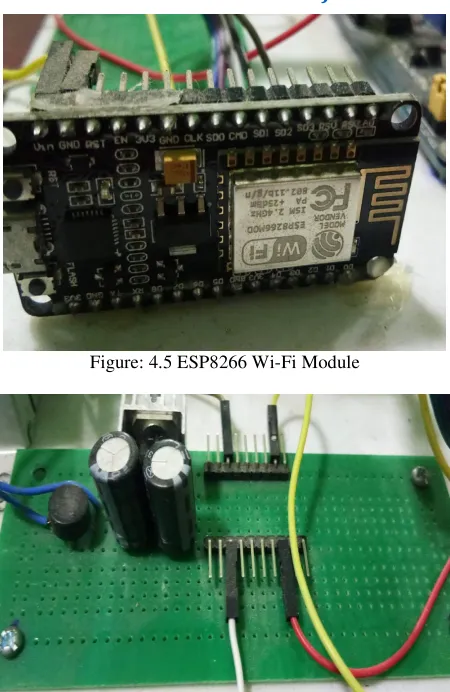
Figure: 4.5 ESP8266 Wi-Fi Module
Figure: 4.6: Power Supply Circuit of the system
Figure: 4.7 Thingspeak account
www.ijsred.com
Figure: 4.8 Button 1 field chart
Figure: 4.9 Button 2 Field Chart
Figure: 4.10 Button 3 Field Chart
Figure: 4.11 Button 4 Field Chart
Figure: 4.12 Button 5 Field Chart
4.2. Software Implementation
The software implementation is the Arduino IDE based software environment. A program written with the Arduino IDE is called a sketch. Sketches are saved on the development computer as text files with the file extension.
Arduino Software (IDE) pre-1.0 saved sketches with the extension.
A minimal Arduino C/C++ program consist of only two functions:
setup( ):
This function is called once when a sketch starts after power-up or reset. It is used to initialize variables, input and output pin modes, and other libraries needed in the sketch.
loop( ):
After setup( ) function exits (ends), the loop( ) function is executed repeatedly in the main program. It controls the board until the board is powered off or is reset.
4.6. Program Coding
Figure: 4.14 Wi-Fi service stating
Figure: 4.15 Defining I/O Pins
Figure: 4.16 Configuring the connection with the cloud server
Figure: 4.17 Controlling the Relay modules by using digital write
V. CONCLUSION AND DISCUSSIONS
5.1 CONCLUSION
This system presented a simple and flexible design for solar house monitoring and automation. The selected platform is the thingspeak that uses a cloud server to control the relays using the IoT principle. The NodeMCU combined with the ESP2866 was used as the main processing unit that collects the data from the sensors, processes it and then uploads it to the thingspeak cloud server. The NodeMCU can also read data and commands from the same server and control switching devices. This constitutes a complete smart-home monitoring and automation system that is based on the IoT technology. The proposed design of the smart home is very flexible and can be easily expanded and applied to larger buildings by increasing the number of sensors, measured parameters, and control devices. More functionality and smartness could be also added to the existing system for making the house automation system grow, adapt, and evolve by itself using advanced artificial intelligence.
5.2 DISCUSSIONS
www.ijsred.com
ACKNOWLEDGMENT
The author is very grateful to the committee of IJSRED and editorial board for permitting the study to publish. The author wishes to acknowledge the researchers and writers who wrote and created the journals, books and articles that are of great help to me for my journal. Without them, I would not think of any ideas and could not finish my journal successfully. .
REFERENCES
[1] SomayyaMadakam, R. Ramaswamy, SiddharthTripathi, “Internet of Things, (IoT): A Literature Review”, Journal of Computer and Communications, 2015,
[2] Internet of Things: Ubiquitous Home Control and Monitoring System using Android based Smart Phone at International Journal of Internet of Things 2013.
[3] SomayyaMadakam, R. Ramaswamy, SiddharthTripathi, “Internet of Things (IoT): A Literature Review”, Journal of Computer and Communications, 2015, 3,164-17
http://www.scirp.org/journal/jcc http://dx.doi.orghttp://dx.doi.org.
[4] Kosmatos, E.A., Tselikas, N.D. and Boucouvalas, A.C. (2011) Integrating RFIDs And Smart Objects into a Unified Internet of Things Architecture. Advances in Internet of Things: Scientific Research,
http://dx.doi.org/10.4236/ait. 2011.11002
[5] L. Atzori, A. Iera, G. Morabito, The Internet of Things: A survey, Computer Networks5 (2010) 2787–2805.
[6] M. Wu, T. J. Lu, F. Y. Ling, J. Sun, and H. Y. Du, “Research on the architecture of Internet of Things,” in Proc. 3rd ICACTE, 2010, pp. V5-484–V5-487.
[7] Biddlecombe, E. (2009) UN Predicts “Internet of Things”. Retrieved July 6.
[8]http://www.sciencedirect.com/science/article/pii/ S0167739X13000241
[9]https://standards.ieee.org/develop/wg/ IoT_Architecture.html