Optimum sliding mode controller design based on skyhook
model for nonlinear vehicle vibration model
M. Salehpour, A. Jamali*, A. Bagheri, N. Nariman-zadeh
Faculty of Mechanical Engineering, University of Guilan, Rasht, Iran. P.O. Box: 3756,
[email protected] Abstract
In this paper a new type of multi-objective differential evolution employing dynamically tunable mutation factor is used to optimally design non-linear vehicle model. In this way, non-dominated sorting algorithm with crowding distance criterion are combined to fuziified mutation differential evolution to construct multi-objective algorithm to solve the problem. In order to achieve fuzzified mutation factor, two inputs as generation number and population diversity and one output as the mutation factor are used in the fuzzy inference system. The objective functions optimized simultaneously are namely, vertical acceleration of sprung mass, relative displacement between sprung mass and unsprung mass and control force. Optimization processes have been done in two bi- and three objective areas. Comparison of the obtained results with those in the literature has shown the superiority of the proposed method of this work. Further, it has been shown that the results of 3-objective optimization include those of bi-objective one, and therefore it gives more optimum options to the designer.
Keywords: non-linear vehicle model, Pareto, Multi-objective optimization, Differential evolution, Fuzzified mutation
1. Introduction
Suspension system in a typical vehicle is a significant part which affects ride comfort and road holding capability considerably [1]. Generally speaking, there are three types of suspension systems which are namely, passive, semi-active and active [1-3].
Passive suspension is composed of parallel installation of spring and damper between the vehicle body (sprung mass) and wheel-axle assembly (unsprung mass) [2-3]. Active suspension needs an external power source which supplies control force to improve the passive components [3-4]. Semi-active one is in-between the two aforementioned suspensions. This kind of suspension dissipates low level of energy [3] and with its varying damping properties can achieve a better performance than passive one [2]. Active suspensions offer appreciable behavior under different road excitations in comparison with passive and semi-active ones [2, 4]. Therefore several control approaches have been proposed by the researchers in the field of the design of the active suspension such as, optimal control [5], preview control [6], robust control [7-8], neural
networks [9], back-stepping control [2], fuzzy control [10-11] and so forth.
Model reference is used to have a real suspension plant go along it [12]. For this purpose, skyhook model has been employed by some authors [13-15] as a theoretical reference model.
Sliding mode control is a useful method to design systems which are robust to external disturbances or parameters uncertainties. It can provide invariability if the bounds of variations are clear and the sliding condition is fulfilled [16]. By choosing a proper sliding surface the appropriate dynamic performance of the system can be achieved [12]. Kim and Ro [17] proposed a method based on the combination of sliding mode control and skyhook model to design active suspensions considering non-linearites.
It should be noted that finding an exact model of a real suspension plant and acceptable estimation of road irregularities are complicated tasks. On the other hand, in the sliding mode control design, the system with uncertainties and disturbances can be stabilized if the bounds of them are plain. Since, road irregularities may change considerably, achieving such bounds seems a difficult task. In order to overcome this shortage, in [12] inertial delay control method has been used to estimate the non-linearities
of suspension system and the outcome of unknown road disturbance.
It is important to notice that there is a good competence to employ global optimization methods for the design of vehicle suspension system [18]. As a matter of fact, there are considerable differences between evolutionary algorithms (EAs) and gradient based optimization method. The performance of gradient based method largely depends on the starting point and the direction of the gradient. Therefore, there is a high probability to get trapped in the local optima [19]. But, in case of EAs, because of the stochastic population based nature of them, the search direction can be changed in such a way to escape the local optima and approach towards the global ones [20]. The nature of EAs qualify them to be used in the multi-objective optimization problems (MOPs). Actually, in MOPs, there are some objective functions which conflict together. Therefore, if one of them improves the other one deteriorates and vice versa. Consequently, there is no unique solution and a set of solutions named Pareto front [21].
There are two principal targets in the optimization process by the EAs [22]:
1. Directing the search process to the true Pareto curve
2. Preventing premature convergence or persevering population diversity
Pareto optimal design of vehicle vibration model can achieve an acceptable trade-off between ride comfort and road holding capability as can be seen in [8, 21, 23-24].
In this paper one of the newly developed methods of EAs named differential evolution [25-26] is used to optimally design the active suspension model [12]. DE is a fast and robust algorithm [27-28]. Further, its performance is considerably dependent on two significant factors, namely mutation and crossover [29-31].
As reported in the literature, high value of mutation factor is effective in global search but low value of that may hasten the convergence speed. Besides, the larger value of crossover probability may increase the diversity of the population but the lower one of that improve the local exploitation [31]. So, tuning the aforesaid factors can improve the performance of DE. In this paper, fuzzy logic [32] is employed to dynamically adjust the mutation factor of DE. In this way, papers such as [33-34] have been done based on the hybrid usage of fuzzy logic and DE to dynamically adapt the mutation factor.
In this paper, a multi-objective differential evolution with dynamically adaptable mutation factor [34] is employed for Pareto optimal design of an
active vehicle suspension model [12]. The conflicting objective functions have been chosen as vertical acceleration of sprung mass, relative displacement between sprung mass and unsprung mass, and control force. Furthermore, design variables are chosen as the two important effective factors on the control procedure which will be described later. Multi-objective optimization has been done in 2- and 3-objective areas. Comparison of the obtained results with those in the literature proves the superiority of the results of this work.
2. Multi-objective Fuzzified Differential Evolution (MFDE)
In general, multi-objective optimization problems (MOPs) can be described as follows [21-22]:
Finding the best set of design variables :
to optimize the set of objective functions :
by satisfying m inequality constraints:
and p equality constraints:
where and .
It means that a set of objective functions must either be minimized or maximized. But, in case of maximization by multiplying equation (2) by , the problem can be converted into minimization without loss of generality [27]. The respectful reader may refer to [21-22] for more information about Pareto dominance, Pareto optimality, Pareto set and Pareto front.
In differential evolution (DE), two operators, namely, mutation and crossover are exerted to the parents, respectively, to produce offsprings as follows [34]:
( )
( )
in which, n, G, d, , and along with indicate, number of population, number of generation, number of dimension of the search space, mutation factor, two randomly selected disparate vectors and the vector which is randomly selected from the first front of the last generation so far [35], respectively.
M. Salehpour, A. Jamali, A. Bagheri, N. Nariman-zadeh 2539 { (7)
where, is a number randomly chosen from [0, 1]; is employed in equation (7) to insure that
and represents crossover probability.
Parents and offsprings are joined together using non-dominated sorting algorithm [36] and crowding distance criterion [36]. The results enter to the next generation and the optimization process reiterates.
When algorithm is started by the operator, the initial population is generated randomly. So, this randomly produced population is used as the parents at this time. But, in the next generation, parents are the ones who have entered from the previous generation. And the process goes on.
The goal of the non-dominated sorting algorithm is to assign rank to each individual of the population by comparing it to the others. If the individual dominates them or are non-dominated to them, they enters to the first rank to form first Pareto front. After constructing first rank, the individuals in it are deleted from the population and this process repeats for the remainder of the population to construct other Pareto frontiers.
The purpose of crowding distance criterion is to avoid dense crowding of population in a limited zone to conserve the diversity of the population. In order to achieve this goal, crowding distance criterion appoints a value to each member as the crowding criterion to show the average distance of it with respect to the others. Each members with higher crowding criterion has the higher chance to go to the next generation.
The respectful reader may refer to [36] to find more information about non-dominated sorting algorithm and crowding distance criterion.
As discussed earlier, DE is a swift and robust algorithm, but is has some drawbacks. Although DE is good at global search, it is weak in local search [37]. DE has trouble with premature convergence and population stagnation [38]. Its performance is mostly influenced by its operators (such as mutation factor and crossover probability), therefore in different conditions it may cause difficulty [39].
To overcome the above-mentioned deficiencies, fuzzy logic [32] is employed to dynamically adapt the mutation factor considering two significant parameters mentioned as follows [34]:
1. Number of generation 2. Population diversity
As far as in low number of generation, algorithm needs to find the limitation of global optimum (optima), large step seems proper. As a result, high value of mutation factor may be better. On the other hand, in high number of generation, low value of mutation factor is good to exploit through the search space. Such logic can be used for the population diversity, too. Actually, when population packs together (low value of diversity), low value of mutation factor can be efficacious for fine-tuning through the population. Further, when population diversity is high, larger value of mutation factor may be useful [34].
Consequently, in this work, fuzzy logic considering two significant above-mentioned parameters as inputs, and one output as mutation factor, is used to improve the performance of the differential evolution algorithm. Fuzzy rules employed here are depicted in table 1 [34].
Briefly speaking, fuzzfied mutation obtained here is used in equation (6) instead of conventional one, and the remainder of the procedure carries out as discussed earlier. This methodology is called multi-objective fuzzified differential evolution (MFDE) and applied to Pareto optimal design of active suspension model [12]. The aforementioned methodology is presented in figure 1.
3. Two degree of freedom nonlinear vehicle vibration model
The vehicle model employed here is depicted in figure 2 [12]. The equations of suspension system can be shown as:
̈
̈
where , , , and display nominal sprung mass, nominal unsprung mass, vertical displacement of the sprung mass in relation to its static position, vertical displacement of the unsprung mass in relation to its static position and control force, respectively. Furthermore, ̇ ̇ {
in which, , and are constants and is the relative displacement between sprung and unsprung mass. Besides, is the gravity acceleration.
Supposing , ̇ , and
̇ , the state equations of motion can be written as follows:
̇
̇
̇
̇
The aforementioned vehicle model is excited by two road inputs as:
Case 1 [12]:
Case 2 [12]:
These two road profiles are displayed in figures 3-4, respectively.
Fig1.Schematic diagram of the proposed methodology.
Fig2.Non-linear vehicle model [12].
M. Salehpour, A. Jamali, A. Bagheri, N. Nariman-zadeh 2541
Fig3.Road input case 1 [12].
Fig4.Road input case 2 [12].
Table 1. Fuzzy rule-based system used here [34]
Output of fuzzy system is Mutation Factor
Diversity
Low Medium High
Number of Generation
Low (…) Medium (…) High (…) Very High
Medium (…) Low (…) Medium (…) High
High (…) Very Low (…) Low (…) Medium
(…): Mutation Factor must be
3.1 The skyhook reference model
The popular conceptual skyh
+
ook model is seen in figure 5 [12, 17]. It is important to notice that since the tire is about ten times stiffer than the suspension spring, it is possible to approximate road input with the displacement of the unsprung mass (more information can be found in [17]). Therefore the equation of motion of the skyhook model can be written as follows [12]:̈ ̇ ̇ ̇
since :
̈ ̇ ̇
Whrere , , , , , , and
are, namely, skyhook linear damper coefficient, sprung mass, unsprung mass, linear spring coefficient, linear damper coefficient, vertical displacement of the sprung mass of the skyhook reference model in relation to its static position and vertical displacement of the unsprung mass of the skyhook reference model in relation to its static position.
3.2The sliding surface and control design
When the sliding happens, the system precedes the skyhook model. By selecting sliding surface, the controller is modeled [12].
Therefore, the sliding surface is chosen as:
where
̇
[
]
By using equation (21), reaching phase is deleted. Variable helps the system follow the reference model [12].
Control force, , is divided into two parts, namely,
and to deal with known terms and uncertainty,
respectively.
Differentiating equation (21) gets:
̇
[
̇ ]
By defining lumped uncertainty as , the above equation can be written as:
̇
[
]
In fact, is defined based on the uncertainty and road disturbance.
As talked before,
in which,
[
]
where is positive.
Therefore equation (24) is written as follow:
̇
It is supposed that:
̂
in which ̂ is the estimation of the uncertainty . As a result:
̇ ̂
The estimation error can be defined as:
̃ ̂
Substituting equation (30) into (29) yields:
̇ ̃
The key idea in control is to use the system information in the recent past to obtain an estimate of the uncertainty and then to use the opposite of it in control to negate the effect of the uncertainty.
In inertial delay control (IDC), the data of the recent past of the system is employed to achieve an estimation of the uncertainty. Then the opposite of that is used in control design to nullify the effect of the uncertainty [12].
̃
in which is a first order filter defined as:
where is a positive and small constant. By observing equation (31), it can be written as:
̇ ̃
Substituting equation (32) in (33) and the result in (34) gives:
̂ ∫
Performing the same procedure for equation (30) yields:
̃̇ ̃ ̇
If ̇ , ̃ converges to zero asymptotically. If not, it is ultimately bounded. The respectful reader for more information about the IDC-based control and the stability proof may refer to [12].
4. Multi-objective Pareto optimization of a non-linear vehicle model using multi-objective differential evolution with fuzzified mutation
In this section, multi-objective optimization of a non-linear vehicle model [12] based on the methodology proposed here has been done. The
M. Salehpour, A. Jamali, A. Bagheri, N. Nariman-zadeh 2543
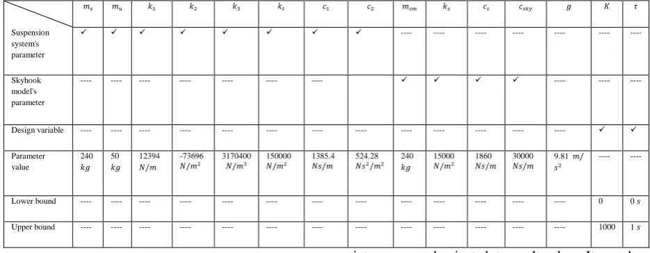
objective functions used here to be minimized simultaneously, are, namely, vertical acceleration of sprung mass ̈ ( ) , relative displacement between sprung and unsprung mass , and control force ( ). The design variables are chosen as the factors effective on the control procedure design indicted by and . The optimal design process has been done in two areas which are bi- and 3-objective optimization. The values of fixed parameters and the bounds of design variables are shown in table 2.
4-1 Bi-objective optimization of the non-linear vehicle vibration model
In this subsection, two different pairs out of three possible pairs of objective as ̈ and ̈ are used to be minimized separately. A population of 80 individuals with 240 generations are employed to optimally design the vehicle model using a crossover probability of 0.9 and the fuzzified adaptable mutation factor discussed earlier [34] in two optimization processes separately for two road profiles. The obtained Pareto fronts are shown in figures 6-9. As readily seen through these figures, improving one of the objective functions leads to deteriorating the other one and vice versa. It means that choosing a set of objectives based on the Pareto
fronts equals to the best possible couple of them. On the other hand, the couple which do not follow the mentioned rule, locate the point inferior to the Pareto fronts. Such locations are in the top/right sides of the figures 6-9.
In the Pareto font curves, points , and are the points with the significant optimal concept. As easily seen in figures 6 and 8, points and show considerable improvements in ̈ in comparison with and (the points having lowest values in ), but negligible deterioration in . The same comparison between and with and , in figures 7 and 9, shows worthwhile improvements in control force, but trivial increase in other objective. Therefore, points , and are trade-off points in the their related Pareto frontiers. Further, point (suggested by [12]) locate in the top/right sides (inferior area) of figures 6, 8-9 and the Pareto fronts are superior to it. Besides in figure 7, the Pareto front includes point , and as a result this point is non-dominated to the others in the curve. The values of objective functions and their associated design variables of points
, , , , , , , and are depicted in table 3.
Briefly, bi-objective optimization offers several optimal solutions which can be used by the designer. But, more optimal choices can be obtained by the 3-objective optimization simultaneously described in the next subsection.
Fig5.Conceptual skyhook model [12].
Fig6.Pareto front of vertical sprung mass acceleration and relative displacement between sprung and unspring mass resulted by bi-objective optimization for case 1.
Fig7.Pareto front of vertical sprung mass acceleration and control force resulted by bi-objective optimization for case 1.
Fig8.Pareto front of vertical sprung mass acceleration and relative displacement between sprung and unspring mass resulted by bi-objective optimization for case 2.
M. Salehpour, A. Jamali, A. Bagheri, N. Nariman-zadeh 2545
Fig9.Pareto front of vertical sprung mass acceleration and control force resulted by bi-objective optimization for case 2.
Table 2. The values of fixed parameters and the bounds of design variables
Suspension system's parameter
---- ---- ---- ---- ---- ---- ----
Skyhook model's parameter
---- ---- ---- ---- ---- ---- ---- ---- ---- ----
Design variable ---- ---- ---- ---- ---- ---- ---- ---- ---- ---- ---- ---- ----
Parameter value
240
50
12394
-73696
3170400 150000 1385.4 524.28 240 15000
1860 30000 9.81
---- ----
Lower bound ---- ---- ---- ---- ---- ---- ---- ---- ---- ---- ---- ---- ---- 0 0
Upper bound ---- ---- ---- ---- ---- ---- ---- ---- ---- ---- ---- ---- ---- 1000 1
4-2 three-objective optimization of the non-linear vehicle vibration model
In this subsection, a 3-objective optimization instead of two separate bi-objective optimization (for each road input) has been done. All of the three objective are used together to be optimized simultaneously. A population of 80 individuals with 240 generations are adopted to optimally design the vehicle model using a crossover probability of 0.9 and the fuzzified adaptable mutation factor described earlier [34] for each road profile.
Pareto fronts for each road inputs are depicted in figures 10-13. It seems that some points are in these figures which dominate others. But, when observed from the view of all three objective, all optimum
points are non-dominated to each other. It can be readily seen through the figures that the results of 3-objective subsume the ones of bi-objective optimizations. In fact, the Pareto fronts achieved by bi-objective optimizations form the bounding lines of each planes obtained by the 3-objective optimization in such a way that no solution exits superior to such borderlines.
It is time to propose a point as the trade-off one from the view of all the objective functions. Points and are chosen as the trade-offs amongst all the optimum points due to using control force in the suspension system. As a matter of fact, employing such force helps suspension system have proper ̈ . Therefore, reaching a solution having lowest value of
̈ considering the control force may play the role of the trade-off design point. Of course, there are several
points in each plane with different characteristics that can be used by the designer in various conditions. As a matter of fact, such kind of multi-objective optimization give a wide range of area of optimum modeling to the designer to use for the proper condition.
Time response behaviors of the points , and are presented in figures 14-15. Based on the table 3, it can be found that the area covered under the curves
resulted by and are lower than the one of point . This fact shows the improvement in the values of vertical acceleration of sprung mass by using methodology of this work.
Whatever discussed earlier, in this and former subsection, proves the superiority of the proposed method of this work. In fact, the results obtained here would not have been found without the use of Pareto optimization procedure of this work.
Table 3. values of the objective functions and their associated values of design variables of optimum points of this work / the one of [12]
̈ ( )
18.24123 0.054834 1.39266 0.203785 4291.759
10.09178 0.099094 0.543047 0.22691 4054.901
3.024461 0.340162 2.454501 0.195222 4154.106
0.025427 0.999517 1.399673 0.204075 4286.258
0.91846 0.999525 0.999312 0.204473 3532.692
0.503078 0.999139 1.01779 0.204785 3526.25
12.83386 0.061148 1.425465 0.202871 4299.880
66.72541 0.075006 1.466695 0.204431 4263.94
7.951234 0.119386 0.548142 0.22565 4029.499
7.878231 0.136905 0.553127 0.225080 4017.729
200 0.01 1.49858 0.204526 4247.061
200 0.01 0.567434 0.228246 4080.086
: Point in case 1, : Point in case 2.
Fig10. Pareto front of vertical sprung mass acceleration and relative displacement between sprung and unsprung mass resulted by 3-objective optimization for case 1.
M. Salehpour, A. Jamali, A. Bagheri, N. Nariman-zadeh 2547
Fig11. Pareto front of vertical sprung mass acceleration and control force resulted by 3-objective optimization for case 1.
Fig12. Pareto front of vertical sprung mass acceleration and relative displacement between sprung and unsprung mass resulted by 3-objective optimization for case 2.
Fig13. Pareto front of vertical sprung mass acceleration and control force resulted by 3-objective optimization for case 2.
Fig14. Comparison of time response behaviors of vertical sprung mass acceleration obtained by point (this work) and [12].
Fig15. Comparison of time response behaviors of vertical sprung mass acceleration obtained by point (this work) and [12].
5- Conclusion
A new version of multi-objective differential evolution with fuzzified mutation is applied to optimally design non-linear vehicle model excited by two different road profiles. Fuzzy inference system is employed to dynamically adapt the mutation factor using generation number and population diversity as inputs and mutation factor as output to construct nine-rule fuzzy model. Three objective functions are chosen to be optimized simultaneously, and are, namely, vertical sprung mass acceleration, relative displacement between sprung and unsprang mass and control force. The optimization processes have been done both in 2- and 3-objective area in terms of Pareto frontiers. Some important trade-offs have been found through the Pareto optimal design. Further, it has been shown that the results of 3-objectve optimization contains those of 2-objectve. In fact the results of bi-objective optimization locate on the boundary of the ones of 3-objective optimization, and it can provide more optimal choices for the designers. Further, comparison of the results of this work with those in the in the literature has been shown the
superiority of the proposed methodology of this paper.
References
[1]. S. Chen, J. Wang, M. Yao, Y. Kim, Improved optimal sliding mode control for a non-linear vehicle active suspension system, 395 (2017) 1-25.
[2]. N. Yagiz, Y. Hacioglu, Backstepping control of a vehicle with active suspensions, Control Engineering Practice 16 (2008) 1457–1467. [3]. M. Bouazara, M. Richard, An optimization
method designed to improve 3-D vehicle comfort and road holding capability through the use of active and semi-active suspensions, European Journal of Mechanics-A/Solids, 20 (2001) 509–520.
[4]. S. Liu, H. Zhou, X. Luo, J. Xiao, Adaptive sliding fault tolerant control for nonlinear uncertain active suspension systems, Journal oftheFranklinInstitute353(2016)180–199. [5]. R. Mendoza, M. Nawarecki, O. Sename, L.
Dugard, M. M'Saad, An optimal control approach for the design of an active suspension
M. Salehpour, A. Jamali, A. Bagheri, N. Nariman-zadeh 2549
[6]. system, IFAC Proceedings Volumes, 31 (1) (1998) 43-48.
[7]. J. Marzbanrad, G. Ahmadi, H. Zohoor, Y. Hojjat, Stochastic optimal preview control of a vehicle suspension, Journal of Sound and Vibration 275 (2004) 973–990.
[8]. B. Sepehri, A.Hemati, Active Suspension vibration control using Linear H-Infinity and optimal control, International Journal of Automotive Engineering, 4 (2014) 805-811. [9]. A. Jamali, M. Salehpour, N. Nariman-zadeh,
Robust Pareto active suspension design for vehicle vibration model with probabilistic uncertain parameters, Multibody System Dynamics, Vol. 30, No. 3, pp. 265-285, 2013. [10]. K. Spentzas, S. Kanarachos, Design of a
non-linear hybrid car suspension system using neural networks, Mathematics and Computers in Simulation 60 (2002) 369–378.
[11]. F. D'Amato, D. Viassolo, Fuzzy control for active suspensions, Mechatronics 10 (2000) 897-920.
[12]. B. Cai, D. Konik, Intelligent vehicle active suspension control using fuzzy logic, IFAC Proceedings Volumes, 26 (2) (1993) 51-56. [13]. V. Deshpande1, P. Shendge, S. Phadke, Active
suspension systems for vehicles based on a sliding-mode controller in combination with inertial delay control, Proceedings of the Institution of Mechanical Engineers, Part D: Journal of Automobile Engineering, 227 (5) (2013) 675-690.
[14]. A. Tiwari, M. Lathkar2, P. Shendge, S. Phadke, Skyhook control for active suspension system of heavy duty vehicles using inertial delay control, Power Electronics, Intelligent Control and Energy Systems (ICPEICES),IEEE International Conference on, (2017) 1-6. [15]. A.Turnip, I. Setiawan, M. Amri, T. Tamba,
Controller design for active suspension system based on skyhook reference model, Technology, Informatics, Management, Engineering & Environment (TIME-E), 2015 International Conference on, (2015) 147-151. [16]. T. Yoshimura, Y. Isari, Q. Li, J. Hino, Active
suspension of motor coaches using skyhook damper and fuzzy logic control, Control Engineering Practice, 5(2)(1997) 175-184. [17]. J. Slotine, Sliding controller design for
non-linear systems,
International Journal of Control, 40 (2) (1984) 421-434.
[18]. C. Kim, P. I. Ro, A sliding mode controller for vehicle active suspension systems with non-linearities, Proceedings of the Institution of
Mechanical Engineers, Part D: Journal of Automobile Engineering, 212 (2) (1998) 79-92. [19]. A.E. Baumal, J.J. McPhee, P.H. Calamai,
Application of genetic algorithms to the design optimization of an active vehicle suspension system, Computer methods in applied mechanics and engineering, 163 (1998) 87-94. [20]. G. Renner, A. Ekárt, Genetic algorithms in
computer aided design, Computer-Aided Design, Vol. 35, No. 8, pp 709-726, 2003. [21]. S. Kitayama, M. Arakawab, K. Yamazaki,
Differential evolution as the global optimization technique and its application to structural optimization, Applied Soft Computing 11 (2011) 3792–3803.
[22]. N. Nariman-Zadeh, M.Salehpour, A.Jamali, E.Haghgoo, Pareto optimization of a five degree of freedom vehicle vibration model using a multi-objective uniform-diversity genetic algorithm (MUGA), Engineering Applications of Artificial Intelligence, Vol. 23, No. 54, pp. 543–551, 2010.
[23]. A. Toffolo, E. Benini, Genetic Diversity as an Objective in Multi-Objective Evolutionary Algorithms, Evolutionary Computation, 11 (2) (2003) 151-167.
[24]. M. Salehpour, A. Jamali, N. Nariman-zadeh, Optimal selection of active suspension parameters using artificial intelligence, International Journal of Automotive Engineering, 1 (2011) 244-255.
[25]. M.J. Mahmoodabadi A. Adljooy Safaie, A. Bagheri, N. Nariman-zadeh, A novel combination of Particle Swarm Optimization and Genetic Algorithm for Pareto optimal design of a five-degree of freedom vehicle vibration model, Applied Soft Computing, 13 ( 5) (2013) 2577–2591.
[26]. R. Storn, K. Price, Differential evolution: a simple and efficient adaptive scheme for global optimization over continuous spaces. Technical report TR-95-012. Berkeley (USA): International Computer Science Institute; 1995. [27]. R. Storn, K. Price, Differential evolution-a
simple and efficient heuristic for global optimization over continuous spaces, Journal of Global Optimization, 11(4) (1997) 341–59. [28]. L. Coelho, T. Bora, V. Mariani, Differential
evolution based on truncated Lévy-type flights and population diversity measure to solve economic load dispatch problems, Electrical Power and Energy Systems 57 (2014) 178–188. [29]. J. Vesterstrom, R. Thomsen, A Comparative
Study of Differential Evolution, Particle Swarm Optimization, and Evolutionary Algorithms on
[30]. Numerical Benchmark Problems, Congress on Evolutionary Computation 2 (2004) 1980 -1987. [31]. D. Zaharie, Influence of crossover on the behavior of Differential Evolution Algorithms, Applied Soft Computing, 9 ( 3) (2009) 1126– 1138.
[32]. M. Asafuddoula, T. Ray, R. Sarker, An adaptive hybrid differential evolution algorithm for single objective optimization, Applied Mathematics and Computation 231 (2014) 601– 618.
[33]. Y. Wang, H. Li, T. Huang, L. Li, Differential evolution based on covariance matrix learning and bimodal distribution parameter setting, Applied Soft Computing 18 (2014) 232–247. [34]. L. A. Zadeh, Fuzzy Sets, Information and
Control 8 (1965) 338-353.
[35]. P. Ochoa, O. Castillo, J. Soria, Differential Evolution with Dynamic Adaptation of Parameters for the Optimization of Fuzzy Controllers, O. Castillo,P. Melin (Eds.), Fuzzy Logic Augmentation of Nature-Inspired Optimization Metaheuristics, Studies in Computational Intelligence, Theory and Applications, Springer International Publishing Switzerland, 574 (2015) 49-63.
[36]. M. Salehpour, A. Jamali, A. Bagheri, N. Nariman-zadeh, A new adaptive differential evolution optimization algorithm based on fuzzy inference system, Engineering Science and Technology, an International Journal, 20 (2) (2017) 587–597.
[37]. I. Gholaminezhad, A. Jamali, A multi-objective differential evolution approach based on ε-elimination uniform-diversity for mechanism design, Structural and Multidisciplinary Optimization, 52 (5) (2015) 861–877.
[38]. K. Deb, A. Pratap, S. Agarwal, A fast and elitist multiobjective genetic algorithm: NSGA-II, IEEE Transactions on Evolutionary Computation, 6 (2) (2002) 182-197.
[39]. N. Noman, H. Iba, Accelerating Differential Evolution Using an Adaptive Local Search, IEEE Transactions on Evolutionary Computation 12 (2008) 107-125.
[40]. J. Lampinen, I. Zelinka, On Stagnation of the Differential Evolution Algorithm, 6th international conference on soft computing MENDEL 2000, Brno, Czech Republic, June 7-9, 2000, 76-83, ISBN 80-214-1609-2.
[41]. A. W. Mohamed, RDEL: Restart Differential Evolution algorithm with Local Search Mutation for global numerical optimization, Egyptian Informatics Journal 15 (2014) 175– 188.
![Table 3. values of the objective functions and their associated values of design variables of optimum points of this work / the one of [12]](https://thumb-us.123doks.com/thumbv2/123dok_us/8949460.1858828/10.595.165.418.255.527/table-values-objective-functions-associated-values-variables-optimum.webp)
