Roll Stability Early Warning System
Based on Tilt Sensor
https://doi.org/10.3991/ijoe.v13i09.7586
Jingmei Zhang
Beijing Jiaotong University, Beijing, China
Hebei University of Science and Technology, Shijiazhuang, China [email protected]
Abstract—In view of the over-speed phenomenon of heavy haul vehicles at high speed, the estimation of the effective range of the dynamic stability and in-clination angle of the truck was carried out a rollover stability alarm system based on liquid pendulum angle sensor and virtual instrument software was de-veloped. The working principle and data processing module of tilt sensor are discussed, through the data lines to output analog voltage signal transmitted to the vehicle electronic control unit. A control command is sent by the electronic control unit and sent to the driver via an alarm device, which enables the driver to control the speed in time, and so it reduces the risk of a rollover accident. The results show that the warning system is of good accuracy. The early warn-ing system preventwarn-ing malignant road traffic accidents has important social sig-nificance and actual application value for a safe vehicle.
Keywords—Heavy vehicle, tilt sensor, warning system, roll angle
1
Introduction
In the transportation industry, the heavy use of heavy vehicles has improved the transportation efficiency and produced huge economic benefits, but the ensuing secu-rity problems have become increasingly prominent. Rollover yearly caused a large number of casualties and property losses, which is the main safety problem of heavy vehicles. The investigation into accidents caused by automobile shows that a serious accident occurred in the number of vehicle rollover vehicle accounted for about 1/3 of the total number of vehicle traffic accident. Thus, the transportation safety problem of operating vehicle has become one of the key problems to be solved urgently.
weight distribution, or even turn into a little, the heavy vehicle will have a pro-nounced tendency to roll under heavy braking.
Vehicle safety monitoring and warning technology in many countries as a basic re-search is put a lot of effort. A series of rere-searches have been carried out on the devel-opment of vehicle monitoring and warning device. Developed countries also carry out a number of major projects in vehicle safety. Such as the US VII project and the CVHAS project, Japan's ASV, smart way and AHS projects, the European e safety program and so on the vehicle monitoring and warning device is one of the key re-search projects. After years of rere-search, the multi vehicle safety auxiliary driving device developed by developed countries has gradually entered the practical process [1].
Study on the safety of road transport and the transport of dangerous goods in China started late, technology level is relatively backward. Roll stability control system of Ford automobile company is one of the mature products [2] [3], which uses sensors to monitor car roll dynamics. It uses a controller to allocate braking power to reduce the lateral tire force when the car rollover trend [4]. BOSCH (Bosch)'s proprietary elec-tronic body stabilizing system is configured mainly in the high-end car and less in heavy vehicles.
An early warning system of roll stability for vehicle is developed against the rollo-ver accident. A tilt sensor is arranged on the longitudinal symmetrical surface of the frame of the vehicle. The tilt change signal is out-put to the ECU system, and before or after driving and braking forces around the wheel are controlled by ECU. And the driver is warned to lower the speed. The lateral stability of the vehicle is improved to the maximum. Eventually reduce the possibility of car rollover.
2
Roll monitoring and warning system
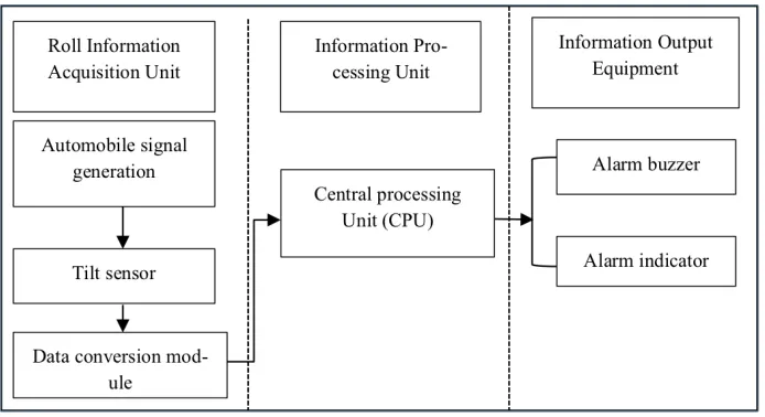
The overall structure of the vehicle roll monitoring and warning system of this study include three parts: roll information acquisition unit, information processing unit and Information output equipment. The roll information acquisition unit is main-ly composed of a signal generator, tilt sensor and data conversion module; the infor-mation output device comprises an alarm buzzer and an alarm indicator lamp as shown in Figure 1.
3
Tilt sensor
3.1 Working principle
The theoretical basis of the tilt angle sensor is Newton's second law; its core is the "liquid pendulum" type inertial device.
Fig. 1. Block diagram of roll warning system
a) b) Fig. 2. Schematic diagram of sensor
Conductive liquid adopts a novel conductive additive for LIB—a new high per-formance lithium ion conductive agent, it can increase the capacity, lower the IR, improve the rate, cycling life, high & low temperature performance and safety per-formance.
3.2 Data conversion module
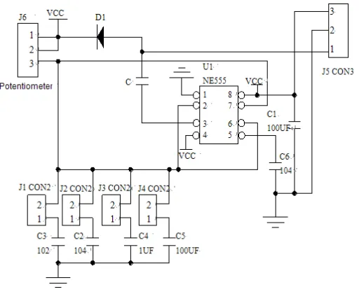
The sensor charge is tilted due to the tilting of the vehicle, which result in a change in the liquid resistance. So the change of angle is changed into linear resistance. The analog voltage output is output through the circuit. Fig. 3 is the circuit for sensor data conversion module. The circuit is composed of two parts: the square wave signal generator and the indicating circuit. A square wave signal generator based on NE555 chip as the core. In the third feet square of NE555 the wave signal is output. After the C terminal is connected with the capacitance to be measured, the square wave signal is repeatedly charged and discharged with the measuring capacitor. If the time con-stant of the charge discharge circuit is much smaller than the period of the square wave signal, the average value of the charging current or discharge current is directly proportional to C. The charge discharge current of the capacitor is rectified by D1 to be the average voltage of charging, and it is shown by potentiometer, therefor the potentiometer indications that reflect the vehicle roll angle size.
Fig. 3. Data conversion module of tilt sensor
4
Experimental data processing and error analysis
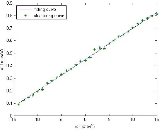
The output voltage of the sensor by simulation, the relationship between the output voltage and the dip angle is experimentally measured, as shown in Fig. 4. Curve fit-ting using least square method according to actual measured output voltage. A linear fitting curve is obtained:
!! ! !!!!"#! ! !!!" (1)
It can be seen that the results are very close by comparing the two curves, and the linear mean error is only 0.012%.
Fig. 4. Fitting curve and measuring curve
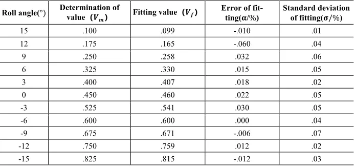
With a tilt angle of 3 degrees change rate, each tests 5 times, the average !! is
tak-en as the measuring value of the voltage. According to Eq. (1), the voltage fitting value of the same dip angle !! is obtained. The fitting error and the standard deviation
of measured value and fitted value are calculated. Fitting error:
! ! !!!! !!!!!! (2)
Standard deviation:
! ! !!!!!!!!!!!!
! (3)
The average value of fitting error is 0.014%, the average value of the standard de-viation of the fitting is 0.04%according to Table 1. In the range of side inclination
from!!"!!"!"!, the measurement accuracy for roll sensor is !!!"! and the sensitivity
is!!!!"#!!"#$%.
Table 1. Data and errors
Roll angle(!! Determination of value!!!" Fitting value!!!" Error of fit-ting(!/!) Standard deviation of fitting(!!!)
15 .100 .099 -.010 .01
12 .175 .165 -.060 .04
9 .250 .258 .032 .06
6 .325 .330 .015 .05
3 .400 .407 .018 .02
0 .450 .460 .022 .05
-3 .525 .541 .030 .05
-6 .600 .600 .000 .04
-9 .675 .671 -.006 .07
-12 .750 .759 .012 .02
-15 .825 .815 -.012 .03
5
Selection of the tilt sensor mounting position
5.1 Analysis of factors affecting rollover
The load is mainly concentrated in the carriage for heavy duty vehicles. The vehi-cle carriage rolls firstly at most of the time. Then the cab does that along with it. Tak-ing the three axle 25 ton heavy haul vehicle as an example, the rollover factors are analyzed. Fig.5 is a schematic diagram of the roll of the vehicles.!!" is the centrifugal
force. ! is the roll angle. v is the speed.
Through dynamic analysis, the internal and external tire reaction force can be ob-tained when the shafts are rolling as Eq. (4):
!!"#!!!! ! !!"#!!!!!!!"#!!!! !!"!!! (4)
Where, !!!"#!!!is the vertical reaction force of the left (right) tire of the front,
mid-dle, and rear axle. The dynamic load of the inner tire produced by roll can be ex-pressed as:
!!!"#! !!"!!! !!! !!"!!" !!! (5)
According Eq. (5),!!!!"# is related with the centrifugal force!!", roll center height
!!", moment resulting from sides way!! and wheel-base!!. When the vehicle is in the
force or torque when the tire lateral force !!"#!!!! exceeds the pavement anti support
force. The driver is difficult to control and rollover occurs. As a result, the main factor is the speed of rollover is too high if the vehicle is broken or turned on a smooth road surface.
Fig. 5. Roll diagram
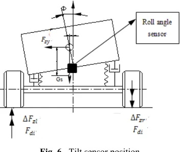
1.1 Sensor position determination
The heavy duty vehicle with non-independent balance suspension, the camber of the car body and the leaf spring of the balance suspension also appear lateral devia-tion when the vehicle rolls, and frame offset. The force diagram of the heavy vehicle is shown in Fig. 6.
Fig. 6. Tilt sensor position
6
Information processing unit modify ECU and information
output device
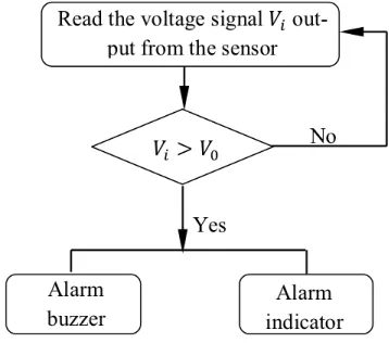
The voltage data from the voltage angle sensor is sent to the information pro-cessing unit ECU (Electronic Control Unit) through the data transmission system. Through modify ECU program [5] [6] that is to modified algorithm and store them in containers. The signal from the input device by the controller and converted to the signal processing to generate the corresponding instruction, and transferred out by the output transmission equipment. The modified part of the ECU program flow chart is shown in Fig 7.
Fig. 7. Flow chart of refitted part of ECU program
The information output equipment mainly includes the alarm buzzer and the warn-ing indicator light. ECU determines whether the value is greater than!! when the
output voltage of the tilt sensor is transmitted to the ECU by the data line. According to the different load of the car ahead of time to determine the car tilt limit angle [v],
!! is the maximum value of the permitted dip angle, it can be set to !!!=0.5[V]
be-cause it takes a certain amount of time to get the alarm for the driver. When the value read is greater than!!, ECU sends out control instructions and transmits instructions
to alarm buzzer and alarm light, or so ECU continue reading voltage values.
7
Conclusion
speed in order to minimize the possibility of rollover and reduce the probability of reaching an accident. The roll stability early warning system is of great significance to reduce the rollover accident probability of heavy haul vehicles, but further experi-mental analysis is needed.
8
References
[1]A Sathyanarayana , P Boyraz , JHL Hansen. Information fusion for robust ‘context and driver aware active vehicle safety systems. Information Fusion, 2011, 12 (4):293-303. https://doi.org/10.1016/j.inffus.2010.06.004
[2]LI Xu, H ERIC TSENG. Robust Model-Based Fault Detection for a Roll Stability Control System. IEEE Trans Control Systems Technology, 2007, 15(3): 519-528. https://doi.org/10.1109/TCST.2006.890287
[3]J Lu, D Filev, L Johnson. Real-time Tire Imbalance Detection Using ABS Wheel Speed Sensors, Sae International Journal of Materials & Manufacturing 2011, 4 (1):1036-1047. https://doi.org/10.4271/2011-01-0981
[4]W Kim, K Yi,J Lee. An optimal traction, braking, and steering coordination strategy for stability and manoeuvrability of a six-wheel drive and six-wheel steer vehicle. Proceedings of the Institution of Mechanical Engineers Part D Journal of Automobile Engineering, 2012,226 (1):3-22. https://doi.org/10.1177/0954407011416055
[5]Ernesto Gutiérrez González,Jesús Alvarez Flórez,Sebastién Arab. Development of the management strategies of the ECU for an internal combustion engine. Mechanical Systems and Signal Processing. 2008, Vol.22 (6), pp.1356-1373. https://doi.org/10.1016/j.ymssp.20 07.11.030
[6]XJ Fang , JY Du , MQ Jia , YN Yuan , X Wu. Development of ECU calibration system for electronic controlled engine based on LabVIEW. International Conference on Electric In-formation & Control Engineering. 2011:4930-4933. https://doi.org/10.1109/ICEICE.20 11.5776866
9
Author
Jingmei Zhang is with the School of Mechanical, Electric and Control Engineer-ing, Beijing Jiaotong University, BeijEngineer-ing, China and the School of Mechanical Engi-neering, Hebei University of Science and Technology, Shijiazhuang, China (e-mail: [email protected]).