Adv. Radio Sci., 10, 175–181, 2012 www.adv-radio-sci.net/10/175/2012/ doi:10.5194/ars-10-175-2012
© Author(s) 2012. CC Attribution 3.0 License.
Advances in
Radio Science
Design space exploration of high throughput finite field multipliers
for channel coding on Xilinx FPGAs
C. de Schryver, S. Weithoffer, U. Wasenm ¨uller, and N. Wehn
Microelectronic Systems Design Research Group, University of Kaiserslautern, Erwin-Schr¨odinger-Str., Germany Correspondence to: C. de Schryver ([email protected])
Abstract. Channel coding is a standard technique in all
wire-less communication systems. In addition to the typically em-ployed methods like convolutional coding, turbo coding or low density parity check (LDPC) coding, algebraic codes are used in many cases. For example, outer BCH coding is applied in the DVB-S2 standard for satellite TV broad-casting. A key operation for BCH and the related Reed-Solomon codes are multiplications in finite fields (Galois Fields), where extension fields of prime fields are used. A lot of architectures for multiplications in finite fields have been published over the last decades. This paper examines four different multiplier architectures in detail that offer the po-tential for very high throughputs. We investigate the imple-mentation performance of these multipliers on FPGA tech-nology in the context of channel coding. We study the effi-ciency of the multipliers with respect to area, frequency and throughput, as well as configurability and scalability. The implementation data of the fully verified circuits are provided for a Xilinx Virtex-4 device after place and route.
1 Introduction
Galois or finite field multiplications (FFMs) are key in a wide range of technical applications, for example in cryptography or channel coding. In particular BCH- and Reed-Solomon codes require a lot of Galois field (GF) multiplications to be performed in the decoding process. Nowadays, BCH codes are widely spread and employed in modern communication standards like DVB and in error correction units for flash memory devices (Liu et al., 2006), for instance. In Sect. 2 we summarize the theoretical background of FFM and BCH decoding.
However, the specific FFM requirements vary over the ap-plication range: high Galois field dimensions are used in cryptography, whereas for FFMs in channel coding the fo-cus lies on high throughput and low latency. FFMs are key
components in BCH decoder implementations and consume a significant amount of hardware resources in the overall de-sign (Chen et al., 2009; Zhang et al., 2010).
Up to now, a lot of research has been made on area effi-cient and fast FFM architectures. However, Ahlquist et al. haven shown in 1999 (Ahlquist et al., 1999) that not every VLSI optimized multiplier architecture performs optimal on FPGAs.
Already in 1986, Scott et al. have proposed a scalable FFM that is easily adaptable to different GF sizes and primi-tive polynomials (Scott et al., 1986). Their bit-slice architec-ture makes efficient use of area providing flexibility for dif-ferent field sizes. Building on the work of Scott et al., Kitsos et al. in 2003 proposed a flexible, reconfigurable FFM ar-chitecture for extension fieldsGF (2m)(Kitsos et al., 2003). Their bit-serial polynomial basis multiplier features reconfig-urability for field sizes up tomand reduced power consump-tion due to gated clocking. The low hardware complexity promises good area performance.
In this work, we investigate the potential benefit of these published FFM architectures as well as two “standard” ar-chitectures for a high-throughput DVB-S2 standard BCH de-coder. For this purpose we have implemented the selected FFMs as described in Sect. 3 and fully validated them with a hardware-software co-simulation setup. We have synthe-sized our implementations and compare area consumption and achievable throughput for a common Xilinx Virtex-4 FGPA target device as described in Sect. 4. Furthermore, we evaluate them with respect to their suitability for FPGA target devices, area consumption, latency and scalability. Finally, we comment on the impact of using sophisticated pipelined FFMs in a DVB-S2 BCH decoder and show which parts can profit most from those.
176 C. de Schryver et al.: Design space exploration of FFMs for channel coding 2 Theoretical background
For a better understanding of the finite field multiplier archi-tectures and the context of BCH coding, we give an overview on the underlying mathematics in this section. For more de-tails we refer to available standard literature (Bossert, 1998; Friedrichs, 1995).
2.1 Finite fields and multiplication
The basis for the finite field multiplication architectures im-plemented in this work is a reformulation of the finite field multiplication in polynomial representation. The derivation of the algorithm originally proposed by Scott et al. (Scott et al., 1986) is outlined in the following.
The nonzero elements of the extension fieldGF (2m)can be constructed by powers of the primitive elementα, whereα
is a root of a primitive polynomialP (x)=xm+pm−1xm−1+ ··· +p1x+p0overGF (2). SinceP (α)=0 (αbeing root of
P)αm=pm−1αm−1+ ··· +p1α+p0and therefore nonzero the elements can be written in the canonical base representa-tion:
{am−1αm−1+ ··· +a1α+a0|ai∈GF (2)for 0≤i≤m−1}
2.1.1 Multiplication algorithm
Based on the work of Scott et al., an algorithm for FFM can be derived similar to the design proposed by Kitsos et al. as follows: LetA,B∈GF (2m)in canonical base representa-tion andP primitive polynomial overGF (2). Then let
C=A(x)·B(x)modP (1)
= m−1
X k=0
A(x)·bkxkmodP (2)
=((0·x+bm−1A(x))
| {z }
K0(x)
xm−1+ ··· +b0A(x))modP (x) (3)
=(K0(x)x+bm−2A(x)
| {z }
K1(x)
xm−2+ ··· +b0A(x))modP (x) (4)
.. .
=Km−1(x)modP (x) (5)
Thus, the productC(x)can be obtained by performing it-erativelym−1 times:
Ki(x)=
Ki−1(x)x+bm−1−iA(x)
modP (x) (6) whereK−1(x)=0.
2 C. de Schryver, S. Weithoffer, U. Wasenm¨uller, N. Wehn: Design Space Exploration of FFMs for Channel Coding
2 Theoretical Background
For a better understanding of the finite field multiplier archi-tectures and the context of BCH coding, we give an overview on the underlying mathematics in this section. For more de-tails we refer to available standard literature (Bossert, 1998) (Friedrichs, 1995).
2.1 Finite Fields and Multiplication
The basis for the finite field multiplication architectures im-plemented in this work is a reformulation of the finite field multiplication in polynomial representation. The derivation of the algorithm originally proposed by Scott et al. (Scott et al., 1986) is outlined in the following.
The nonzero elements of the extension field GF(2m)
can be constructed by powers of the primitive element α, where α is a root of a primitive polynomialP(x) =xm+
pm−1x
m−1+···+p
1x+p0 over GF(2). Since P(α) = 0
(α being root ofP)αm=p m−1α
m−1+···+p
1α+p0and
therefore nonzero the elements can be written in the canoni-cal base representation:
{am−1α
m−1+···+a
1α+a0|ai∈GF(2)for0≤i≤m−1}
2.1.1 Multiplication Algorithm
Based on the work of Scott et al., an algorithm for FFM can be derived similar to the design proposed by Kitsos et al. as follows: LetA,B∈GF(2m)in canonical base
representa-tion andP primitive polynomial overGF(2). Then let
C=A(x)·B(x) modP (1)
=
m−1 X
k=0
A(x)·bkxk modP (2)
= ((0·x+bm−1A(x))
| {z }
K0 (x)
xm−1+···+b
0A(x)) modP(x) (3)
= (!K0(x)x+bm−2A(x)
| {z }
K1(x)
xm−2+···+b
0A(x)) modP(x)(4)
.. .
=Km−1(x) modP(x) (5)
Thus, the productC(x)can be obtained by performing it-erativelym−1times:
Ki(x) =!Ki−1(x)x+b
m−1−iA(x)
modP(x) (6)
whereK−1(x) = 0.
Equation (6) can be simplified by using the fact that
xmmodP(x) =p m−1x
m−1+···+p
1x+p0 and by
writ-ing Ki−1(x) and A(x) as ki−1
m−1x
m−1+···+ki−1
0 and am−1x
m−1+···+a
0respectively and one obtains:
Ki(x) =
m−1 X
j=0 kijx
j
(7)
with
ki j=k
i−1
m−1pj+k
i−1
j−1+bm−1−iaj and k
i−1
−1 = 0 (8) With (6) and (8), the multiplication algorithm over
GF(2m)is given, that is used for the architectures of the
Scott- and Kitsos-multiplier.
2.2 BCH Decoding
BCH codes have been invented in 1959 by Hocquenghem (Hocquenghem, 1959), and independently in 1960 by Bose and Ray-Chaudhuri (Bose and Ray-Chaudhuri, 1960). These codes provide high flexibility and predictable error correc-tion ability, and hence are used in a wide range of technical applications. Details about their construction and decoding can be found in literature (Bossert, 1998) (Friedrichs, 1995). Two main categories of BCH codes exist: so-called prim-itiveandnon-primitiveones. Code words of primitive BCH codes are always of fixed lengthn= 2m−1, withnbeing
the length of the code word andmthe dimension of the Ga-lois field2m. Non-primitive BCH codes provide flexibility
in choosing the appropriate code word size. In contrast to code puncturing, where one or more positions in a code word are omitted, the minimum distance in a reduced code is not changed (Bossert, 1998). Non-primitive BCH codes are used in standards like DVB-T2, DVB-S2, DB-C2, DVB-H, ITU-T H.261 or ITU-T G.975.1, for example.
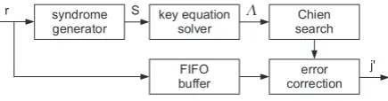
BCH codes are usually decoded by algebraic syndrome de-coding. Figure 1 shows the generic structure of a syndrome based BCH decoder.
syndrome generator
key equation solver
Chien search FIFO
buffer
error correction
r S
j'
(
Fig. 1: Block Diagram of an BCH Decoder
It is important to notice that the syndromeS(x)only de-pends on a possible error vectoreand not on the correct code word that has been sent. The decoder therefore has to find a possible error vectorewith a minimum weight, that means anewith a minimum number of coefficients unequal to zero. In order to calculateealgebraically, the search for minimum weight is transformed into a search for a polynomial with minimum degree (Bossert, 1998).
Fig. 1. Block Diagram of an BCH Decoder.
Equation (6) can be simplified by using the fact that
xmmodP (x)=pm−1xm−1+ ··· +p1x+p0 and by writ-ing Ki−1(x) and A(x) as km−i−11xm−1+ ··· +ki−0 1 and
am−1xm−1+ ··· +a0respectively and one obtains:
Ki(x)= m−1 X j=0
kjixj (7)
with
kij=km−i−11pj+kji−−11+bm−1−iaj and k−i−11=0 (8) With Eqs. (6) and (8), the multiplication algorithm over
GF (2m) is given, that is used for the architectures of the Scott- and Kitsos-multiplier.
2.2 BCH decoding
BCH codes have been invented in 1959 by Hoc-quenghem (HocHoc-quenghem, 1959), and independently in 1960 by Bose and Ray-Chaudhuri (Bose and Ray-Chaudhuri, 1960). These codes provide high flexibility and predictable error correction ability, and hence are used in a wide range of technical applications. Details about their construction and decoding can be found in literature (Bossert, 1998; Friedrichs, 1995).
Two main categories of BCH codes exist: so-called prim-itive and non-primprim-itive ones. Code words of primprim-itive BCH codes are always of fixed length n=2m−1, withn being the length of the code word andmthe dimension of the Ga-lois field 2m. Non-primitive BCH codes provide flexibility in choosing the appropriate code word size. In contrast to code puncturing, where one or more positions in a code word are omitted, the minimum distance in a reduced code is not changed (Bossert, 1998). Non-primitive BCH codes are used in standards like DVB-T2, DVB-S2, DB-C2, DVB-H, ITU-T H.261 or ITU-T G.975.1, for example.
BCH codes are usually decoded by algebraic syndrome de-coding. Figure 1 shows the generic structure of a syndrome based BCH decoder.
It is important to notice that the syndromeS(x)only de-pends on a possible error vectoreand not on the correct code word that has been sent. The decoder therefore has to find a possible error vectorewith a minimum weight, that means anewith a minimum number of coefficients unequal to zero. In order to calculateealgebraically, the search for minimum
C. de Schryver et al.: Design space exploration of FFMs for channel coding 177
weight is transformed into a search for a polynomial with minimum degree (Bossert, 1998).
The syndrome generator unit (SGU) computes the syn-dromeS(x) that is fed into a so-called key equation solver (KES). The KES computes the error locator polynomial
3(x)out of the syndrome. The Chien search unit (CSU) af-terwards checks for all elements in the specified Galois field
GF (2m)if3(x)=0. In this case, the error vectorehas a 1 at the corresponding position; the error correction then flips the bits at all recognized error positions in the received code wordr.
3 Hardware implementation
The hardware implementation of the FFMs should be flexi-ble and generic with respect to the primitive polynomial and field size. Furthermore, they should exploit the underlying structures of the Virtex-4 FPGA-platform well to yield small area usage while providing sufficient throughput.
For the target DVB-S2 standard, BCH codes based on the Galois fields 214and 216are used. As this research was per-formed in the context of a more complex communication sys-tem, the common clock frequency of the whole system was predefined to 200MHz.
The hardware implementations considered in our work are based on (Scott et al., 1986) and (Kitsos et al., 2003). Fur-thermore, we give insight into the architecture of the plain combinatorial FFM implementations used.
3.1 Scott-Multiplier
The architecture of the Scott-multiplier resembles the mul-tiplication algorithm derived in Sect. 2.1. Equation (8) is mapped to a basic cell (see Fig. 2). It consists of two 2-input AND-gates, two 2-input XOR gates and a flip-flop. Addi-tionally, our implementation contains flip-flops for storing the coefficients of the A-operand during a calculation and control logic for that. Still, such cells fit comfortably into a Virtex-4 FPGA slice that offers two 4-input LUTs, two mul-tiplexers, two 1-bit registers and arithmetic logic.
For a multiplier overGF (2m),mbasic cells are connected into an array that calculates the productC=A·BmodP in
mclock cycles. This array can be viewed as a linear feed-back shift register and is illustrated in Fig. 3. The primitive polynomial of the Galois field can arbitrarily be set at design time.
3.2 Kitsos-multiplier
This architecture extends the Scott-multiplier by a reconfig-urable feedback path, gated clocking and is also based on Eq. (8). The reconfigurable feedback path allows for a run-time reconfiguration of the multiplier. This reconfigurabil-ity aims to support not only arbitrary primitive polynomials but also field sizes 1≤i≤mfor an array length m. The
C. de Schryver, S. Weithoffer, U. Wasenm¨uller, N. Wehn: Design Space Exploration of FFMs for Channel Coding
3
The syndrome generator unit (SGU) computes the
syn-drome
S
(
x
)
that is fed into a so-called
key equation solver
(KES). The KES computes the
error locator polynomial
Λ(
x
)
out of the syndrome. The Chien search unit (CSU)
af-terwards checks for all elements in the specified Galois field
GF
(2
m)
if
Λ(
x
) = 0
. In this case, the error vector
e
has a
1
at the corresponding position; the error correction then flips
the bits at all recognized error positions in the received code
word
r
.
3
Hardware Implementation
The hardware implementation of the FFMs should be
flexi-ble and generic with respect to the primitive polynomial and
field size. Furthermore, they should exploit the underlying
structures of the Virtex-4 FPGA-platform well to yield small
area usage while providing sufficient throughput.
For the target DVB-S2 standard, BCH codes based on the
Galois fields
2
14and
2
16are used. As this research was
per-formed in the context of a more complex communication
sys-tem, the common clock frequency of the whole system was
predefined to 200MHz.
The hardware implementations considered in our work are
based on (Scott et al., 1986) and (Kitsos et al., 2003).
Fur-thermore, we give insight into the architecture of the plain
combinatorial FFM implementations used.
3.1
Scott-Multiplier
The architecture of the Scott-multiplier resembles the
mul-tiplication algorithm derived in Section 2.1. Equation (8)
is mapped to a basic cell (see Figure 2). It consists of two
2-input AND-gates, two 2-input XOR gates and a flip-flop.
Additionally, our implementation contains flip-flops for
stor-ing the coefficients of the
A
-operand during a calculation and
control logic for that. Still, such cells fit comfortably into a
Virtex-4 FPGA slice that offers two 4-input LUTs, two
mul-tiplexers, two 1-bit registers and arithmetic logic.
For a multiplier over
GF
(2
m)
,
m
basic cells are connected
into an array that calculates the product
C
=
A
·
B
mod
P
in
m
clock cycles. This array can be viewed as a linear
feed-back shift register and is illustrated in Figure 3. The primitive
polynomial of the Galois field can arbitrarily be set at design
time.
3.2
Kitsos-Multiplier
This architecture extends the Scott-multiplier by a
reconfig-urable feedback path, gated clocking and is also based on
Equation (8). The reconfigurable feedback path allows for a
run-time reconfiguration of the multiplier. This
reconfigura-bility aims to support not only arbitrary primitive
polynomi-als but polynomi-also field sizes
1
≤
i
≤
m
for an array length
m
. The
gated clocking leads to an increased power efficiency when
the multiplier is reconfigured to lower dimension fields.
Fig. 2: Scott-Multiplier Basic Cell
Fig. 3: Scott-Multiplier Array of Four Cells for
m
= 4
.
In addition to the two 2-input AND-gates, two 2-input
XOR gates and flip-flop required due to Equation (8), the
basic cells of the Kitsos-multiplier contain a demultiplexer
and a two-input XOR and AND gate as shown in Figure 4.
Similar to the Scott-multiplier,
m
basic cells form an
ar-ray to allow for multiplication over
GF
(2
m)
. The
Kitsos-multiplier can be reconfigured at run time to support any field
dimension
j
with
1
≤
j
≤
m
by selecting a shorter feedback
path and disabling part of the flip-flops. Our
implementa-tion also features built-in default primitive polynomials and
further control logic to be able to use an arbitrary primitive
polynomial. An example for
m
= 4
is given in Figure 5.
3.3
Plain Multiplier Architectures
In the original BCH decoder implementation, the multipliers
used were based on a pure polynomial division algorithm.
As a first step, plain unrolling of this polynomial division
led to pure combinatorial FFMs. In the second step we have
introduced pipeline registers to shorten the critical path of the
circuit.
We use both plain FFM types as a comparison for our
re-sults. Detailed numbers for all multipliers are given in
Fig-ure 8 and Table 2.
Fig. 2. Scott-Multiplier Basic Cell.
C. de Schryver, S. Weithoffer, U. Wasenm¨uller, N. Wehn: Design Space Exploration of FFMs for Channel Coding 3
The syndrome generator unit (SGU) computes the syn-dromeS(x)that is fed into a so-calledkey equation solver
(KES). The KES computes the error locator polynomial Λ(x)out of the syndrome. The Chien search unit (CSU) af-terwards checks for all elements in the specified Galois field
GF(2m)ifΛ(x) = 0. In this case, the error vectorehas a1
at the corresponding position; the error correction then flips the bits at all recognized error positions in the received code wordr.
3 Hardware Implementation
The hardware implementation of the FFMs should be flexi-ble and generic with respect to the primitive polynomial and field size. Furthermore, they should exploit the underlying structures of the Virtex-4 FPGA-platform well to yield small area usage while providing sufficient throughput.
For the target DVB-S2 standard, BCH codes based on the Galois fields214and216are used. As this research was
per-formed in the context of a more complex communication sys-tem, the common clock frequency of the whole system was predefined to 200MHz.
The hardware implementations considered in our work are based on (Scott et al., 1986) and (Kitsos et al., 2003). Fur-thermore, we give insight into the architecture of the plain combinatorial FFM implementations used.
3.1 Scott-Multiplier
The architecture of the Scott-multiplier resembles the mul-tiplication algorithm derived in Section 2.1. Equation (8) is mapped to a basic cell (see Figure 2). It consists of two 2-input AND-gates, two 2-input XOR gates and a flip-flop. Additionally, our implementation contains flip-flops for stor-ing the coefficients of theA-operand during a calculation and control logic for that. Still, such cells fit comfortably into a Virtex-4 FPGA slice that offers two 4-input LUTs, two mul-tiplexers, two 1-bit registers and arithmetic logic.
For a multiplier overGF(2m),mbasic cells are connected
into an array that calculates the productC=A·BmodP in
mclock cycles. This array can be viewed as a linear feed-back shift register and is illustrated in Figure 3. The primitive polynomial of the Galois field can arbitrarily be set at design time.
3.2 Kitsos-Multiplier
This architecture extends the Scott-multiplier by a reconfig-urable feedback path, gated clocking and is also based on Equation (8). The reconfigurable feedback path allows for a run-time reconfiguration of the multiplier. This reconfigura-bility aims to support not only arbitrary primitive polynomi-als but polynomi-also field sizes1≤i≤mfor an array lengthm. The gated clocking leads to an increased power efficiency when the multiplier is reconfigured to lower dimension fields.
Fig. 2: Scott-Multiplier Basic Cell
Fig. 3: Scott-Multiplier Array of Four Cells form= 4.
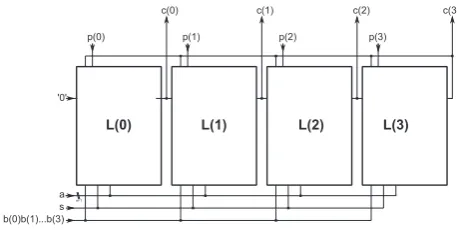
In addition to the two 2-input AND-gates, two 2-input XOR gates and flip-flop required due to Equation (8), the basic cells of the Kitsos-multiplier contain a demultiplexer and a two-input XOR and AND gate as shown in Figure 4.
Similar to the Scott-multiplier,mbasic cells form an ar-ray to allow for multiplication overGF(2m). The
Kitsos-multiplier can be reconfigured at run time to support any field dimensionjwith1≤j≤mby selecting a shorter feedback path and disabling part of the flip-flops. Our implementa-tion also features built-in default primitive polynomials and further control logic to be able to use an arbitrary primitive polynomial. An example form= 4is given in Figure 5.
3.3 Plain Multiplier Architectures
In the original BCH decoder implementation, the multipliers used were based on a pure polynomial division algorithm. As a first step, plain unrolling of this polynomial division led to pure combinatorial FFMs. In the second step we have introduced pipeline registers to shorten the critical path of the circuit.
We use both plain FFM types as a comparison for our re-sults. Detailed numbers for all multipliers are given in Fig-ure 8 and Table 2.
Fig. 3. Scott-Multiplier Array of Four Cells form=4.
gated clocking leads to an increased power efficiency when the multiplier is reconfigured to lower dimension fields.
In addition to the two 2-input AND-gates, two 2-input XOR gates and flip-flop required due to Eq. (8), the basic cells of the Kitsos-multiplier contain a demultiplexer and a two-input XOR and AND gate as shown in Fig. 4.
Similar to the Scott-multiplier,mbasic cells form an ar-ray to allow for multiplication over GF (2m). The Kitsos-multiplier can be reconfigured at run time to support any field dimensionj with 1≤j≤mby selecting a shorter feedback path and disabling part of the flip-flops. Our implementa-tion also features built-in default primitive polynomials and further control logic to be able to use an arbitrary primitive polynomial. An example form=4 is given in Fig. 5.
3.3 Plain multiplier architectures
In the original BCH decoder implementation, the multipliers used were based on a pure polynomial division algorithm. As a first step, plain unrolling of this polynomial division led to pure combinatorial FFMs. In the second step we have
178 C. de Schryver et al.: Design space exploration of FFMs for channel coding
4
C. de Schryver, S. Weithoffer, U. Wasenm¨uller, N. Wehn: Design Space Exploration of FFMs for Channel Coding
Fig. 4: Kitsos-Multiplier Basic Cell
Fig. 5: Kitsos-Multiplier Array for Maximum
m
= 4
3.4
BCH Decoder Architecture
Our original decoder implementation is derived from the
generic template shown in Figure 1. The key equation solver
is based on a fully parallel Euclidean implementation that
uses non-pipelined combinatorial FFMs as described in
Sec-tion 3.3. SGU and CSU use the same type of FFM. Since we
intend to enhance our decoder to Reed-Solomon codes in the
future, we have decided to go for a fully parallel Euclidean
based key equation solver. The decoder can be configured at
design time with the following parameters:
–
n
: length of the code word
–
m
: dimension of the extension field
2
m–
t
: numbers of errors that can be corrected
–
p
: number of bits that are processed in parallel in the
syndrome generator unit and the Chien search unit
In all three units in the upper part of Figure 1, FFMs are
the key components (Chen et al., 2009) (Zhang et al., 2010).
However, the complexity of some FFMs can be reduced at
design time, since they have one input fixed to a constant
value out of the specific Galois field used. This is the case
for all
2
∗
t
multipliers in the syndrome computation unit and
for all
t
∗
p
multipliers in the Chien search unit.
The key equation solver only contains full FFMs with
non-constant inputs. To support both GF dimensions (
2
14and
2
16) in the DVB-S2 BCH decoder, every FFM instance
in-ternally consists of two FFMs, one for each GF dimension.
!
"#$ %"$ &'" (
inner: m=8, n=128, t=3, p=1 / outer: m=13, n=4096, t=7, p=1
Fig. 6: Slice Distribution of BCH Decoder Components
They share the same wires and are selected via multiplexers
at the inputs and outputs.
Figure 6 clearly shows for two explicit configuration cases
that these
8
∗
t
+ 2
FFMs in total consume the vast majority
of the overall area required by the complete BCH decoder.
In Table 1 the latency of the single decoder stages is given
for combinatorial and Scott FFMs based on the decoder
pa-rameters. Due to the high parallelism in the KES, the
major-ity of decoding time is spend in SGU and CSU. Nevertheless,
these units can easily be speeded up by increasing
p
,
reduc-ing the latency in these units by
1
/p
. However, this will also
increase the consumed area by a factor of nearly
p
.
4
Results
4.1
Validation
With increasing complexity in current hardware designs,
per-manent evaluation and verification is crucial throughout the
design process. To speed up the otherwise very time
consum-ing simulation process, the VHDL models of the FFMs have
been exhaustively co-simulated with C++ reference code for
GF-multiplication. This co-simulation has been carried out
using Mentor Graphics ModelSim and a SystemC test bench
as illustrated in Figure 7. As only field sizes up to
2
16are
of interest for our BCH decoder, all meaningful stimuli have
been applied and the models have therefore been fully
veri-fied.
4.2
Synthesis Results
All multiplier architectures described in Section 3 have been
implemented in VDHL. They have been synthesized for low
area consumption on a Xilinx Virtex 4 FPGA (XC4VLX100,
package FF1148). The applied tool chain was Xilinx ISE
IDE Release 11.3 and the optimization effort for place and
route was set to high. Table 2 gives detailed synthesis results
(post place and route).
Fig. 4. Kitsos-Multiplier Basic Cell.
4 C. de Schryver, S. Weithoffer, U. Wasenm¨uller, N. Wehn: Design Space Exploration of FFMs for Channel Coding
Fig. 4: Kitsos-Multiplier Basic Cell
Fig. 5: Kitsos-Multiplier Array for Maximumm= 4
3.4 BCH Decoder Architecture
Our original decoder implementation is derived from the generic template shown in Figure 1. The key equation solver is based on a fully parallel Euclidean implementation that uses non-pipelined combinatorial FFMs as described in Sec-tion 3.3. SGU and CSU use the same type of FFM. Since we intend to enhance our decoder to Reed-Solomon codes in the future, we have decided to go for a fully parallel Euclidean based key equation solver. The decoder can be configured at design time with the following parameters:
– n: length of the code word
– m: dimension of the extension field2m
– t: numbers of errors that can be corrected
– p: number of bits that are processed in parallel in the syndrome generator unit and the Chien search unit
In all three units in the upper part of Figure 1, FFMs are the key components (Chen et al., 2009) (Zhang et al., 2010). However, the complexity of some FFMs can be reduced at design time, since they have one input fixed to a constant value out of the specific Galois field used. This is the case for all2∗tmultipliers in the syndrome computation unit and for allt∗pmultipliers in the Chien search unit.
The key equation solver only contains full FFMs with non-constant inputs. To support both GF dimensions (214 and 216) in the DVB-S2 BCH decoder, every FFM instance
in-ternally consists of two FFMs, one for each GF dimension.
!
"#$ %"$ &'" (
inner: m=8, n=128, t=3, p=1 / outer: m=13, n=4096, t=7, p=1
Fig. 6: Slice Distribution of BCH Decoder Components
They share the same wires and are selected via multiplexers at the inputs and outputs.
Figure 6 clearly shows for two explicit configuration cases that these8∗t+ 2FFMs in total consume the vast majority of the overall area required by the complete BCH decoder.
In Table 1 the latency of the single decoder stages is given for combinatorial and Scott FFMs based on the decoder pa-rameters. Due to the high parallelism in the KES, the major-ity of decoding time is spend in SGU and CSU. Nevertheless, these units can easily be speeded up by increasingp, reduc-ing the latency in these units by1/p. However, this will also increase the consumed area by a factor of nearlyp.
4 Results
4.1 Validation
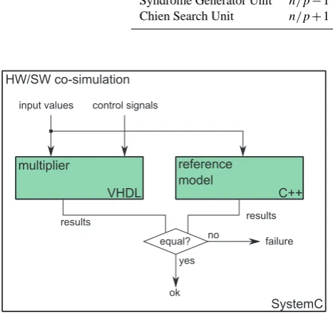
With increasing complexity in current hardware designs, per-manent evaluation and verification is crucial throughout the design process. To speed up the otherwise very time consum-ing simulation process, the VHDL models of the FFMs have been exhaustively co-simulated with C++ reference code for GF-multiplication. This co-simulation has been carried out using Mentor Graphics ModelSim and a SystemC test bench as illustrated in Figure 7. As only field sizes up to216are
of interest for our BCH decoder, all meaningful stimuli have been applied and the models have therefore been fully veri-fied.
4.2 Synthesis Results
All multiplier architectures described in Section 3 have been implemented in VDHL. They have been synthesized for low area consumption on a Xilinx Virtex 4 FPGA (XC4VLX100, package FF1148). The applied tool chain was Xilinx ISE IDE Release 11.3 and the optimization effort for place and route was set to high. Table 2 gives detailed synthesis results (post place and route).
Fig. 5. Kitsos-Multiplier Array for Maximumm=4.
introduced pipeline registers to shorten the critical path of the circuit.
We use both plain FFM types as a comparison for our re-sults. Detailed numbers for all multipliers are given in Fig. 2 and Table 2.
3.4 BCH decoder architecture
Our original decoder implementation is derived from the generic template shown in 1. The key equation solver is based on a fully parallel Euclidean implementation that uses non-pipelined combinatorial FFMs as described in Sect. 3.3. SGU and CSU use the same type of FFM. Since we intend to enhance our decoder to Reed-Solomon codes in the future, we have decided to go for a fully parallel Euclidean based key equation solver. The decoder can be configured at de-sign time with the following parameters:
– n: length of the code word
– m: dimension of the extension field 2m
– t: numbers of errors that can be corrected
– p: number of bits that are processed in parallel in the syndrome generator unit and the Chien search unit In all three units in the upper part of Fig. 1, FFMs are the key components (Chen et al., 2009; Zhang et al., 2010).
4 C. de Schryver, S. Weithoffer, U. Wasenm¨uller, N. Wehn: Design Space Exploration of FFMs for Channel Coding
Fig. 4: Kitsos-Multiplier Basic Cell
Fig. 5: Kitsos-Multiplier Array for Maximumm= 4
3.4 BCH Decoder Architecture
Our original decoder implementation is derived from the generic template shown in Figure 1. The key equation solver is based on a fully parallel Euclidean implementation that uses non-pipelined combinatorial FFMs as described in Sec-tion 3.3. SGU and CSU use the same type of FFM. Since we intend to enhance our decoder to Reed-Solomon codes in the future, we have decided to go for a fully parallel Euclidean based key equation solver. The decoder can be configured at design time with the following parameters:
– n: length of the code word
– m: dimension of the extension field2m
– t: numbers of errors that can be corrected
– p: number of bits that are processed in parallel in the syndrome generator unit and the Chien search unit
In all three units in the upper part of Figure 1, FFMs are the key components (Chen et al., 2009) (Zhang et al., 2010). However, the complexity of some FFMs can be reduced at design time, since they have one input fixed to a constant value out of the specific Galois field used. This is the case for all2∗tmultipliers in the syndrome computation unit and for allt∗pmultipliers in the Chien search unit.
The key equation solver only contains full FFMs with non-constant inputs. To support both GF dimensions (214 and
216) in the DVB-S2 BCH decoder, every FFM instance
in-ternally consists of two FFMs, one for each GF dimension.
!
"#$ %"$ &'" (
inner: m=8, n=128, t=3, p=1 / outer: m=13, n=4096, t=7, p=1
Fig. 6: Slice Distribution of BCH Decoder Components
They share the same wires and are selected via multiplexers at the inputs and outputs.
Figure 6 clearly shows for two explicit configuration cases that these8∗t+ 2FFMs in total consume the vast majority of the overall area required by the complete BCH decoder.
In Table 1 the latency of the single decoder stages is given for combinatorial and Scott FFMs based on the decoder pa-rameters. Due to the high parallelism in the KES, the major-ity of decoding time is spend in SGU and CSU. Nevertheless, these units can easily be speeded up by increasingp, reduc-ing the latency in these units by1/p. However, this will also increase the consumed area by a factor of nearlyp.
4 Results
4.1 Validation
With increasing complexity in current hardware designs, per-manent evaluation and verification is crucial throughout the design process. To speed up the otherwise very time consum-ing simulation process, the VHDL models of the FFMs have been exhaustively co-simulated with C++ reference code for GF-multiplication. This co-simulation has been carried out using Mentor Graphics ModelSim and a SystemC test bench as illustrated in Figure 7. As only field sizes up to 216 are
of interest for our BCH decoder, all meaningful stimuli have been applied and the models have therefore been fully veri-fied.
4.2 Synthesis Results
All multiplier architectures described in Section 3 have been implemented in VDHL. They have been synthesized for low area consumption on a Xilinx Virtex 4 FPGA (XC4VLX100, package FF1148). The applied tool chain was Xilinx ISE IDE Release 11.3 and the optimization effort for place and route was set to high. Table 2 gives detailed synthesis results (post place and route).
Fig. 6. Slice Distribution of BCH Decoder Components.
However, the complexity of some FFMs can be reduced at design time, since they have one input fixed to a constant value out of the specific Galois field used. This is the case for all 2×tmultipliers in the syndrome computation unit and for allt×pmultipliers in the Chien search unit.
The key equation solver only contains full FFMs with non-constant inputs. To support both GF dimensions (214 and 216) in the DVB-S2 BCH decoder, every FFM instance in-ternally consists of two FFMs, one for each GF dimension. They share the same wires and are selected via multiplexers at the inputs and outputs.
Figure 6 clearly shows for two explicit configuration cases that these 8×t+2 FFMs in total consume the vast majority of the overall area required by the complete BCH decoder.
InTable 1 the latency of the single decoder stages is given for combinatorial and Scott FFMs based on the decoder pa-rameters. Due to the high parallelism in the KES, the major-ity of decoding time is spend in SGU and CSU. Nevertheless, these units can easily be speeded up by increasingp, reduc-ing the latency in these units by 1/p. However, this will also increase the consumed area by a factor of nearlyp.
4 Results 4.1 Validation
With increasing complexity in current hardware designs, per-manent evaluation and verification is crucial throughout the design process. To speed up the otherwise very time consum-ing simulation process, the VHDL models of the FFMs have been exhaustively co-simulated with C++ reference code for GF-multiplication. This co-simulation has been carried out using Mentor Graphics ModelSim and a SystemC test bench as illustrated in Fig. 7. As only field sizes up to 216are of in-terest for our BCH decoder, all meaningful stimuli have been applied and the models have therefore been fully verified.
C. de Schryver et al.: Design space exploration of FFMs for channel coding 179
Table 1. Latency Distribution of BCH Decoder Components.
Component Latency Combinatorial FFMs Latency Scott FFMs
Key Equation Solver 4×t+2 (4×t+2)×m
Syndrome Generator Unit n/p−1 (n/p−1)×m
Chien Search Unit n/p+1 (n/p+1)×m
C. de Schryver, S. Weithoffer, U. Wasenm¨uller, N. Wehn: Design Space Exploration of FFMs for Channel Coding
5
Component
Latency Combinatorial FFMs
Latency Scott FFMs
Key Equation Solver
4
∗
t
+ 2
(4
∗
t
+ 2)
∗
m
Syndrome Generator Unit
n/p
−
1
(
n/p
−
1)
∗
m
Chien Search Unit
n/p
+ 1
(
n/p
+ 1)
∗
m
Table 1: Latency Distribution of BCH Decoder Components
Fig. 7: HW/SW Co-Simulation Schematic
Fig. 8: Throughput per Slice @200MHz
Due to the given system requirements, the main focus lay
on a resulting small footprint on the FPGA for given
through-puts. Therefore the metric considered most important was
throughput per slice at a fixed clock frequency.
Table 2
shows that the required target clock frequency of 200MHz
could be achieved by all implementations, except the
Kitsos-multiplier for field dimensions
m
≥
15
.
For the Scott-multiplier, we can achieve possible clock
fre-quencies of more than
1GHz
due to the short critical path
(see Figure 2).
Furthermore, the Scott-multiplier
outper-forms the other multiplier architectures and even the plain
combinatorial multiplier implementation with respect to the
metric introduced above. This is shown in Figure 8.
When comparing the Scott-multiplier and the plain
com-binatorial multiplier, the area saving outweighs the lesser
throughput (factor
m1) by a factor from 14.75 (for
m
= 12
)
up to 18.1 (for
m
= 16
).
The overhead of the Kitsos-multiplier implementation
heavily impacts the area usage.
While still less area is
needed as for either one of the polynomial-division-based
multipliers, the Kitsos-multiplier requires roughly ten times
more area than the Scott-multiplier yet providing the same
throughput. A BCH decoder for DVB-S2 requires FFMs for
two different GF dimensions:
2
14and
2
16. As a result, two
instances of the Scott-multiplier (one for each dimension)
outperform the Kitsos-multiplier clearly.
4.3
Impact on BCH Decoder
With respect to the consumed area, Table 2 shows that the
the total number of slices occupied by the Scott-multiplier
is 9 for GF
2
14. That are 5.4% of the
168
slices required
by the plain combinatorial FFM for this GF dimension. For
GF
2
16, the Scott-FFM only consumes 5.5% of area. For
the FFM pairs in the DVB-S2 decoder as explained in
Sec-tion 3.4, this results in a total area saving of around 94% for
the FFMs. With respect to Figure 6, we thus expect a very
high potential for area saving by employing Scott-FFMs in
the key equation solver part. Nevertheless, the area occupied
by the multiplexers and registers will not be reduced.
Fur-thermore, the area reduction of FFMs with constant inputs as
in the SGU and CSU will also be significantly lower.
By using pipelined multipliers, the latency in each decoder
component is increased by a factor of
m
(see Table 1). For
the configurations shown in Figure 6, the latencies of SGU
and CSU are already massively dominating over the KES
la-tency. Using pipelined FFMs in SGU and CSU would there
lead to a significant decrease of the overall decoder
through-put, by only small area reduction in total.
However, Figure 6 shows that the KES is the dominating
part in the decoder with respect to area, but hardly contributes
to the overall latency. This means that adding additional
la-tency in the KES will only insignificantly increase the overall
latency of the decoder. On the other hand, smaller FFMs in
the KES will show a considerable impact on the overall
con-sumed area, since those FFMs use up most of the hardware
resources (see Section 3.4).
In order to achieve a well-balanced decoder design, we
therefore suggest to employ two different FFM types in the
decoder: combinatorial FFMs in the SGU and CSU, and
small pipelined FFMs in the KES. This setup will exploit
the benefits of both FFM types and reduce the overall area of
the decoder, by only adding an insignificant amount of total
latency.
Fig. 7. HW/SW Co-Simulation Schematic.
4.2 Synthesis results
All multiplier architectures described in 3 have been im-plemented in VDHL. They have been synthesized for low area consumption on a Xilinx Virtex 4 FPGA (XC4VLX100, package FF1148). The applied tool chain was Xilinx ISE IDE Release 11.3 and the optimization effort for place and route was set to high. Figure 2 gives detailed synthesis re-sults (post place and route).
Due to the given system requirements, the main focus lay on a resulting small footprint on the FPGA for given through-puts. Therefore the metric considered most important was throughput per slice at a fixed clock frequency. Figure 2 shows that the required target clock frequency of 200 MHz could be achieved by all implementations, except the Kitsos-multiplier for field dimensionsm≥15.
For the Scott-multiplier, we can achieve possible clock fre-quencies of more than 1 GHz due to the short critical path (see Fig. 2). Furthermore, the Scott-multiplier outperforms the other multiplier architectures and even the plain combi-natorial multiplier implementation with respect to the metric introduced above. This is shown in Fig. 2.
When comparing the Scott-multiplier and the plain com-binatorial multiplier, the area saving outweighs the lesser throughput (factor m1) by a factor from 14.75 (for m=12) up to 18.1 (form=16).
The overhead of the Kitsos-multiplier implementation
2 C. de Schryver, S. Weithoffer, U. Wasenm¨uller, N. Wehn: Design Space Exploration of FFMs for Channel Coding
2 Theoretical Background
For a better understanding of the finite field multiplier archi-tectures and the context of BCH coding, we give an overview on the underlying mathematics in this section. For more de-tails we refer to available standard literature (Bossert, 1998) (Friedrichs, 1995).
2.1 Finite Fields and Multiplication
The basis for the finite field multiplication architectures im-plemented in this work is a reformulation of the finite field multiplication in polynomial representation. The derivation of the algorithm originally proposed by Scott et al. (Scott et al., 1986) is outlined in the following.
The nonzero elements of the extension field GF(2m)
can be constructed by powers of the primitive element α, where α is a root of a primitive polynomialP(x) =xm+
pm−1x
m−1+···+p
1x+p0 over GF(2). Since P(α) = 0
(α being root ofP)αm=p m−1α
m−1+···+p
1α+p0and
therefore nonzero the elements can be written in the canoni-cal base representation:
{am−1α
m−1+···+a
1α+a0|ai∈GF(2)for0≤i≤m−1}
2.1.1 Multiplication Algorithm
Based on the work of Scott et al., an algorithm for FFM can be derived similar to the design proposed by Kitsos et al. as follows: LetA,B∈GF(2m)in canonical base
representa-tion andP primitive polynomial overGF(2). Then let
C=A(x)·B(x) modP (1)
=
m−1 X
k=0
A(x)·bkxk modP (2)
= ((0·x+bm−1A(x))
| {z }
K0 (x)
xm−1+···+b
0A(x)) modP(x) (3)
= (!K0(x)x+bm−2A(x)
| {z }
K1(x)
xm−2+···+b
0A(x)) modP(x)(4)
.. .
=Km−1(x) modP(x) (5)
Thus, the productC(x)can be obtained by performing it-erativelym−1times:
Ki(x) =!Ki−1(x)x+b
m−1−iA(x)
modP(x) (6)
whereK−1(x) = 0.
Equation (6) can be simplified by using the fact that
xmmodP(x) =p m−1x
m−1+···+p
1x+p0 and by
writ-ing Ki−1(x) and A(x) as ki−1
m−1x
m−1+···+ki−1
0 and am−1x
m−1+···+a
0respectively and one obtains:
Ki(x) = m−1
X
j=0 ki
jxj (7)
with
ki j=k
i−1
m−1pj+k
i−1
j−1+bm−1−iaj and k
i−1
−1 = 0 (8) With (6) and (8), the multiplication algorithm over
GF(2m)is given, that is used for the architectures of the
Scott- and Kitsos-multiplier.
2.2 BCH Decoding
BCH codes have been invented in 1959 by Hocquenghem (Hocquenghem, 1959), and independently in 1960 by Bose and Ray-Chaudhuri (Bose and Ray-Chaudhuri, 1960). These codes provide high flexibility and predictable error correc-tion ability, and hence are used in a wide range of technical applications. Details about their construction and decoding can be found in literature (Bossert, 1998) (Friedrichs, 1995). Two main categories of BCH codes exist: so-called prim-itiveandnon-primitiveones. Code words of primitive BCH codes are always of fixed lengthn= 2m−1, withnbeing
the length of the code word andmthe dimension of the Ga-lois field2m. Non-primitive BCH codes provide flexibility
in choosing the appropriate code word size. In contrast to code puncturing, where one or more positions in a code word are omitted, the minimum distance in a reduced code is not changed (Bossert, 1998). Non-primitive BCH codes are used in standards like DVB-T2, DVB-S2, DB-C2, DVB-H, ITU-T H.261 or ITU-T G.975.1, for example.
BCH codes are usually decoded by algebraic syndrome de-coding. Figure 1 shows the generic structure of a syndrome based BCH decoder.
syndrome generator key equation solver Chien search FIFO buffer error correction r S j' (
Fig. 1: Block Diagram of an BCH Decoder
It is important to notice that the syndromeS(x)only de-pends on a possible error vectoreand not on the correct code word that has been sent. The decoder therefore has to find a possible error vectorewith a minimum weight, that means anewith a minimum number of coefficients unequal to zero. In order to calculateealgebraically, the search for minimum weight is transformed into a search for a polynomial with minimum degree (Bossert, 1998).
Fig. 8. Throughput per Slice @200 MHz.
heavily impacts the area usage. While still less area is needed as for either one of the polynomial-division-based multipliers, the Kitsos-multiplier requires roughly ten times more area than the Scott-multiplier yet providing the same throughput. A BCH decoder for DVB-S2 requires FFMs for two different GF dimensions: 214 and 216. As a result, two instances of the Scott-multiplier (one for each dimension) outperform the Kitsos-multiplier clearly.
4.3 Impact on BCH decoder
With respect to the consumed area,Table 2 shows that the the total number of slices occupied by the Scott-multiplier is 9 for GF 214. That are 5.4 % of the 168 slices required by the plain combinatorial FFM for this GF dimension. For GF 216, the Scott-FFM only consumes 5.5 % of area. For the FFM pairs in the DVB-S2 decoder as explained in Sect. 3.4, this results in a total area saving of around 94 % for the FFMs. With respect to Fig. 6, we thus expect a very high potential for area saving by employing Scott-FFMs in the key equation solver part. Nevertheless, the area occupied by the multiplex-ers and registmultiplex-ers will not be reduced. Furthermore, the area reduction of FFMs with constant inputs as in the SGU and CSU will also be significantly lower.
By using pipelined multipliers, the latency in each decoder component is increased by a factor ofm(see Table 1). For the configurations shown in Fig. 6, the latencies of SGU and CSU are already massively dominating over the KES latency. Using pipelined FFMs in SGU and CSU would there lead to a significant decrease of the overall decoder throughput, by only small area reduction in total.
However, Fig. 6 shows that the KES is the dominating part in the decoder with respect to area, but hardly contributes to the overall latency. This means that adding additional la-tency in the KES will only insignificantly increase the over-all latency of the decoder. On the other hand, smover-aller FFMs in the KES will show a considerable impact on the overall
180 C. de Schryver et al.: Design space exploration of FFMs for channel coding
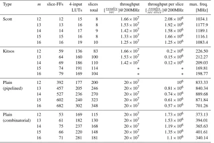
Table 2. Detailed Synthesis Result.
Type m slice-FFs 4-input slices throughput throughput per slice max. freq.
LUTs total [result ssec ]@200MHz [sec·sliceresult s ]@200MHz [MHz]
Scott 12 12 15 8 1.66×10⁷ 2.08×10⁶ 1034.1
13 13 16 8 1.53×10⁷ 1.92×10⁶ 1177.9
14 14 17 9 1.42×10⁷ 1.58×10⁶ 1189.1
15 15 16 8 1.33×10⁷ 1.66×10⁶ 1116.1
16 16 19 10 1.25×10⁷ 1.25×10⁶ 1083.4
Kitsos 12 59 136 83 1.66×10⁷ 0.2×10⁶ 226.50
13 64 160 100 1.53×10⁷ 0.15×10⁶ 212.27
14 69 186 110 1.42×10⁷ 0.12×10⁶ 209.03
15 74 191 114 ∗ ∗ 169.81
16 79 169 104 ∗ ∗ 198.77
Plain 12 392 177 200 20×107 106 833.33
(pipelined) 13 457 205 246 20×107 0.81×10⁶ 840.34
14 527 236 270 20×107 0.74×10⁶ 889.68
15 602 240 323 20×107 0.61×10⁶ 871.84
16 682 302 348 20×107 0.57×10⁶ 701.26
Plain 12 53 169 115 20×107 1.73×10⁶ 373.13
(combinatorial) 13 61 182 130 20×107 1.53×10⁶ 394.01
14 75 237 168 20×107 1.19×10⁶ 365.63
15 66 220 148 20×107 1.35×10⁶ 401.61
16 71 281 181 20×107 1.1×10⁶ 340.14
∗ :Maximum clock frequency was below 200 MHz.
consumed area, since those FFMs use up most of the hard-ware resources (see Sect. 3.4).
In order to achieve a well-balanced decoder design, we therefore suggest to employ two different FFM types in the decoder: combinatorial FFMs in the SGU and CSU, and small pipelined FFMs in the KES. This setup will exploit the benefits of both FFM types and reduce the overall area of the decoder, by only adding an insignificant amount of total latency.
5 Conclusions
Finite field multiplications are key in many technical applica-tions, particularly in decoding BCH codes. In this work we have investigated available pipelined architectures with re-spect to scalability, throughput and area consumption on FP-GAs. We have implemented and synthesized those designs for a common target device, a Xilinx Virtex-4 XC4VLX100 FPGA. Our implementations have been fully verified in a hardware-software co-simulation. We have evaluated and compared the selected architectures and show that for the choosen effiency metric the Scott-multiplier features in prin-ciple the best performance. For application of the considered multipliers in a DVB-S2 BCH decoder the Kitsos-multiplier
is outperformed by the other multipliers, despite the inher-ent architectural flexibility of the Kitsos-multiplier. Further-more, we conclude that the key equation solver part can profit most from pipelined finite field multipliers, and that simple combinatorial multipliers provide a higher benefit in the syn-drome computation and the Chien search.
References
Ahlquist, G. C., Nelson, B. E., and Rice, M.: Optimal Finite Field Multipliers for FPGAs, in: FPL ’99: Proceedings of the 9th In-ternational Workshop on Field-Programmable Logic and Appli-cations, pp. 51–60, Springer-Verlag, London, UK, 1999.
Bose, R. C. and Ray-Chaudhuri, D. K.: On a class of
er-ror correcting binary group codes, Inform. Control, 3, 68–79, doi:10.1016/S0019-9958(60)90287-4, 1960.
Bossert, M.: Kanalcodierung, B. G. Teubner Stuttgart, 2nd edn., 1998.
Chen, Z., Zhang, Y., Ying, Y., Wu, C., and Zeng, X.: An Area-Efficient and Degree-Computationless BCH Decoder for DVB-S2, in: Proceedings of the IEEE 8th International Conference on ASIC, (ASICON) 2009. , 489–492, doi:10.1109/ASICON.2009. 5351625, 2009.
Friedrichs, B.: Kanalcodierung, Springer Verlag Berlin Heidelberg, 1995, ISBN 3-540-59353-5.
C. de Schryver et al.: Design space exploration of FFMs for channel coding 181
Hocquenghem, A.: Codes correcteurs derreurs, Chiffres, 2, 147–56, 1959.
Kitsos, P., Theodoridis, G., and Koufopavlou, O.: An efficient re-configurable multiplier architecture for Galois field GF (2m), Mi-croelectr. J., 34, 975–980, 2003.
Liu, W., Rho, J., and Sung, W.: Low-Power High-Throughput BCH Error Correction VLSI Design for Multi-Level Cell NAND Flash Memories, in: Proceedings of the IEEE Workshop on Signal Processing Systems Design and Implementation, (SIPS) 2006. , 303–308, doi:10.1109/SIPS.2006.352599, 2006.
Scott, P., Tavares, S., and Peppard, L.: A Fast VLSI Multiplier for GF(2m), in: IEEE Journal on Selected Areas in Communications (J-SAC) 1986, 4, 62–66, 1986.
Zhang, B., Liu, D., Wang, S., Chen, X., and Liu, H.: Design and Im-plementation of Area-Efficient DVB-S2 BCH Decoder, in: Com-puter Engineering and Technology (ICCET), 2010 2nd Interna-tional Conference on, 3, V3–179–V3–184, doi:10.1109/ICCET. 2010.5485823, 2010.