Please cite this article as: M. Rezaiee-Pajand, A. Aftabi Sani, S. M. Hozhabrossadati, Free Vibration Analysis of a Six-degree-of-freedom Mass-spring System Suitable for Dynamic Vibration Absorbing of Space Frames, International Journal of Engineering (IJE), TRANSACTIONS A: Basics Vol. 30, No. 1, (January 2017) 30-39
International Journal of Engineering
J o u r n a l H o m e p a g e : w w w . i j e . i r
Free Vibration Analysis of a Six-degree-of-freedom Mass-spring System Suitable for
Dynamic Vibration Absorbing of Space Frames
M. Rezaiee-Pajand*, A. Aftabi Sani, S. M. Hozhabrossadati
Department of Civil Engineering, Ferdowsi University of Mashhad, Mashhad, Iran
P A P E R I N F O
Paper history:
Received 24 November 2016
Received in revised form 21 December 2016 Accepted 28 December 2016
Keywords: Space Frame
Dynamic Vibration Absorber Vibration Analysis
Six-Degree-of-freedom Mass-spring System Exact Solution
Finite Element Solution
A B S T R A C T
This study is concentrated on the natural frequencies and mode shapes of a simple three-member space frame coupled with a dynamic vibration absorber. The dynamic vibration absorber is modeled as a six-degree-of-freedom mass-spring system. For the first time, the free vibration of an elastic structure with a six-degree-of-freedom mass-spring system is found. Each member of the space frame has uniform mechanical and geometrical properties, but these may differ from one member to another. The exact result of this complex problem is obtained via analytical scheme and finite element method. All effects of the axial and torsional deformations and also in- and out-of-plane bending are taken into account. This formulation includes eighteen differential equations along with thirty six boundary and compatibility conditions. Comparison of the results by both approaches mentioned above, illustrates the accuracy of our solutions. Findings are useful benchmarks for the natural frequencies and mode shapes of the space frame coupled with a dynamic vibration absorber.
doi: 10.5829/idosi.ije.2017.30.01a.05
1. INTRODUCTION1
Frame systems are important structures which are used in many branches of engineering such as civil, mechanical and aerospace engineering. Vibrations of planar frames have received considerable attention in the literature [1-5]. On the other hand, space frame has received much less attention. This fact may be due to difficulty involved in the analysis of three-dimensional structures.
Dumir et al., used dynamic stiffness method for dynamic analysis of space frames under distributed harmonic loads [6]. Noorzaei presented a numerical solution for the modelling of the space frame-raft-soil system by means of finite element method [7]. Moon and Choi employed the finite element method for dynamic analysis of space frames [8]. Guo et al., proposed the formulation of dynamic reverberation-ray matrix analysis to study wave propagation of frames [9]. Tu et al., utilized the transfer dynamic stiffness matrix
1*Corresponding Author’s Email: [email protected] (M.
Rezaiee-Pajand)
method to study free vibration of space frames [10]. Minghini et al. used two-node locking-free Hermitian finite elements for analyzing vibration frequencies and mode shapes of pultruded FRP plane and space frames with semi-rigid joints [11]. Mei and Sha used wave-based as well as experimental methods to study vibrations in simple space frames [12]. Mei and Sha employed a wave-based method to investigate vibrations in built-up multi-story space frames [13].
All mentioned literature reviews showed that the free vibration of an elastic continuous structure joined by a mass-spring system up to three degrees of freedom has been investigated so far. To the authors' best knowledge, the free vibration analysis of space frame including mass-spring system and having six-degree-of-freedom has not been treated yet. This mass-spring system can be used as a realistic model for a dynamic vibration absorber. Therefore, the main objective of this paper is to fill this gap and present a simple straightforward method for analyzing the free vibration of space frames with an attached six-degree-of-freedom mass-spring system. As a result, this study is devoted to the free vibration of a space frame with three orthogonal members having a dynamic vibration absorber, which is shown in Figure 1. The dynamic vibration absorber is modeled as a six-degree-of-freedom mass-spring system. Each member of the frame has uniform mechanical and geometrical properties. To generalize the solution, these properties may differ from one member to another. The governing eigenvalue problem includes eighteen differential equations and thirty six boundary and compatibility conditions. In the presented formulation, all interactions of axial deformation, torsional deformation and in- and out-of-plane bending are considered. After solving the related eigenvalue problem, natural frequencies and mode shapes of the system are found. To verify the correctness of the authors' formulation, the exact solution of the problem is also obtained by the finite element method.
2. GOVERNING DIFFERENTIAL EQUATIONS OF SPACE FRAMES
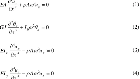
As mentioned previously, for free vibration analysis of space frames, in the most general case, the interaction of in-plane bending, out-of-plane bending, axial deformation and torsional deformation could be considered. Therefore, for a space frame member, the following differential equations describe the vibratory behavior of the member [13]:
2
2
2 0
x
x u
EA A u
x
(1)
2
2 0
2 0
x
x
GJ I
x
(2)
4
2
4 0
y
z y
u
EI A u
x
(3)
4
2
4 0
z
y z
u
EI A u
x
(4)
where ux, x , uy and uz are axial displacement, angular displacement, xy-plane transverse displacement
and xz-plane transverse displacement, respectively. In addition, x is the position along the member axis, t time,
E Young's modulus, A cross-sectional area, G the shear modulus, J the polar moment of the circular member,
0
I the mass moment of inertia per unit length of the member,
volume mass density, Iz the area moment of inertia of cross-section of the section about z-axis andy
I
the area moment of inertia of cross-section of the section about the y-axis. For circular members, the following relations hold:4
4 0
;
4 ;
2 z y
R
I I I I
R
I J J
(5)
(a)
(b)
(c)
(d)
in which R is the radius of the member. It should be mentioned that no warping occurs for the circular sections.
The solutions of Equations (1)-(4) have the next appearance:
1 2
3 4
5 6 7 8
9 10 11 12
sin cos
sin cos
sin cos sinh cosh
( )
( )
( )
sin cos sinh c h
) os
(
a a
t t
b b b b
b b x x b y z b
u x c
x c
u x c c
u x c
x c x
x c x
x c x x c x
x c x c x c x
(6)
where c1 to c12 are unknown constants, which are to be determined. The parameters
a,
t and
b have the coming form: 2 2 2 2 4 2 a t b A EA AR GJ A EI (7)In the next section, the eigenvalue problem governing the vibratory behavior of the mentioned space frame is formulated.
3. FORMULATION OF EIGENVALUE PROBLEM
This section presents the eigenvalue problem which governs the space frame with attached dynamic vibration absorber. The dynamic vibration absorber is modeled as a six-degree-of-freedom mass-spring system, which is connected to the space frame by means of six springs. This system has three translational springs of stiffness K1, K2 and K3 in the
x
, y andz
directions, respectively, and three rotational springs of stiffness K4, K5 and K6 in thex
, y andz
directions, correspondingly. Figure 1 demonstrates a schematic diagram of the mechanical system under study.The related eigenvalue problem includes governing differential equations and boundary and compatibility conditions. It should be noted that upon solution of this problem, the eigenvalues and eigenfunctions of the problem which are the frequency parameters and mode shapes of the system are in hand. In the subsequent subsections, the differential equations and boundary and compatibility conditions are given.
3. 1. DIFFERENTIAL EQUATIONS As mentioned in Section 2, considering the interaction of in-plane bending, out-of-plane bending, axial deformation and torsional deformation, four differential equations are needed to study the behavior of a space frame member. These four differential equations are introduced by
Equations (1)-(4). Totally, twelve differential equations exist for the three-member space frame and six differential equations govern the behavior of the mass-spring system. Using index notation, the differential equations of the space frame may be written in the shapes shown hereunder:
2
2
2 0
xi
i i i i xi
u
E A A u
x
(8) 2 2 0 2 0 xi
i i i xi
G J I
x (9) 4 2 4 0 yi
i i i i yi u
E I A u
x
(10) 4 2 4 0 zi
i i i i zi
u
E I A u
x
(11)
where i1, 2,3 indicates the member number. The solutions of Equations (8) - (11) have the following forms:
1 1 2 1
3 1 4 1
5 1 6 1 7 1 8 1
9 1 10 1 11 1 12 1
13 2 14 2
15 2 1 6 1 1 1 2 2 1 sin cos sin cos
sin cos sinh cosh
sin cos sinh cosh
sin cos ( ) ( ) ( ) ( ) ( si ) n ( ) a a t t x x
b b b b
b b y b b a a x x t z
u x c
x c
u x c c
u
x c x
x c x
x c x x c x
x c x x c x
x c x
x c
x c c
u x c
x c 2
17 2 18 2 19 2 20 2
21 2 22 2 23 2 24 2
25 3 26 3
27 3 28 3
29 3 30 3
2 2 3 3 31 3 cos
sin cos sinh cosh
sin cos sinh cosh
sin cos sin c ( ) ( ) ( ) os sin cos ( ) ) s ( y z x x y t
b b b b
b b b b
a a
t t
b b
x
x c x x c x
x c x x c
u x c c
u x c c
u x c
x c
u x c
x
x c x
x c x c x c x
3 32 3
33 3 34 3 3
3 35 3 36
inh cosh
sin cos sinh c s
) o h
(
b b
b
z b b b
x c x
x c
u x c x c x c x
(12) in which
2 2 2 2
1 1 1 1 1 1
4
1 1 1
1 1 1 1 1
2 2 2 2
2 2 2 2 4 2 2
2 2 2
2 2 2 2 2
2 2 2 2
3 3 3 3 3 3
4
3 3 3
3 3 3 3 3
; ; 2 ; ; 2 ; ; 2
a t b
a t b
a t b
A R A
E G J E I
A R A
E G J E I
A R A
E G J E I
(13)
It is observed that thirty six unknown constants are presented in Eq. (12). Therefore, thirty six boundary and compatibility conditions should be specified. The differential equations of the mass-spring system will be introduced in Section 4.
displacements along with in-plane and out-of-plane rotations are zero. These lead to the following mathematical relationships:
1 1 2 2 3 3
1 1 2 2 3 3
1 1 2 2 3 3
1 1 2 2 3 3
1 1 2 2 3 3
1 1 2 2 3 3
( ) 0 ; ( ) 0 ; ( ) 0
( ) 0 ; ( ) 0 ; ( ) 0
( ) 0 ; ( ) 0 ; ( ) 0
( ) 0 ; ( ) 0 ; ( ) 0
( ) 0 ; ( ) 0 ; ( ) 0
( ) 0 ; ( ) 0 ; ( ) 0
x x x
x x x
y y y
z z z
y y y
z z z
u L u L u L
L L L
u L u L u L
u L u L u L
u L u L u L
u L u L u L
(14)
2) Equilibrium of forces at the intersecting joint. The shear forces and axial forces of the frame must be in equilibrium with the forces of the springs of the mass-spring system in the x, y and z directions. Using Newton's second law results in the following equations:
1 2
1 1 2 2 3 3
2 2 3 3 1 1
3 3
3 1
2 3 1 2
3 2 2 2 11 1 3
(0) (0) (0) 0
(0) (0) (0) 0
(0) (0) (0) 0
x y y
x z y
x z z
E A E I E I
E A E I E I
E
u u u F
u u u F
u E u u F
A I E I
(15)
in which F1, F2 and F3 are the forces of the translational springs of the mass-spring system in the x, y and z
directions, respectively. These forces can be written as:
1 1 1
2 2 1
3 3 1
(0) (0) (0) x x y y z z
F K u u
F K u u
F K u u
(16)
where
u
x ,u
y andu
z are the displacements of the mass-spring system in the x, y and z directions, respectively. Furthermore, K1,2
K and K3 indicate the stiffness of the translational springs of the mass-spring system in the x, y and z directions, respectively.
3) Equilibrium of moments at the intersecting joint. The bending moments and torques of the space frame members and moments of the rotational springs of the mass-spring system must be self-equilibrated in the x, y
and z directions. Writing Newton's second law gives the coming equalities:
1 2 3 1
2 3 1 2
3
1 1 2 2 3 3
2 2 3 3 1 1
3 3 1 1 1 2 2 2 3
(0) (0) (0) 0
(0) (0) (0) 0
(0) (0) (0) 0
x y y
x z y
x z z
u
G J E I E I
G J E I E I
G J E I
u M
u u M
u E I u M
(17)
in which, M1, M2 and M3 are the moments of the rotational springs of the mass-spring system in the x, y
and z directions, respectively. They are defined as:
1 4 1
2 5 1
3 6 1
(0) (0) (0) x x y y z z M K M K M K (18)
where K4, K5 and K6 demonstrate the stiffness of the rotational springs of the mass-spring system in the x, y
and z directions, respectively.
4) Compatibility of rotations and angular displacement at the intersecting joint can be expressed as:
1 2 1 3
3 1 1 2
2 3 2 1
(0) (0) ; (0) (0)
(0) (0) ; (0) (0)
(0) (0) ; (0) (0)
y y y x
y z z x
z z z x
u u u
u u u
u u u
(19)
5) Compatibilities of displacements at the intersecting joints are satisfied by:
1 2 1 3
2 1 1 3
3 1 1 2
(0) (0) ; (0) (0)
(0) (0) ; (0) (0)
(0) (0) ; (0) (0)
x y x y
x y y z
x z z z
u u u u
u u u u
u u u u
(20)
All thirty six boundary and compatibility conditions given by Equations (14), (15), (17) and (19), (20), along with twelve differential equations expressed in Equations (8)-(11) form the governing eigenvalue problem for this space frame. In order to use the compatibility conditions of the forces and moments of the intersecting structural joint, given by Equations (15) and (17), the values of
F
1,F
2 andF
3 along with M1,2
M and M3 should be found. In the next section, these
forces and moments are obtained, considering the behavior of the mass-spring system.
4. MASS-SPRING SYSTEM FORMULATION
The mentioned oscillator is modeled as a six-degree-of freedom mass-spring system. In this section, six differential equations governing the vibratory behavior of the mass-spring system are investigated. To formulate the mass-spring system, the Newton's second law of motion is employed. Writing the translational Newton's second law of motion in the
x
direction, i.e.,x x
F Ma
, gives the following equality:1 x
F Mu (21)
in which, M is the mass of the dynamic vibration absorber. Substituting Equations (16) into Equation (21) yields:
1 x1(0) x x
K u u Mu (22)
or
1 1 1(0)
x x x
Mu K u K u (23)
Using
u
x
Ue
i t results in: 21 1 1(0)
x x x
Mu K u K u
(24)
which gives 1 1 2 1 (0) x x K u u
K M
Defining 1 1
1 1 3 1 1 1
1 ;
E I
K k M A L
L
(26)
Equation (25) becomes:
1 1 1 3 1
1
2 1 1
1 3 1 1 1
1 (0) x x E I k u L u E I
k A L
L
(27)
where
k
1 denotes the stiffness of the translational spring of the dynamic vibration absorber in thex
direction. It should be added that
is a constant. Equation (27) can be simplified as:1 1 4
1 1 1
(0) ( ) x x b k u u
k
L
(28)
Likewise, it can be shown that the following relations hold for
u
y andu
z:2 1 3 1
2 2 2 3 (0) (0) ; y z y z
K u K u
u u
K M K M
(29)
These relations can be written in the form:
2 1 3
4 1 1 2
2 3 1 1
2 2 1 3 1
3 4 1 1 3
3 3 1 1
3 3 1 (0) ( ) (0) ( ) y y b z z b k u u
E I L
k L
E I L k u u
E I L
k L
E I L
(30) in which: 3 3 2 2
2 2 3 3 3 3
2 3
; E I
E I
K k K k
L L
(31)
In Equation (31),
k
2 andk
2 are the stiffness of the translational springs of the dynamic vibration absorber in the y andz
directions, respectively. The three remaining equations are obtained using the rotational form of Newton's second law of motion, i.e.,
M I0,where
I
0 is mass moment of inertia. Findings are:4 1 2 4 0 5 1 2 5 0 6 1 2 6 0 (0) (0) (0) x x y y z z K K I K K I K K I (32) Using:
1 1 2 2
4 4 5 5
1 2
3 3 3
6 6 0 1 1 1
3 ;
;
E I E I
K k K k
L L
E I
K k I A L
L
(33)
The values of
x,
y and
z take the following form: 4 14
4 1 1
5 1
4 1 1 2
5 1 1
2 2 1 6 1
4 1 1 3
6 1 1
3 3 1 (0) ( ) (0) ( ) (0) ( ) x x b y y b z z b k k L k E I L
k L
E I L k E I L
k L
E I L (34)
where k4, k5 and k6 are the stiffness of the rotational springs of the dynamic vibration absorber. Furthermore, is a constant. The expressions obtained for degrees of freedom of the mass-spring system can be substituted into Equations (16) and (18). Consequently, the boundary and compatibility conditions introduced previously can be utilized in the following sections. It is worth mentioning that the six natural circular frequencies of the mass-spring system, when it is not coupled with the space frame, have the following shapes: 4 1 4 1 0 5 2 2 5 0 3 6 3 6 0 ; K K I M K K M I K K M I (35)
5. EIGENVALUES AND EIGENFUNCTIONS
In order to obtain the eigenvalues and eigenfunctions of the problem under study, the following strategy is employed. According to the boundary and compatibility conditions, the required derivatives of functions uxi, xi,
yi
u
and uzi should be calculated. Afterward, these derivatives, as well as functions uxi,
xi,u
yi and uzi, are substituted in the thirty six boundary and compatibility conditions, which are expressed by Equations (14), (15), (17), (19) and (20). This action leads to form the coming homogeneous system of algebraic equations with c1 toc
36 as unknowns:To have a nontrivial solution, the determinant of the coefficient matrix must be equal to zero, as it is demonstrated in the following relationship:
0
A (37)
Calculating the determinant yields the frequency equation of the problem under study. Close attention should be paid to the fact that the resulting frequency equation has nine unknowns, i.e.,
a1,
t1,
b1,
a2,2
t
,
b2,
a3,
t3 and
b3. In order to have the frequency equation with a single unknown, i.e.,
b1, the following relations are used:2 2
2 2
1 1 1
1 1 1 1
1
2 2
2 2
2 2 2 2 1 2
4
2 2 2 2 2 1
2 1 2 1
2 2
2 2
3 3 3 3 1 3
4
3 3 3 3 3 1
3 1 3 1
;
2 2
; ;
2 2
; ;
2 2
a b t b
a b t b b b
a b t b b b
R E R
G
R E R E R
G E R
R E R E R
G E R
(38)
Having these, the resulting complicated frequency equation can be numerically solved using the well-known Newton-Raphson method. Consequently, upon solution of the frequency equation, the values of
b1s are in hand. Then, Equation (13) is utilized to find the natural circular frequencies of the space frame, i.e.,
. Finally, substituting the
b1s into the matrix Equation (29), the mode shapes of the mechanical system under study are obtained. As a second way, a finite element solution is developed. Comparing the results obtained by both exact and numerical solutions demonstrates the accuracy of our formulation.6. Finite Element Formulation
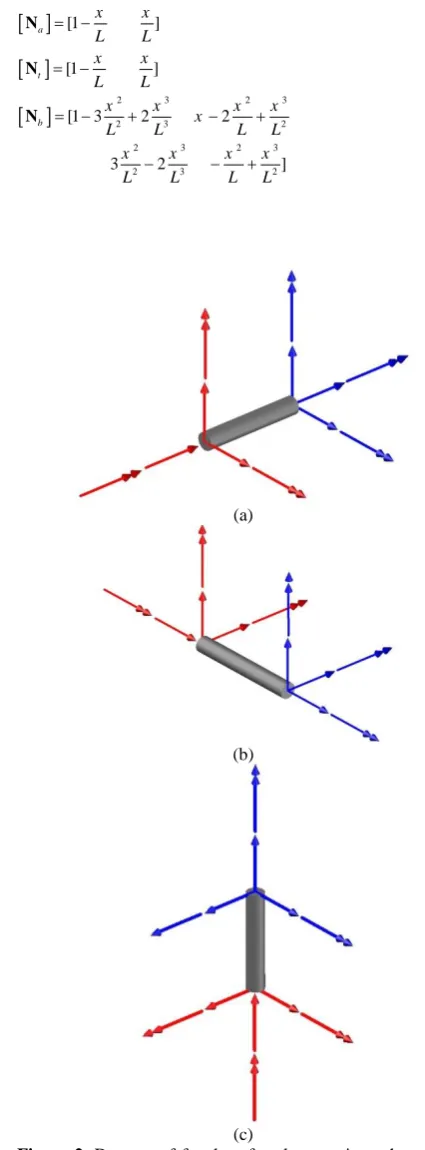
A finite element solution is presented in this section for the complex problem under study. Figure 2 shows the degree of freedom of elements for each member of the space frame. It is observed that each node has six degrees of freedom, namely, three translational and three rotational. Therefore, the total nodal displacements are given in the equation below:
Txi yi zi xi yi zi xj yj zj xj yj zj
u u u u u u
D (39)
All displacement functions can be written using the shape functions:
x a xi xj
x t xi yi
y b yi yi yj yj
z b zi zi zj zj
u u u
u u u
u u u
N N N N
(40)
where
Na ,
Nt and
Nb are the shape functions for axial displacement, torsional displacement and in- and out-of-plane bending. Herein, the well-known Hermit shape functions are used with following appearance:
2 3 2 32 3 2
2 3 2 3
2 3 2
[1 ]
[1 ]
[1 3 2 2
3 2 ]
a
t
b
x x
L L
x x
L L
x x x x
x
L L L L
x x x x
L L L L
N
N
N
(41)
(a)
(b)
(c)
Using the shape functions and their needed derivatives, the stiffness and mass matrices for each member are found. It should be pointed out that the final stiffness and mass matrices have (ndof 6) (ndof 6) entries, where ndof indicates the number of degrees of freedom of the space frame. This modification is due to the interaction of the six-degree-of-freedom mass-spring system and the space frame. In order to obtain the natural frequencies of the space frame, the following equation of motion should be solved:
M D
K D 0 (42)Assuming harmonic motion, one obtains:
i te
D D (43)
Substituting this equation into Eq. (36) esults in:
K 2 M
D
0(44) For a nontrivial solution:
2
0
K M (45)
From the last system of equations, the natural frequencies of the space frame under study may be calculated.
7. NUMERICAL RESULTS
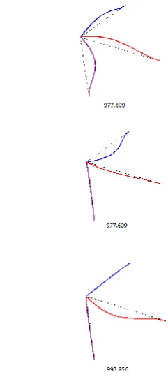
This section is devoted to solve sample problems of the free vibration of the space frame with and without attached mass-spring system. Figure 3 indicates the first three circular frequencies, i.e.,
and three-dimensional mode shapes of the space frame without mass-spring system, with steel members, having properties of1 2 3 0.1 m
R R R , L1L2L32 m,
11
1 2 3 2 10 Pa
E E E ,
3 1 2 3 7850 kg/m
and 1 230.3. It should be noted that the ratio L R/ 20 is selected for each member. This limitation is usually required for using the Euler-Bernoulli beam theory.
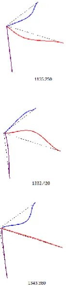
In order to investigate the effect of the member lengths on the natural frequencies of the system, the length of the third member is assumed to be L36 m. The first eight circular frequencies and three-dimensional mode shapes of the space frame in this case for R1R2R30.1 m, L1L22 m, L36 m,
11
1 2 3 2 10 Pa
E E E , 3
1 2 3 7850 kg/m
and 1 230.3 are indicated in Figure 4. It is observed that by increasing the length of the third member from 2m to 6m, the natural frequencies of the space frame is dramatically decreased. For instance, the first natural frequency decreases from 977.609 to 141.101 when L3 increases from 2 m to 6 m.
Figure 3. The first three natural frequencies and mode shapes of the bare space frame
Figure 5 may be advantageous for studying the effect of the radius of members on the frequencies of the space frame. In this figure, the first eight natural frequencies and mode shapes of the mechanical system under study for R1R20.1 m, R30.2 m L1L2L32 m,
11
1 2 3 2 10 Pa
E E E , 3
1 2 3 7850 kg/m
and 1 23 0.3 are illustrated. As expected, increasing the stiffness of the space frame, by increasing the radius of the third member, results in a boost in the natural frequencies of the frame. For instance, the fundamental natural frequency of the space frame increases from 977.609 to 1135.250 when the radius of the third member increases from 0.1m to 0.2m.
At this stage, a space frame with clamped ends and general properties of R10.1m, R20.2 m,
3 0.3 m
R , L12 m, L2 4 m, L35 m, 11
1 2 3 2 10 Pa
E E E , 3
1 2 3 7850 kg/m
,
1 0.2
and 230.3 is considered. The first eight natural frequencies and mode shapes of the frame are presented in Figure 6.
Figure 4. The first three natural frequencies and mode shapes of the bare space frame with different lengths
Figure 5. The first three natural frequencies and mode shapes of the bare space frame with different raduis
The properties of the frame are the same as the one in Figure 6. The properties of the dynamic vibration absorber are 10, 10, and
k
3 has different values. It should be noted that the first five natural frequencies of the system are zero. This is because the stiffness of five springs of the dynamic vibration absorber are assumed zero. Furthermore, the value of the sixth natural frequency, which can be considered as the fundamental one, has decreased from 447.034 to 287.177 for k31.For k35 and k310 the fourth and fifth natural frequencies are changed. Other natural frequencies are almost the same as the bare space frame. It can be concluded that increasing the stiffness of the spring increases the value of the natural frequencies.
Figure 6. The first three natural frequencies and mode shapes of the bare space frame with different properties
TABLE 1. The values of natural frequencies of the coupled frame for different values of
k
33
k
Mode number1 2 3 4 5
1 287.177 447.034 460.329 538.334 680.248
5 447.034 460.327 538.334 640.338 680.724
In order to study the effect of the mass of the dynamic vibration absorber, Table 2 is used. The natural frequencies of the system are given for the properties of the previous example in Table 1, but for k35 and different values of
and . From Table 2, it is seen that increasing the mass of the dynamic vibration absorber decreases the value of the fundamental natural frequency. For instance, the value of the fundamental natural frequency decreases from 447.034 to 370.03, when
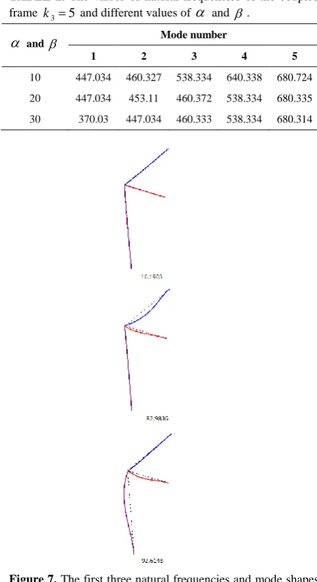
and increase from 20 to 30.Finally, the coupled frame with the properties of the bare frame in Figure 7 and k11, k218, k38,
4 2
k , k515, k612, 5 and 30 are considered. The first eight mode shapes of the systems are depicted in Figure 7.
TABLE 2. The values of natural frequencies of the coupled frame k35 and different values of
and .
and Mode number1 2 3 4 5
10 447.034 460.327 538.334 640.338 680.724
20 447.034 453.11 460.372 538.334 680.335
30 370.03 447.034 460.333 538.334 680.314
Figure 7. The first three natural frequencies and mode shapes of the coupled space frame with different properties
Comparing Figures 6 and 7, it can be concluded that the natural frequencies of the coupled system are significantly changed. These results show that one can obtain the optimum value of the natural frequencies of the system by adjusting the values of the system parameters.
8. CONCLUDING REMARKS
Exact solutions for free vibration analysis of space frames with clamped and free ends joined by a dynamic vibration absorber are proposed in this article. A coupled three-dimensional formulation, including the effects of axial deformation, torsional deformation, in- and out-of-plane bending is carried out. This action leads to a governing boundary value or an eigenvalue problem. The mathematical model includes eighteen differential equations and thirty six boundary and compatibility conditions. All of mentioned formulations are derived in detail. Furthermore, a general finite element solution is presented and dynamic properties of the space frame are found. The natural frequencies and three-dimensional mode shapes of the system are calculated for different values of member mechanical and geometrical properties. The authors' results can be used as a benchmark problem to study the free vibration analysis of space frames. It is shown that increasing the stiffness of the dynamic vibration absorber increases the values of the natural frequencies of the coupled frame. Moreover, increasing the mass or mass moment of inertia of the dynamic vibration absorber decreases the values of natural frequencies of the space frame. The optimum value for the natural frequencies can be obtained by tuning the values of the properties of the dynamic vibration absorber, such as, stiffness of springs or mass.
9. REFERENCES
1. Albarracín, C.M. and Grossi, R.O., "Vibrations of elastically restrained frames", Journal of sound and vibration, Vol. 285, No. 1, (2005), 467-476.
2. Grossi, R. and Albarracín, C., "A variational approach to vibrating frames", Proceedings of the Institution of Mechanical
Engineers, Part K: Journal of Multi-body Dynamics, Vol. 221,
No. 2, (2007), 247-259.
3. Rezaiee-Pajand, M., Bambaeechee, M. and Sarafrazi, S., "Static and dynamic nonlinear analysis of steel frame with semi-rigid connections", International Journal of
Engineering-Transactions A: Basics, Vol. 24, No. 3, (2011), 203.
4. Rezaiee-Pajand, M. and Khajavi, R., "Vibration analysis of plane frames by customized stiffness and diagonal mass matrices", Proceedings of the Institution of Mechanical Engineers, Part C: Journal of Mechanical Engineering
Science, (2011), 2848- 2863.
solution and modification of the characteristic matrices", To Be
Submitted, (2012).
6. Dumir, P., Saha, D. and Sengupta, S., "Dynamic stiffness method for space frames under distributed harmonic loads",
Computers & Structures, Vol. 45, No. 3, (1992), 495-503.
7. Noorzaie, J., "Interactive analysis of space frame raft soil system", International Journal of Engineering, Vol. 8, No. 3, (1995), 133-146.
8. Moon, D. and Choi, M., "Vibration analysis for frame structures using transfer of dynamic stiffness coefficient", Journal of
Sound and Vibration, Vol. 234, No. 5, (2000), 725-736.
9. Guo, Y., Chen, W. and Pao, Y.-H., "Dynamic analysis of space frames: The method of reverberation-ray matrix and the orthogonality of normal modes", Journal of Sound and
Vibration, Vol. 317, No. 3, (2008), 716-738.
10. Tu, T.-H., Yu, J.-F., Lien, H.-C., Tsai, G.-L. and Wang, B.,
"Free vibration analysis of frames using the transfer dynamic stiffness matrix method", Journal of Vibration and Acoustics, Vol. 130, No. 2, (2008), 024501.
11. Minghini, F., Tullini, N. and Laudiero, F., "Vibration analysis of pultruded frp frames with semi-rigid connections", Engineering
Structures, Vol. 32, No. 10, (2010), 3344-3354.
12. Mei, C. and Sha, H., "Analytical and experimental study of vibrations in simple spatial structures", Journal of Vibration
and Control, (2015), DOI: 10.1177/1077546314565807.
13. Mei, C. and Sha, H., "An exact analytical approach for free vibration analysis of built-up space frames", Journal of
Vibration and Acoustics, Vol. 137, No. 3, (2015),
310051-3100512.
14. Banerjee, J., "Free vibration of beams carrying spring-mass systems− a dynamic stiffness approach", Computers &
Structures, Vol. 104, (2012), 21-26.
Free Vibration Analysis of a Six-degree-of-freedom Mass-spring System Suitable for
Dynamic Vibration Absorbing of Space Frames
M. Rezaiee-Pajand, A. Aftabi Sani, S. M. Hozhabrossadati
Department of Civil Engineering, Ferdowsi University of Mashhad, Mashhad, Iran
P A P E R I N F O
Paper history:
Received 24 November 2016
Received in revised form 21 December 2016 Accepted 28 December 2016
Keywords: Space Frame
Dynamic Vibration Absorber Vibration Analysis
Six-Degree-of-freedom Mass-spring System Exact Solution
Finite Element Solution
ديكچ ه
لکش و یعیبط یاهدماسب ،شهوژپ نیا رد تلاح یاه
هدننک بذج کی اب ریگرد هداس ییاضف باق کی یناسون ناسون ی
هب ایوپ یم تسد هدننک بذج .دنیآ هناماس کی اب یایوپ ناسون ی
هجرد شش ی یم وگلا رنفـمرج یدازآ ی
نیتسخن یارب .دوش
هزاس کی دازآ ناسون ،راب شک ی
هناماس کی اب ناس ژیو باق وضع ره .دش دهاوخ یسررب یدازآ هجرد شش ی
یگ یاه
کی یسدنه و یکیناکم یگژیو نیا اما ،دراد تخاون
یم اه هلأسم نیا قیقد خساپ .دشاب توافتم یرگید هب تبسن دناوت ی
هار اب هدیچیپ هویش و یلیلحت راک
یم رارق سرتسد رد دودحم یاهءزج ی لکشرییغت یاهرثا .دریگ
هب یشچیپ و یروحم یاه
هب هحفص نورب و هحفص نورد شمخ هارمه ک
یم را هطبار .دنور هلداعم هدجه یاراد هلأسم یزاس شش و یس و لیسنارفید ی
هسیاقم اب .تسا یراگزاس و یزرم طرش خساپ ی
هویش یتسرد ،شور ود یاه یم راکشآ ناگدنسیون یداهنشیپ یاه
نیا .ددرگ
هجیتن یم اه لکش و یعیبط یاهدماسب یارب هناشن گنس ناونع هب دنناوت ق یناسون تلاح یاه
با هدننک بذج اب ییاضف یاه ی