Train Operation Control on-based of
Logical-Linguistic Model
K.I. Yurenko
1,*, P.A. Kharchenko
2, E.I. Fandeev
3and I.K. Yurenko
41
Rostov State Transport University, 2, sq. Rostovskogo Strelkovogo Polka Narodnogo Opolcheniya, Rostov-on-Don, Russia, 344038, Russia
2
Join stock company "Russian Railways", the operational locomotive depot Likhaya, 1, district Likhovsky, Kamensk-city, Rostov region, 347820, Russia
3
Platov South-Russian State Polytechnic University (NPI), 132, Prosvesheniya Street, Novocherkassk, 346428, Russia
4
independent researcher, 36, Gvardeyskaya Street, Novocherkassk, 346405, Russia
Abstract
The article presents a new approach to control of train movement based on a combination of terminal (finite) and fuzzy control methods using a logical-linguistic model whose numerical parameters are determined on the basis of search optimization and simulation modeling. The results of computational experiments are presented and given recommendations to the application and further development of the proposed approach. In particular, the proposed logical-linguistic model can be used in the construction of on-board systems of suburban electric trains.
Keywords: on-board control system, suburban electric trains, passenger train, fuzzy logic, logical-linguistic simulation, computing experiment, autodriver.
Received on 31 May 2018, accepted on 26 August 2018, published on 28 January 2019
Copyright © 2019 K.I. Yurenkoet al., licensed to EAI. This is an open access article distributed under the terms of the Creative Commons Attribution licence (http://creativecommons.org/licenses/by/3.0/), which permits unlimited use, distribution and reproduction in any medium so long as the original work is properly cited.
doi: 10.4108/eai.13-7-2018.156388
*Corresponding author. Email: [email protected]
1. Introduction
The automation of train traffic control is one of the main ways to improve its safety, save energy resources, improve the working conditions of locomotive crews with strict observance of the traffic schedule [1,2]. The system of train auto-driving must solve the problem of determining and realizing the optimal trajectory of motion in real time mode taking into account the perturbations [3]. This task belongs to the class of terminal (or finite, according Bellman) control.
The results of its solution on the basis of various methods and approaches, as well as the analysis of the experience of driving trains by the drivers, made it possible to determine the general form of the optimal trajectory of the train and the principles of design an automatic train operation system (ATO) [4-12]. In general, such a trajectory
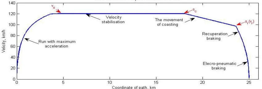
includes acceleration sections with maximum acceleration, speed stabilization, coasting (inertia motion), electrodynamic (recuperative or rheostatic) and mechanical (pneumatic or electro-pneumatic) braking (Fig. 1). In this case, the ATO is most often realized as a two-loop subordinate control system, in which the external circuit is responsible for controlling the travel time, while the internal circuit contains a speed controller [4,5,7].
Further development of systems of this class can be associated with their intellectualization, i.e. application in control loops of methods and models of artificial intelligence. Thus, the possibilities of using the math-based apparatus of fuzzy logic to solve the problem of automating the control of train brakes were considered in [13-16]. This paper presents the author's proposed approach to control the movement of trains on the basis of a combination of methods terminal (finite) and fuzzy control.
EAI Endorsed Transactions
2
Figure 1. The structure of the optimal trajectory of the train movement:
v
s- velocity of stabilization; cs
- coordinate of start coasting;s
r(
v
r)
- coordinate or velocity of start recuperation brakingIn this case the ATO is constructed as a two-loop feedback system with elements of prediction and approximation of the dependence of the stabilization speed on the motion time. As a regulator of time motion used logical-linguistic model, the numeric parameters being determined on the basis of search optimization and simulation modeling.
The results of simulation modeling allow us to recommend the developed logical and linguistic model of train traffic control for the solution of problems of automation of electric train control, which are characterized by short distances with an explicit structure of the optimal trajectory of motion, presented in Fig.1.
2. Simulation model of train movement
2.1. Mathematical model
Dynamics of electric rolling stock taking into account the distributed mass of the train in accordance with the basic provisions of the theory of electric traction [11, 12] can be described by the following system of equations:
= (∑ + ∑ )/((1 + )( + ∑ )) ; (1)
∑ = ( − − ); (2)
= ( , , ) ; (3)
= ( ( ), ); (4)
= ( ( ( ), ( )]; (5)
∑ = ∑ ( ) + , − ( ) ; (6)
( ( , ), ) = Ф( в) + ; (7)
| = Ф(в) ; (8)
= 1000 ∑ ( ( ) ( )) ; (9)
( ) =
( + + ) , = 1. .
+ ) , = 1. . ; (10)
, = , + , , (11)
where: - the coordinate of the path; - velocity; ∑ and - ∑ the sum of regulated and unregulated external forces: , , - traction power, electrical and pneumatic automatic braking; , , - main, additional and the auxiliary resistance to movement; and respectively the number of locomotives and cars; and the weight of the locomotive and wagon; - weight of wagon on one axis; – coefficient of inertia of rotating parts; – , the voltage in the contact system and the engine; = ( , ) -control of traction system; – ratio; Ф magnetic flux;
number of engines; – the efficiency of the locomotive; - the force of pressure on the brake pads; -the pressure in -the brake cylinders; – the friction coefficient; , , , , , , - coefficients depending on the type of rolling stock; – acceleration of free fall; and – the resistance of slopes and curves the path; – the length of the j-th unit of rolling stock; – a set of determinants ; , , function control of traction, regenerative and mechanical brake.
2.1. Simulation in Matlab/Simulink
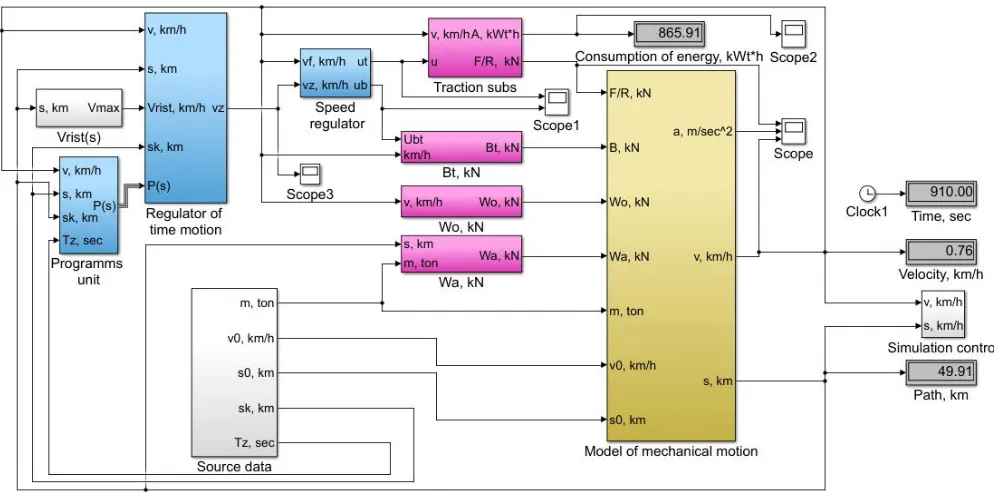
To taking into account of the ratios (1) - (11) developed a simulation model for the train movement in Matlab/Simulink, the block-scheme of which is shown in Fig. 2. Here are the basic functional units of the model: simulation traction, recuperation and mechanical braking; forces of the main and additional resistances to motion; blocks of modeling the mechanical motion of a train, input data, restrictions of speed, regulation of speed and time motion and optimal programs; auxiliary units for imaging parameters, management of computing experiment, calculation of power consumption etc..
Figure 2. The block-scheme of simulation model of train movement in Matlab/Simulink The developed simulation model allows to study the
traffic control of suburban electric trains, as well as passenger trains. On its basis, the authors developed an algorithm for searching for energy-optimal modes of train driving over a given area, which allows finding optimal parameters , , ( ), defining the vector control function = ( , , ); = ( , , , ) under which the isoperimetric condition is fulfilled (the predetermined travel time over the way): ( , , ) = ∫ / ; and provides optimization in terms of the quality functional,
= ( , , ) = ∫ ( − ) ⇒ ,
where the total energy consumption for traction; , efficiency electric train (electric locomotive) in the mode of traction and recuperation; and и the coordinates of the beginning and end of the path.
3. Automatic train operation (ATO)
system
3.1. Functional diagram of ATO
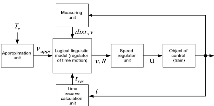
In this paper, the following functional diagram of the ATO system is suggested - Fig. 3.
It is a system of subordinate regulation, in which the inner loop ensures speed control, and external – control of time motion, for which it is proposed to use a logical-linguistic model. Measurement unit of designed to determine the current speed and the distance to the end of path dist. The time reserve calculation unit determines the
available time t for the implementation of energy-saving modes of coasting and regenerative braking taking into account timetable and based on the assumption that the movement in current time will be with the current speed, and braking with maximum acceleration . For this purpose, the following design relations:
= −
∙
the estimated braking distance;
= −
∙
calculated braking time; = − - the length of the part of motion with constant speed (v);
= / ∙ - motion with constant ; = − - the remaining time of motion; - specified schedule time motion; = − − - reserve of time motion; = 25920; = 3.6; = 3600 the coefficients of the agreement of the dimensions of the quantities included in the calculated ratio (acceleration, velocity, path).
The approximation unit is suitable for approximate calculations of optimal speed stabilization . It is defined to take into account on values of corresponding to two conditionally-optimal trajectories obtained by simulation or calculation. In the first case, we assume the movement at the upper speed limit , and the second is conventionally taken as the speed limit . So, if the maximum permissible speed = 120 km/h, it can be taken as 80 km/h. For each of the two values should to find the minimum possible time of motion (optimization on minimum time motion): = ( ) and =
( ).
4
Figure 3. The suggested functional diagram of automatic train operation system
To determine these dependencies use the assumption that the movement is performed in three modes: acceleration with maximum , value of speed stabilization speed , movement with the maximum deceleration ,
= + + =
= 1 + − − − + − ;
= −
∙ the length of the acceleration path;
= −
∙ .
Using the obtained dependence can be determined numerically. To obtain the analytical dependence of the integral in the first term can be replaced by the expression:
= ( )
0.5 ( ( ) − ( )),
where ( ) and ( ) are the values of traction at the beginning of the movement and the end of acceleration in accordance with the traction characteristics of the locomotive, - the train weight, - the speed at the beginning of the movement.
After calculating and be constructing linear approximating function calculation for arbitrarily specified :
( ) = +
( ) − ( ) − ( ) .
The output of the model is formed of reference for the speed regulator in coordinates: set the speed and mode of movement: = ⎩ ⎪ ⎨ ⎪
⎧ 1 →0.5 → ℎ
0 → −0.5 →
−1 → ℎ −
.
3.2. Logical-linguistic model (LLM)
As follows from figure 3, the role of the regulator of time motion (RTM) is performed by the logical-linguistic model LLM, which implements the choice of regime R of train movement based on the data received from other blocks of the system: the distance to the end of the path “Dist”, the current speed “Vel”, the travel time reserve
and the stabilization speed .
As you know, the logical conclusion involves the following four stages: fuzzification, fuzzy implication, fuzzy composition and defuzzification . One of the possible options for implementing the RTM based on fuzzy inference is presented below.
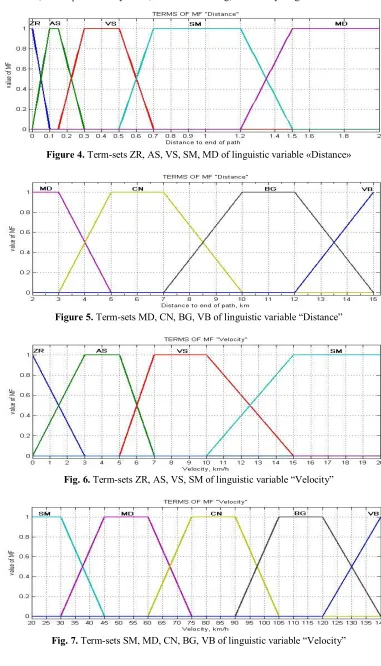
At the stage of fuzzification for clear input values “Dist”, “Vel”, the belonging to separate terms of linguistic variables "Distance", "Velocity", “Reserve of time” are calculated. The membership functions shown in Fig. 4-8 are used for this purpose.
The obtained value of the speed of stabilization ( ) also inputted in the LLM (unit of regulator of time motion), where it used as a fuzzy number “approximately
” with membership function Gaussian:
( , , ) =
( )
.
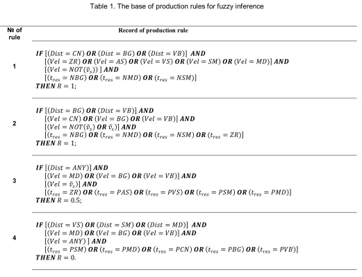
The following steps include: finding the membership functions of the prerequisites of each specific rule for specific input signals; finding the resulting membership functions of each rule and the resulting membership function of the entire set of rules are implemented on the basis of the production rules base presented in table 1. This uses a simplified fuzzy inference scheme in which the right-hand sides of the rules are clearly defined, and the fuzzy inference produces a discrete set of solutions for each element that has a certain degree of confidence. The values of the output variable are selected with maximum confidence.
Thus in fig. 4-7 the following designations are used: ZR - zero, AS – absolute small, VS – very small, SM - small, MD - middle, CN - considerable, BG - big, VB –
R
v
,
u
z
T
v
dist
,
apprv
rest
t
very big, and in fig. 8: NBG – negative big, NMD - negative middle, NSM- negative small, ZR - zero, PAS – positive absolute small, PVS - positive very small, PSM -
positive small, PMD – positive middle, PCN - positive considerable, PBG – positive big, PVB - positive very big; ANY - anything.
Figure 4. Term-sets ZR, AS, VS, SM, MD of linguistic variable «Distance»
Figure 5. Term-sets MD, CN, BG, VB of linguistic variable “Distance”
Fig. 6. Term-sets ZR, AS, VS, SM of linguistic variable “Velocity”
Fig. 7. Term-sets SM, MD, CN, BG, VB of linguistic variable “Velocity”
6
Fig. 8. Term-sets NBG, NMD, NSM, ZR, PAS, PVS, PSM, PMD, PCN, PBG, PVB of linguistic variable “Reserve of time"
Table 1. The base of production rules for fuzzy inference
№ of rule
Record of production rule
1
[( = ) ( = ) ( = )]
[( = ) ( = ) ( = ) ( = ) ( = )]
[( = ( )) ]
[( = ) ( = ) ( = )]
= 1;
2
[( = ) ( = )]
[( = ) ( = ) ( = )]
[( = ( ) )]
[( = ) ( = ) ( = ) ( = )]
= 1;
3
[( = )]
[( = ) ( = ) ( = )]
[( = )]
[( = ) ( = ) ( = ) ( = ) ( = )]
= 0.5;
4
[( = ) ( = ) ( = )]
[( = ) ( = ) ( = )]
[( = ) ]
[( = ) ( = ) ( = ) ( = ) ( = )]
= 0.
These rules define the control in the modes of acceleration, stable speed and coasting. At realization of regenerative and pneumatic braking is carried out the transition to programmed control. In this case the program speed is determined on the basis of the preset deceleration for both modes: = √25920 ∙ ∙ .
4. Computational experiment
Developed on the basis of ratios (1-11) simulation model of train movement (Fig. 3) allows to explore different ways to control the movement of the train. With its help the developed method of management on the basis of
logical-linguistic model was investigated. The computational experiment included two stages:
1 Search for control as a dependence u=u (t) (or u=u (s)). For this purpose, the authors developed a special algorithm of search optimization using a simulation model based on the optimality criteria set out in section 2.1. This method of control can be assigned to the class of optimal programmed control without feedback. This approach can be used in the laboratory during research, as well as in the development of energy-optimal mode maps of train driving. It requires certain computing resources and special software. The result can be used as a "etalon" to assess the effectiveness of control methods designed to be implemented on Board the train in real time.
2 Simulation modeling of train movememt control based on the developed logical-linguistic model. The latter refers to the methods of control with feedback, since the values of the parameters “Dist”, “Vel”, characterizing the state of the control object are used in the development of the control action (R). This method can be relatively easy to implement on Board the train and does not require such computing resources as method 1.
The developed logical-linguistic model was investigated by means of a computational experiment with a simulation model applied to suburban electric trains as well as passenger trains. The results of control using the LLM was compared with the results of programmed control (control without feedback), calculated on the basis of search optimization. As an example, some simulation results are given in table. 2. The structure of optimal trajectories in both cases corresponds to fig. 1.
Table2. Result of simulation
№ parameter value
1 , km 0
2 , km 25
4 , sec 900
5 , ton 1120
6 , km/h 120
Result of control with LLM
8 , km/h 113
9 910
10 A, kWt·h 320
Result of programmed control on-based searching optimization
11 , km/h 115
12 898
13 A, kWt·h 326
If using LLM there is a deviation from the schedule within 15 seconds, which can be considered an acceptable result. It compensated a small reduction in energy consumption. It should also be noted that deviations of
actual parameters from those calculated in real operating conditions more influenced for control quality [3] at the programmed control method than control with LLM.
5. Conclusions
1 By simulation modeling it is established that the quality of control obtained with the help of LLM is somewhat different from the results of programmed control based on search optimization. The implementation of the latter approach in real time is difficult because it requires considerable computing resources. In addition, the quality of control with the help of LLM is less influenced by the deviation of the actual traffic parameters from the calculated ones and the influence of external disturbances, which can be decisive in operation.
2 The proposed logical-linguistic model can be used in the construction of on-board systems of suburban electric trains.
3 It is advisable to continue research for adaptation of the logical-linguistic model for various types of control objects - passenger and freight trains, as well as traffic conditions, which determined by a complex path profile.
References
[1] Conference: K.I. Yurenko (2016) “Optimization of regimes of train operations in onboard control-information system of loco”, Proc. of VII Intern. Sci. Conf. “TRIS-2016”, Taganrog: SfedU, 2016 pp.97-102.
[2] Conference: K.I.Yurenko, A.N. Sapunkov and E.I. Fandeev (2012), “Evolution of rolling-stocks onboard control system”, Proc. of VIII sci.-pract. conf.” The scientific industry of the European continent”, 27 nov. – 5 dec. 2012, vol. 25, Tech. science, Publ. house “Education and Science”, pp.44-49.
[3] Journal article: K.I. Yurenko, A.N. Savos'kin and E.I. Fandeev (2015), “Mathematical modeling of the energy optimum modes of driving the train taking into account perturbation”, University News. Northcaucasian region. Technical Sciences Series, 2015, No. 3, pp. 34-44. [4] Book: G.V. Faminskiy and E.V. Erofeev (1978),
Automatic devices for driving trains, Moscow: Transport, 103 p., 1978.
[5] Book: L.A. Baranov (1990) Microprocessor-based autodriver system of electric rolling stock, Moscow: Transport, 1990, 272 p..
[6] Book: L.A. Baranov, E.V. Erofeev, I.S. Meleshin and L.M. Chin (2011), Optimization of train control, Moscow.: MIIT, 2011, 164 p.
[7] Journal article: L.A. Muginstein, A. E. Ilyutovich and I. A. Yabko (2012), “Energy optimal methods of train control”, col. of sci. papers of VNIIZhT, Moscow: Intext, 2012,80p..
[8] Book: A.V. Klimovich (2008) "Optimization of the control of train movement for minimum energy costs for traction", Moscow: Company Sputnik+, 2008, 263 p..
[9] Book: Y. Wang, B. Ning, F. Cao, B. De Schutter, and T.J.J. van den Boom (2011) “A survey on optimal trajectory planning for train operations,” Proceedings of the 2011 IEEE International Conference on Intelligent Rail
0
s
ks
zT
trainm
maxv
sv
xt
sv
xt
8
Transportation (ICIRT 2011), Beijing, China, July 2011, pp. 589–594.
[10] Journal article: M. Domínguez, A. Fernández, A. P. Cucala and J. Blanquer (2010) “Efficient design of Automatic Train Operation speed profiles with on board energy storage devices”, Computers in Railways XII, WIT Transactions on The Built Environment, WIT Press, vol. 114, 2010, pp. 509-520.
[11] Book: V. E. Rosenfeld, I. P. Isaev, N. N. Sidorov, M. I. Ozerov (1995) “Theory of electric traction”, Moscow: Transport, 1995, 249 p.
[12] Book: S. I. Osipov, S. Osipov, V. P. Feoktistov (2006) “Theory of electric traction”, Moscow: Marshrut, 2006, 436p.
[13] Journal article: Sankar, G., Saravana Kumar, S. (2006) Fuzzy logic based automatic braking system in trains. Power Electronics, 2006. India International Conference on, Chennai, 2006, pp. 383-387. IICPE (2006)
[14] Journal article: Yasunobu, S., Miamoto, S., Ihara, H. (2002) A Fuzzy Control for Train Automatic Stop Control.Trans. of the Society of Instrument and Control Engineers. Vol.E-2, No.1, 1/9 (2002).
[15] Book: Mamun, B. I. R., Jubayer, J., Hafizah, H., Badariah, B. (2011) Subway Train Braking System: A Fuzzy Based Hardware Approach. American Journal of Applied Sciences 8 (7), pp. 740-747 (2011)
[16] Journal article: K. Yurenko (2016) “Automatic Control of Train Brakes with Fuzzy Logic”, Proceedings of the First International Scientific Conference “Intelligent Information Technologies for Industry” (IITI’16), vol. 2, 2016, pp. 345–351.
[17] Book: T.J. Ross (2010) “Fuzzy logic with engineering application”, Third Edition, John Wiley & Sons, 2010, 607p.