SELF-DEPENDABLE EASY NAVIGATION SYSTEM
FOR BLIND PERSONS
Ponnaluru Sowjanya
1, L.Srinivas Reddy
21
M.Tech Scholar (ES),
2Assistant
Professor (DECS),
Nalanda Institute of Engineering & Technology
(NIET) Siddhartha Nagar, Guntur, (India)
ABSTRACT
Now-a-day’s traffic is increasing rapidly. It is very complicated to cross the road or walk on road. It is even complicated for blind people to walk on road etc. Our project found a solution for the blind people. In proposed project blind people can easily detect the obstacles with the help of sensors placed in their coat. With this we can detect object at long range and also it can give time for the blind people to move aside from the object. By pleasing sensors on two sides of the person can detect which side is risky by that we can reduce the risk of accidents. Since blind people can’t see we installed a voice module which can easily warn person by pre-recorded voices. Blind people won’t face any problems in understanding the voices. If object is even close then
vibration is given to person using vibration motor which is installed in our project.
Keywords
:-Obstacle Detection, Ultrasonic Sensor, Micro Controller, Voice Play Back, Vibration
Motor.
I.
INTRODUCTION
In real time applications it is complicated to find the distance using ordinary sensors. To get most accurate value
we are going to use ultrasonic sensor for the detection of the range of the object from the person. Ultrasonic
sensors are fixed to the blind person. From these sensors we are not only obtaining the object detection we are
also getting the range of the object. Ultrasonic sensors are accurate up to 4m range. They are easy to operate and
economic when compared to accuracy. Since ultrasonic sensors are working based on the sound signal the
distance can’t be interrupted by sun rays or sound pollution surrounded. When we give trigger to the ultrasonic
sensor then sensor generates a sound signal and sensor sends the reflected sound signal to micro controller as
echo Pulse. By reading echo signal we can easily determine the range of the obstacle from two sides of person.
It is useful when a vehicle is coming to the person from behind. So that user can be saved.
There are two other ultrasonic sensors placed around the person which are back side/front side or left side/right
side etc, is placed down words facing with some slope like 900. With these all two sensors we can sense all the
objects surrounding persons. As described on above we read the echo signals after giving triggers for two
ultrasonic sensors. After receiving the data from two sensors we can calculate is there any sensor which is
sensing low distance in the sense object is nearby. If there is any object nearby then we can play corresponding
voice in voice module and at the same time we are displaying emergency message by the help of LCD. If object
II.
DESCRIPTION
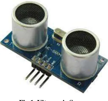
2.1 Ultrasonic Sensors
Ultrasonic sensor is used in real time applications. By using ultrasonic sensor we are not only detecting the
obstacle but also the range for different types to alerts. The basic principle of ultrasonic sensor is transmitting a
high frequency of ultrasonic range which is above than 4 MHz frequency. After transmitting the signal sensor
waits for the reflection signal of same frequency. Whenever Transmitted sound signal is interrupted with the
obstacle an echo signal is reflected from object. We are having another sensor for detecting a received sound
signal. Depending on the time taken for the reflection of the signal an echo signal is generated in electrical
pulses. The generated pulse is directly proportional range of object. After receiving the signal we have to
calculate the range. The calculated range is stored for the corresponding sensor.
The trigger pulse is active high. Pulse must be given more than 10ms. After receiving the 10ms trigger pulse
ultrasonic sensor generates 8 sonic burst signals and transmits them to air. If there is any object in front of the
sensor sound signal is reflected. It does not depend on colour of the object. If sound signal is interrupted with
the black surface there is a chance to observe the sound signal instead of reflection. Since our sensor output does
not depends on how much sound signal is reflected but it depends on how much time it taken. So we don’t have
errors in calculation of range regarding the colour of the object. But we have some kind of errors in the shape of
the object. If the objects have round shape then it can effect calculation of range. In case of round objects less
amount of sound signal received at sensors because reflected sound signal distributes in all direction not only in
the direction of sensor. But at short ranges like less 4 m we can have accurate range values. Since we don’t have
any problems while detecting the range below 4 m we can use ultrasonic sensor in our project because 4 m is
very long range than we require.
Fig 1. Ultrasonic Sensor
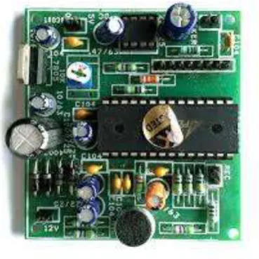
2.2 LPC2148
LPC2148 is upgraded from the microprocessor which is used in real time applications. It is developed from
microprocessor ARM 7. ARM processors are developed by Philips. LPC2148 is 32 bit micro controller.
Important specifications of LPC2148
32 bit registers
64 input/output programmable pins
2 UART buses
2 I2C buses
512 kb of ROM
60 MHz processing speed
Power supply of 3.3v
2.3 Liquid Crystal Display
It consists of 16*2 characters Liquid Crystal Display. Resolution of each character in LCD is 5*7 dot matrix. It
consists of 16 characters in upper line and 16 characters in lower line. We can display total of 32 characters in
LCD. It consists of 8 bit data lines and RS, Enable, R/W for controlling the data. We can communicate with
LCD using 4 bit data line or 8 bit data lines. According to our requirement we can communicate. If we are
having less I/O pins to communicate with LCD then we can use 4-bit communication or else we can use 8-bit
communication.
2.4 Voice Module
Voice module is capable of recording the voices for eight channels. We can record the voices in eight different
channels and play them whenever we wanted to play voice. We can record the five voices for five sides. In case
of voice recording and playing we have a major problem known as noise problem. Voice module consists of
inbuilt amplifier. So we don’t require any external amplifier. We can directly play from head phone speaker to large speaker size of 4W. We don’t need any amplifier externally. Since we have an Integrated circuit it results
in less power consumption and also significant result in reduction of noise. Voice module is compatible of
playing a small speaker like head phone to large speaker like 4W by not using any interface like audio amplifier
etc. This reduces the noises while recording and playing of audio signals.
2.5 Vibrating Motor
Vibrating motor is nothing but a motor which is having unbalanced coupler. Since the coupler is unbalanced
when motor is on it creates continues shake for every object. Vibration is very useful while alerting a person.
We are using vibrating alert in only emergency cases. We are having drawbacks of vibrating alert like heart
attack. So we are using vibrating alert only in emergency to reduce the drawbacks. We are already having voice
alert for alerting user it’s very rare to giving an emergency alert to user. We can see coupler which is connected
to motor pole it looks like semicircle which is known as unbalanced coupler.
Fig 3 Vibrating Motor
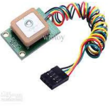
2.6 GPS
In order to track the exact location we use GPS Module. It is arranged at specified baud rate range and can
interface with TTL/CMOS Logic. We can also locate exact time, date and location in predefined manner. The
specified format is based on NMEA message formats like $GPGGA – Identify the time, position and predefined
data. $GPGLL– identifies the latitude, longitude and fixed data, $GPZDA – identify the date and time.
III.
DETECTION
ALGORITHM
3.1 Flow Chart
The above flow chart describes the overall project explanation in simple manner. Based on flow chart we
perform the task in our project.
IV.
PRINCIPLE
OF
THE
DEVICE
Major components used in our project are LPC2148, Voice module, vibrating motor, Ultrasonic sensor and
GPS Module. The main sensor we used is ultrasonic sensor. Inputs of project are Ultrasonic sensor; Outputs of
this project are voice module, vibrating motor, LCD. Vibrating motor is only used in emergency situation only.
We can also track the location through GPS Module and get alertness to user of certain location based on voice
module.
When we give a trigger pulse of 10 msec to the ultrasonic sensor then sensor sends a sonic burst through speaker.
When sensor recessives the reflected signal then it sends an echo signal to the microcontroller. The recived echo
signal time is directly proprotional to its range. We can get exact range by taking a referance distance. After
calculating range for one sensor we will go for another sensor. Same procedure is used for all sensors to
calculate the range. After completion of calcualating from two sides we check for any object near by any sensor.
If no object is detected then we start reading values from all sensor and the process continues.
If there is any obstacle is near by then we alert user through voice message using voice module. Corresponding
voice can be played with grounding the corresponding pin in voice module. If object is very close then we can
alert person by using vibration alert using vibration motor. When we power the motor it automatically generates
vibration that can alert user in emeargency.
We record five different voices in voice module. So that we can play all voices when ever we require. Since we
don’t require any pre amplifiers while recording and post amplifiers while playing voices the noises in voices
are very less when compared to other circuits. So user can understand voices very easily. Even user neglected
voices we have vibration motor which is very useful while alerting the user.
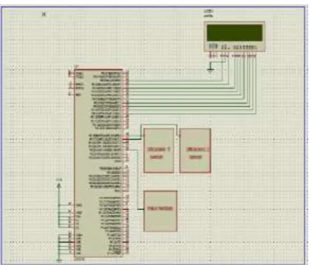
4.2 Schematic Representation
Fig 5.Schematic Representation of Overall Project
When we switch on the project Micro controller sends an Initialization message to LCD and starts triggering and
receiving data from two ultrasonic sensors one by one. When data is received from ultrasonic sensor micro
controller calculated and stored the range from two sides. After storing the range controller sends the ranges of
two sides to LCD. Then controller checks if there is obstacle at short range. When object came near to Micro
controller played corresponding voice with the help of voice module and stopped playing after object is at long
distances. When object came too close then controller played a corresponding voice and alerted user with
V.
CONCLUSION
In this paper we represent a project which is used for the obstacle detection. This project is very useful for the
blind peoples mostly who are living in cities and towns. Since our project consists of voice alert and at the same
time vibrating alert we can reduce the complexities of blind people who are cross reads in high traffic areas.
Since we are using real time sensors, micro controller, voice module the real time errors are significantly
reduced.
REFERENCES
[1] S. M. Metev and V. P. Veiko, Laser Assisted Micro technology, 2nd ed., R. M. Osgood, Jr., Ed. Berlin,
Germany: Springer-Verlag, 1998.
[2] J. Breckling, Ed., The Analysis of Directional Time Series: Applications to Wind Speed and Direction, ser.
Lecture Notes in Statistics. Berlin, Germany: Springer, 1989, vol. 61.
[3] S. Zhang, C. Zhu, J. K. O. Sin, and P. K. T. Mok, “A novel ultrathin elevated channel low-temperature
poly-Si TFT,” IEEE Electron Device Lett., vol. 20, pp. 569–571, Nov. 1999.
[4] M. Wegmuller, J. P. von der Weid, P. Oberson, and N. Gisin, “High resolution fiber distributed
measurements with coherent OFDR,” in Proc. ECOC’00, 2000, paper 11.3.4, p. 109.
[5] R. E. Sorace, V. S. Reinhardt, and S. A. Vaughn, “High-speed digital-to-RF converter,” U.S. Patent 5 668
842, Sept. 16, 1997.
[6] (2002) The IEEE website. [Online]. Available: http://www.ieee.org/
[7] M. Shell. (2002) IEEEtran homepage on CTAN. [Online]. Available:
http://www.ctan.org/tex-archive/macros/latex/contrib/supported/IEEEtran/
[8] FLEXChip Signal Processor (MC68175/D), Motorola, 1996. [9] “PDCA12-70 data sheet,” Opto Speed SA, Mezzovico, Switzerland.
[10] A. Karnik, “Performance of TCP congestion control with rate feedback: TCP/ABR and rate adaptive
TCP/IP,” M. Eng. thesis, Indian Institute of Science, Bangalore, India, Jan. 1999.
[11] J. Padhye, V. Firoiu, and D. Towsley, “A stochastic model of TCP Reno congestion avoidance and
control,” Univ. of Massachusetts, Amherst, MA, CMPSCI Tech. Rep. 99-02, 1999.
[12] Wireless LAN Medium Access Control (MAC) and Physical Layer (PHY) Specification, IEEE Std. 802.11, 1997.
AUTHOR
DETAILS
Ponnaluru Sowjanya, pursuing M.Tech (ES) from Nalanda Institute of Engineering & Technology (NIET) Siddhartha Nagar, Kantepudi (v), Sattenapalli, Guntur-522438.
L. Srinivas Reddy, working as Assistant Professor (DECS) from Nalanda Institute of