IJEDR1701111
International Journal of Engineering Development and Research (www.ijedr.org)702
Optimization of production process of Splitter
Shoe using DMAIC methodology
A case study on Splitter Shoe
1
Nachiket Kulkarni,
2Jogesh Pawar,
3Suyog Pawar,
4Bhavesh Kondhalkar,
5Prof. Kulwant Dhankar
1
Student, 2 Student, 3 Student, 4Student, 5Professor
1
Department of Mechanical Engineering,
1
Lokmanya Tila k College of Eng ineering, Navi Mu mbai,India
________________________________________________________________________________________________________
Abstract—The DMAIC methodology is one of the most used techniques in the Quality Management field. Its benefits come from the improvement of the process by identifying and removing the root causes of defects. It is a disciplined, statistical and scien tific problem solving technique, which uses statistical and non-statistical tools integrated with methodology to identify and eliminate number of defects. This paper provides implementation of DMAIC methodology for optimization of production process of splitter shoe. The purpose of this paper is to present the application of the DMAIC methodology which refers to a data-driven quality strategy for improving processes.
IndexTerms—Optimization, Quality Management, DMAIC, S plitter Shoe
________________________________________________________________________________________________________
I.IN TRO DUC TION
Co mpanies are facing tough challenge to respond to the needs of customer while keep ing manufacturing & other related costs down .Under DMAIC methodology Companies can cut down their costs by reducing the production of defective parts. All ma jor issues related to product, processes are addressed using DMAIC methods.
Statistical Quality Control (SQC), Zero Defects and Total Quality Management (TQM), have been key players in quality management techniques from many years, while DMAIC is one of the more recent productivity improvement initiatives to gain popularity and acceptance in many industries. In providing background information, and giving evidence of the emerging importance of the methodology. These paper tend to explain the features of DMAIC rather than critically appraising or enhanci ng it.
II.LITERA TURE R EVIEW
(1) Hongbo Wang et al: This paper summaries, basic concept, DMAIC, DFSS and deployment.DMAIC is a closed-loop process that aims to identify and eliminate unproductive steps, often focuses on new measurements, and applies technology for continu ous improvement. Then, some sectors that benefit from the imp le mentation of DMAIC methodo logy are listed out, and the key factors influencing the successful project imple mentation are identified. This paper helps the readers to learn how to carry out a small-scale project with process improve ment methodologies, including guidance on the applic ation of tools.
(2) Senapati et al [2004]: has suggested DMAIC approach through deming cycle, TQM, MBNQA, and Dorian shanin’s statistical engineering. He has suggested different methodologies as an improvement in itiative.
(3) Antony et al [2005]: has presented the application of Define-Measure-Analyze-Improve-Control (DMAIC) methodology to reduce engine-overheating problem in an automotive industry. The experimental data collected during DMAIC project will provide a greater scope for the wider application of this methodology across the automobile co mpanies in future.
(4)Ku mar and Sosnoski et al [2009]: has exa mined one of the shop floor chronic quality issue during heat treatment process through DMAIC methodology.
(5) Sahoo et al. [2008]: has imple mented DMAIC in order to optimize rad ial forging operation. The authors had the prime focus on minimizing the residual stresses developed in the components manufactured by radial forging.
III.STEPS INDMAIC
IJEDR1701111
International Journal of Engineering Development and Research (www.ijedr.org)703
Table 1IV.ABOUTPRODUCT
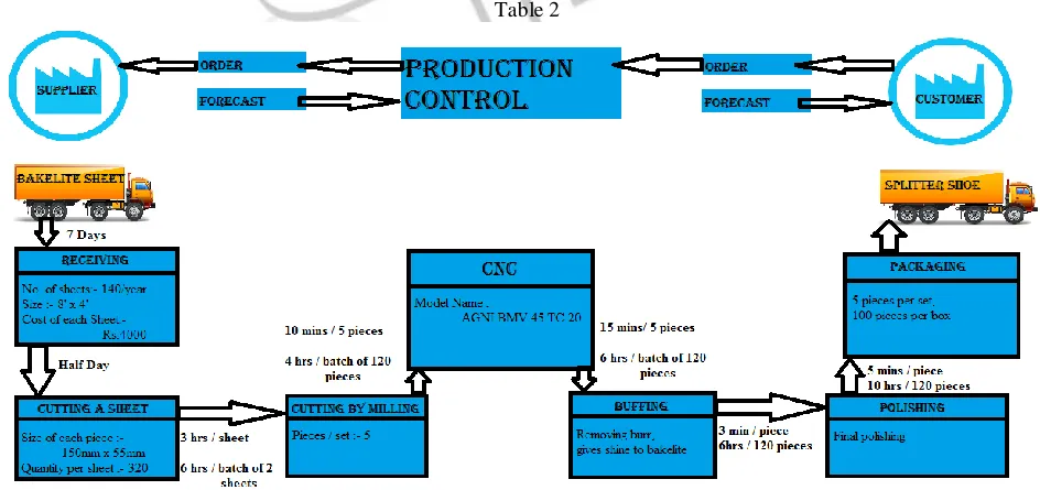
SPLITTER S HOE- It is a product manufactured by the Jupiter Engineering Works that is used for industrial applications such as separating the fibre glass threads from each other while winding them. The production is yearly and the product manufactur ed is in batches of different types according to the order.
The processes done on Splitter Shoe are as follows - 1. Raw materia l- Ba kelite Sheet of size 8 feet * 4 feet. 2. Cutting in pieces of 6 inch * 1 ½ inch by milling operation 3. Sorting in batches by thickness
4. Goes to CNC for cutting internal pattern 5. Buffing for smooth surfaces
6. Polishing for better finishing 7. Quality check
8. Packing and shipping
Types and series of Splitter shoe.
There are 2 ma jor series of Splitter shoe as following
1. S- series: S series of Sp litter shoe consists of smaller and variable types of shoes. 2. P- series: P series consists same size with different no of splits eg. 8P, 6P etc.
The first alphabet of the name of splitter shoe denotes the standard size of the shoe, and the digit after the letter denotes the number of holes in shoe for separating fibre glass.
IJEDR1701111
International Journal of Engineering Development and Research (www.ijedr.org)704
1. RAW MATERIAL US ED- Bake lite Sheet1. Bake lite has a number of important properties. It can be molded very quickly, allowing similar units to be produced on large scale.
2. Moldings are smooth, retain their shape and are resistant to heat, scratches, and destructive solvents. 3. It is also resistant to electricity, and prized for its low conductivity.
4. It is not fle xible.
5. Phenolic resin products may swell slightly under conditions of extre me hu mid ity. When rubbed or burnt, Bakelite has a distinctive, acrid, sickly -sweet or fishy odor.
2. CUTTING OPERATION-
Usually done by circular saw. A circu lar saw is a tool for cutting many materia ls such as wood, plastic, or metal and may be hand-held or mounted to a machine. In woodworking the term "circular saw" refers specifically to the hand -held type and the table saw are other common forms of circular saws. Circular saw blades are specially designed for each particular material they are intended to cut and in cutting material a re specifically designed for making rip-cuts and cross-cuts.
3. MILLING OPERATION:-
Milling is a cutting process that uses a milling cutter to remove materia l fro m the surface of a workp iece. The milling cutter is a rotary cutting tool, often with multip le cutting points. The milling cutter enters the workpiece, the cutting edges of the tool repeatedly cut into and getting off from material shaving off chips off the workpiece. The Milling is a cutting process where a milling cutter is used to remove material fro m surface of a workpiece. The milling cutter is a rotary cutting tool, often with mult iple cutting points. The milling cutter starts cutting the workpiece, the cutting edges of the tool repeatedly cut into and exit fro m the material, shaving off chips from the workpiece with each pass. The cutting action is shear deformation; materia l is pushed off the workpiece in t iny clumps. He re, 8 pieces of dimensions 110x12.5 (sma lle r) PRIMARY SPLITTER SHOEOR 152x38 (larger) SECONDARY SPLITTER SHOE. Drill is also done of 4.2 mm diameter at 10mm fro m each end.
4. CNC MACHINING:-
CNC Machining is a process used in the manufacturing sector that involves the use of computers to control machine tools. Under CNC Machining, machine tools function through numerical control. A computer program is customized for an object and the machines are programmed with CNC machining language that controls all features like feed rate, coordination and speeds. With CNC machining, the computer can control exact velocity and positioning. CNC mach ining is used in manufacturing both metal and plastic parts. The model used in the industry is AGNI BM V 45 TC 20 and the control board of the CNC is by SIEM ENS.
5. SOFTWARES US ED FOR DES IGNING:-
DELCAM:- DELCAM is a supplier of advanced CAD/CAM software for the manufacturing industry. It is a global developer of product design and manufacturing software. It now operates as a wholly owned, independently operated subsidiary of Autodesk.
In Jupiter engineering works DELCAM is used for comple x 3d designs only.
MASTERCAM:- CNC Soft ware is one of the oldest developers of computer based software. Master cam, CNC Softwa re’s ma in product, started as a 2D CAM system with CAD tools that let machinists design 3D parts on a computer screen and also guided computer numerical controlled (CNC) machine tools in the manufacture of parts. Since then, Master cam has grown into the most widely used CAD/CAM package in the world for CNC machines. Here, in Jupiter engineering works MASTERCAM is used for 2d or 3d designs.
6. CHAMFERING AND POLIS HING:-
CHAMFERING- A chamfer is a trans itional edge between two faces of an object. It can also be known as a bevel but connotes more often cutting and is forty five with respect to the two adjoining faces.
IJEDR1701111
International Journal of Engineering Development and Research (www.ijedr.org)705
7. B UFFING:-For most, buffing means the use of a tool to correct and shine the surface of a metallic device or machined part. The tool used can vary from rotary buffers to orbital buffers. Buffing is often used in conjunction with a type of compound used to smooth the surface of material. These are fine abrasives added to greases to create rectangular solid sticks or fluids. A number of buffing methods exist. There is cut buffing which involves cutting down the surface of brass, copper, and other metals and coloring it at the same time . Ne xt there is color buffing. This process involves using polishes or buffing compounds to give a mirror-like smooth shine. Colour buffing is usually done once the surface of have become suffic iently smooth.
VI.IMPLEMENTINGDMAIC
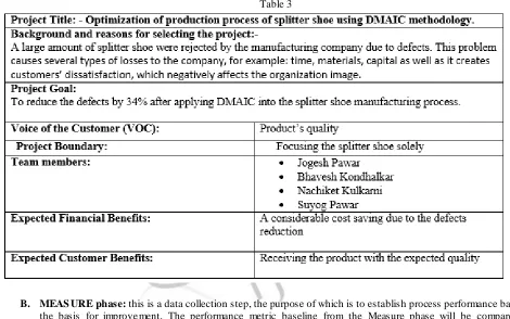
A. DEFINE Phase: In order to imp le ment the DMAIC Methodology it is crucial to define the process as well as problem associated with it The purpose of this step is to clearly articulate the goal, business problem, potential resources, and high level project timeline. This information is captured within project charter document. Define the following: A critical proble m
What are the critical process outputs?
The project boundaries – Where does the process begin and end?
The process to be improved
The details of define phase are as follows -
Table 3
B. MEAS URE phase: this is a data collection step, the purpose of which is to establish process performance baselines as the basis for improve ment. The performance metric baseline from the Measure phase will be compare d to the performance metric at the conclusion of the project to determine whether significant improvement has been made. It involves;
Develop a plan for the collection of data for the process Gather data to identify types of defects
IJEDR1701111
International Journal of Engineering Development and Research (www.ijedr.org)706
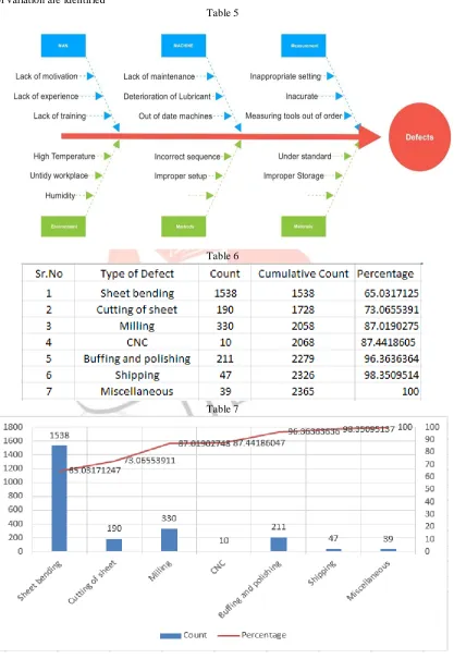
causes of errors. A large number of potential root causes of the project problem are identified via root cause analysis. The root causes were identified using several tools. This process is repeated until "valid" root causes can be identified. it involves; Identify how the process inputs affect the process outputs. Data are ana lyzed to understand the magnitude of contribution of each root cause, Statistical data tested using p-values with Pareto charts, bar graph, Histograms, and line plots are often used to do this.
Opportunities for imp rovements are priorit ized Sources of variation are identified
Table 5
Table 6
IJEDR1701111
International Journal of Engineering Development and Research (www.ijedr.org)707
D. IMPROVE Phase: This step is recommended to identify, test and imp le ment a solution to the problem, in part or inwhole project. This depends on the situation. Identify creative solutions to eliminate the key root causes for fixing and preventing process problems. The purpose of this step can also be to find solutions without imple ment ing them it involves;
Create
Focus on the simplest and easiest solutions
Create a p lan to imp rove
Imple ment it
Using the data from the imp le mentation of the above it is now possible to improve the process by designing easy and unique solutions to fix and prevent problems. This is achieved by using technology to build innovative solutions to Develop and imp le ment a plan.
We identified the cause of defects in splitter shoe which causes 80 % of proble m.
The improve ments suggested to the company are 1) Reducing size of the sheet to 4 feet*4 feet 2) Use of better fixtures with guid ing scale
E. CONTROL Phase: The purpose of this step is to monitor the improve ments to ensure continued and sustainable success. Create a control plan. Upgrade business documents and training records as required. A Control chart is useful while the Control stage. It assist is the stability of the improvements over time by serving as a guide to continue over viewing the process.
Control and sustain improve ments over time by –
Developing, documenting and imp le menting upgrading plan
Integrating the improve ments throughout the company through the use of training, staffing and incentives. Control phase should be conducted by company after the changes were applied.
VII. RES ULT: By 20-80 cause and defect principle, eliminating top 20% causes that produce 80% o f defects. 1) As all bending defects cannot be eliminated, assuming 75% of the bending defects are eliminated.
i.e. actual defects due to bending= 1538,
De fects after reducing ra w materia l sheet size= 1538-(1538* 0.75) =385
2) Incorrect cutting of sheet can be eliminated totally hence eliminating defects due to that Hence defects due to incorrect cutting = 0
Therefore total defects after elimination = 1022 As the defects reduced from 14.59% to 6.3% Hence defects reduced by = 56.78%
Hence the incre ment in sig ma leve l is achieved.
VIII. CONCLUS ION: .Based on this methodology, further research can be accomplished in manufacturing company. This paper gives incisive insight into the existing method of manufacturing splitter shoe. Basically DMAIC methodology is beneficia l both for manufacturing or service concerns and Large or smal l scale organizat ions. It is more essential to learn how to enhance the productivity and improve its imp le mentation issues for the growing number o f firms o r organizations that are choosing to adopt it with the aim of p rocess improve ment. The prima ry focus was on improving overall o rganizat ional performance, not just pinpointing and counting defects.
REFER ENC ES
[1] Senapati, N.R. Six sig ma : myths and realit ies. International Journal of Quality & Reliability Management, (2004). 21(6). [2] Antony, J., Ku mar, M., Tiwari, M.K. An application of Six Sig ma methodology to reduce engine - overheating problem in an automotive company, Proceedings of the Institution of Mechanical Engineers, Part b: Journal of Engineering Manufacture August (2005). 1, 219: 633-646.
[3] Ku mar, S., Sosnoski, M. Using DMAIC Six sig ma to systematically imp rove shop floor production quality and costs. International Journal of Productivity and Performance Management, (2009). 58(3).
[4] Sahoo A.K., Tiwari, M.K., M ileha m, A.R. Six Sig ma based approach to optimize rad ial forging operation variab les. Journal of Materials Processing Technology, (2008). 202(1-3)125-136.
[5] Depart ment of Industrial Engineering University of Perugia, Via Duranti 17, Perugia, ITA LY
[6] Virender Narula Research scholar - Mechanical Engineering. Sandeep GroverProfessor & Dean - Engineering & Technology Y M C A University of Sc ience and Technology Faridabad, INDIA