R E S E A R C H
Open Access
Optical character recognition on
heterogeneous SoC for HD automatic
number plate recognition system
Ali Farhat
1*, Omar Hommos
1, Ali Al-Zawqari
1, Abdulhadi Al-Qahtani
1, Faycal Bensaali
1, Abbes Amira
1and Xiaojun Zhai
2Abstract
Automatic number plate recognition (ANPR) systems are becoming vital for safety and security purposes. Typical ANPR systems are based on three stages: number plate localization (NPL), character segmentation (CS), and optical character recognition (OCR). Recently, high definition (HD) cameras have been used to improve their recognition rates. In this paper, four algorithms are proposed for the OCR stage of a real-time HD ANPR system. The proposed algorithms are based on feature extraction (vector crossing, zoning, combined zoning, and vector crossing) and template matching techniques. All proposed algorithms have been implemented using MATLAB as a proof of concept and the best one has been selected for hardware implementation using a heterogeneous system on chip (SoC) platform. The selected platform is the Xilinx Zynq-7000 All Programmable SoC, which consists of an ARM processor and programmable logic. Obtained hardware implementation results have shown that the proposed system can recognize one character in 0.63 ms, with an accuracy of 99.5% while utilizing around 6% of the programmable logic resources. In addition, the use of the heterogenous SoC consumes 36 W which is equivalent to saving around 80% of the energy consumed by the PC used in this work, whereas it is smaller in size by 95%.
Keywords:Optical character recognition, Automatic number plate recognition systems, FPGA, High-level synthesis, Vivado
1 Introduction
Modern cities are implementing intelligent transportation systems (ITSs) as they are an essential part of the infra-structure especially with the increase of population and number of vehicles. The system that identifies vehicles by recognizing their number plates (NPs) is known as an automatic number plate recognition (ANPR) system and it is a part of ITS. It does not require any pre-installed equipment in the vehicle. They are used for several pur-poses including car park management, law enforcement, counter-terrorism and security, tolling, traffic monitoring,
vehicles tracing, and cloning prevention [1–4]. Car cloning
is a car identity theft that is achieved using a false NP. Typically, an ANPR system consists of three stages: number plate localization (NPL), character segmentation (CS), and optical character recognition (OCR). The NPL
stage localizes the vehicle’s NP in an input image. The
CS stage segments the characters of the plate from the localized NP. The OCR stage encodes the segmented
characters to text, which corresponds to the vehicle’s
NP. Therefore, the OCR process is critical as identify-ing one character mistakenly results in wrong vehicle
identification [5,6].
Since old ANPR systems were implemented using powerful computers that had power, size, and cost issues, researchers are motivated to develop new systems that are compact in size, cheaper, and power efficient through utilizing improved algorithms that require less resources [7]. Moreover, new systems target processing high definition (HD) images instead of standard definition (SD) images. The reason is that HD images improve the recognition rate of the ANPR system and increase the area covered by a single camera. Thus, HD cameras could cover multiple lanes instead of dedicating an SD camera for each lane, which reduces the cost. Nevertheless, using HD images requires more time to process one image since HD images have more pixels than SD images. In fact, this * Correspondence:[email protected]
1College of Engineering, Qatar University, Doha, Qatar
Full list of author information is available at the end of the article
introduces a challenge for designers and engineers to achieve real-time processing [8]. However, researchers were able to overcome this impediment through imple-menting their systems using field programmable gate array (FPGA), digital signal processor (DSP), or heterogeneous system on chip (SoC). Heterogeneous SoC consists of two or more processing units that have different architectures such as an FPGA and a DSP.
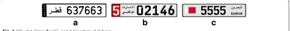
In this paper, the aim is to develop and implement the OCR stage for a real-time HD ANPR system. The system should be implemented on a SoC platform that allows the processing unit to be placed within a HD ANPR camera housing. Moreover, the proposed system will process NPs that consists of numeral characters only. Qatar, United Arab Emirates, and Kingdom of Bahrain are some of the countries that have single font numeral characters NPs as
shown in Fig.1. The proposed system will process HD car
images of resolution 960 × 720 in real-time. In other words, each frame will be processed in less than 40 ms which is equivalent to 25 frame/s. The selected algorithms to implement this stage are based on the fact that the NPs consists of numeral digits only. Four algorithms are devel-oped based on feature extraction and template matching techniques. The four algorithms have been implemented using MATLAB as a proof of concept and the best algorithm, in terms of execution time, and recognition rate has been implemented on a heterogeneous SoC plat-form. The selected platform is the Xilinx Zynq-7000 All Programmable SoC, which is a heterogeneous platform consisting of two processing units: a programmable logic (PL), which is basically an FPGA, and a processing system (PS), the ARM Cortex-A9. The three stages of the devel-oped HD ANPR system should be implemented using one chip only; thus, it is critical to optimize the hardware implementation to achieve an optimum recognition rate while meeting real-time processing.
The remaining sections of this paper are organized as
follows: Section2presents the related work. The proposed
methodologies and algorithms are reported in Section3.
The software implementation is described in Section 4.
Section5discusses the hardware implementation. Results
and discussion are reported in Section 6 and Section 7
concludes the paper.
2 Related work
OCR algorithms are important and widely used to translate the content of scanned images into encoded text. Their
usage ranges from tasks involving translating hand writing on notebooks, parcels, and checks to simpler character recognition tasks since the text in the captured image has a uniform font and was taken under good lighting condi-tions. For ANPR systems, character recognition is relatively less complex because fonts are usually uniform and NPs in some countries include only numeral characters. However, a challenge lies in dealing with the different conditions of these NPs, such as being under sunlight or shadow, dirty, rotated, or having damaged paint [9]. Good OCR algo-rithms must be able to handle these conditions efficiently. Furthermore, as NPs contain a string of several characters, one mistake is enough to wrongly render the detected plate. Thus, the performance of the full ANPR system is affected by this stage performance. In general, OCR algorithms fall into four categories: feature extraction
techniques [10–12], template matching or correlation
[13], statistical classifiers [13–16], and artificial neural
networks (ANN) [5,17]. The performance of the hardware
implementations of a given algorithm differs by its ability to be pipelined and parallelized, and by the amount and type of calculations performed by these parallel blocks.
In [10], different OCR techniques are explained. Zoning, moments, crossings and distances, n-tuples, and charac-teristic loci are techniques that fall into feature extraction. Zoning is about dividing the image into zones and finding the densities of each zone. For example, images were divided into 50 zones such as in [11] where the density of each zone is calculated. Statistical analysis is then used to identify each character. In [12], an OCR algorithm to recognize Persian digits was developed on hardware using the Altera Stratix FPGA. The algorithm extracts specific features like the number of zeros in the horizontal and vertical projections, total number of black pixels in the image, and the top left quarter of the image. Calculated features are then matched to pre-defined features to deter-mine the character. The algorithm was tested using 100 samples that are typed using Microsoft Word and then scanned by a 300 dpi scanner. Testing results have shown that the samples were successfully identified. The proposed OCR algorithm takes 47 ns to process one character. How-ever, in case the noise affected more than two pixels, recog-nition errors start to appear. Subsequently, this proposed algorithm might be useful for OCR systems that process documents, but it is not good enough to be used in an ANPR system where the algorithm should be robust to noise which usually affects the characters as shown later.
In [13], two methods were used to perform OCR. The first uses template matching where it correlates the image of the unknown character with a given set of tem-plates to identify the character. The second one depends on support vector machine (SVM) classifiers that were trained by using feature extraction techniques to identify the input character. In [14], SVMs were used for character classification. Segmented characters from the previous stage were resized to a common size. The feature vectors consist of direct pixel values. A combination of OneVsAll SVMs and Tree-like structure classifiers were used. This was implemented on a TI C64 fixed-point DSP platform that classified one character in 2.88 ms, with a recognition rate of 94%. The proposed OCR stage in [15] is based on a simple nearest neighbor classifier.
The work in [16] proposed a majority voting system based on fuzzy logic to perform OCR. The idea is to implement parallel classifiers to recognize the characters. Then, based on the number of classifiers agreeing on the recognized character in the image, three scenarios are used to determine the final result of the OCR stage. The fuzzy logic plays a critical role in deciding which scenario to use while recognizing every character based on four fuzzy variables: distortion, resolution, angle, and contrast. These variables are used because they influence the performance of the classifiers.
In [5], an algorithm for the OCR stage of an ANPR system was developed and implemented for the UK NPs. The 4M Gates Xilinx Virtex-4 LX40 was chosen as the hardware development platform. The algorithm depends on an ANN with 50 neurons to recognize binarized segmented characters. The network was trained using the scaled conjugate gradient algorithm. The overall stage recognition rate was found to be 97.3% and it pro-cesses one character in 0.7 ms. Testing was performed on 3570 characters, which are the output of the previous stages of the system. In [17], self-organizing map (SOM) neural network was used. The employed SOM has an input layer and a computation layer. The design was imple-mented on hardware using the Xilinx Virtex IV FPGA. The hardware design calculates the hamming distance between the weight matrix of each neuron and the input image and uses that to make a decision on the output character. This method was tested using 8531 characters and had a recog-nition rate of 90.93%.
3 Proposed methodologies and algorithms
As mentioned earlier, a typical ANPR system consists of three stages. The first stage is the HD NPL and its proposed implementation by the authors consists of three main oper-ations: image resizing, morphological operations, and con-nected component analysis (CCA). The three operations have been implemented on the PS and PL units to reduce the processing time and take advantage of the pipelining in
the PL. The bilinear image resizing method, and the morphological operations are implemented using the PL, whereas the CCA is executed using the PS. For the second stage proposed implementation, the CS, there are three operations: adaptive thresholding, morphological opera-tions, and CCA. Similar to the HD NPL, the adaptive thresholding and morphological operations has been implemented using the PL, whereas the CCA is executed by the PS. For both stages, the open source computer vision (OpenCV) library is used to perform the CCA. Moreover, the segmented characters by the CS stage are resized using the PS before identifying the characters in the OCR stage. The MATLAB implementation to process one plate using the proposed HD NPL and CS takes 32.84 and 16.4 ms respectively. However, after exploiting the parallelism in the selected hardware platform, the times dropped to 16.17 and 0.59 ms respectively. The recogni-tion rates for the HD NPL is 98% where the CS achieved 98.7%. The two stages utilize around 12% of the available resources in the selected platform. More details about the proposed HD NLP and CS stages by the authors can be
found in [18,19].
OCR could be achieved through different algorithms. The most suitable algorithm is selected based on the application requirements and constraints. For this appli-cation, a Qatari NP contains three to six characters where the characters might be repeated in one plate.
The characters are the digits from‘0’to‘9’and the ideal
characters are shown in Fig.2. In addition, the algorithm
for the OCR stage should be able to recognize the
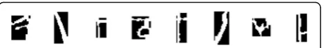
segments that contain‘noise’instead of characters. These
‘noise’ segments are due scratches, dust or plate’s edges
where they might have similar area and ratio
characteris-tics of a character. Figure 3 shows examples of ‘noise’
segments passed by the CS stage of the real-time HD ANPR system as characters.
As noticed in Fig.2, processed images by the stage are
binary where the pixels are represented by either‘1’or‘0.’
In this case, characters and background are represented
using‘1’(white) and‘0’(black) respectively.
The four proposed algorithms have a preprocessing stage. For the first three algorithms, the preprocessing stage resizes the input binary image of the segmented character to 22 × 34 pixels and then adds a border to the image. This size is selected based on the experimental results in [5]. It was found that the larger the size of the segmented characters, the higher the recognition rate of the algorithm while its complexity increases to process
the additional pixels. Therefore, this selected segmented character size was found to be the optimal size that compromises between recognition rate and calculations complexity. The border is required to limit noise effect on the edges of characters and improve zoning feature extraction results. Furthermore, it eases the process for
vector crossing feature extraction. Figure 4a shows the
preprocessing stage for feature extraction-based algorithms. On the other hand, the preprocessing stage for the last algorithm only resizes the image. The advantage of the template matching algorithm is that it depends on the general shape of the character, which does not need a border since the noise minimally affects the algorithm.
Figure4bshows the preprocessing stage for the template
matching-based algorithm. It is worth noting that the bilinear image resizing method is used to resize the images in the whole ANPR system when any image is resized.
To develop and test the algorithms, two sets of HD images are used. The first set of HD images are collected using smart phones. However, the second set consists of 454 HD images and they are taken from the security department at Qatar University. The images are taken by the installed cameras at the gates of the university during different timings, under various lighting and
weather conditions as shown in Fig. 5a, b. Therefore,
the results of the testing for the developed algorithms are more authentic. The HD images of the two sets are processed by the MATLAB implementation of the pro-posed algorithms (HD NPL and CS) of the real-time HD ANPR system to extract the characters. The former char-acter set is used for training purposes and it contained 1242 characters. The latter set is used to test the proposed
algorithms and it consists of 2790 characters. Examples
from the 2790 character set are shown in Fig.5c.
3.1 Vector crossing
The idea of vector crossing is very simple since it only counts the number of times a vector crosses the segmented character in the image. OCR is performed through count-ing the number of times the vector crosses the character. However, to have an effective result, the position of the vectors used should be selected carefully to distinguish between the characters. In addition, increasing the number of used vectors to identify the characters decreases the speed of the algorithm. Therefore, the number of vectors used should be selected wisely. To process the image of a segmented character, the image is preprocessed as shown
in Fig. 4a. As mentioned earlier, the resizing step of the
image is accomplished to have fixed positions for the used vectors to identify the characters. The crossing process
counts the times pixels’color changes from black to white
for two consecutive white pixels. In other words, every black pixel followed by at least two white pixels is counted. Therefore, the border in this case ease the process of vector crossing.
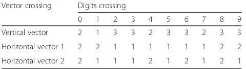
To implement this process, three vectors—one vertical
and two horizontal—are used to cross every image. The
positions of the horizontal vectors are one-third and two-thirds the height of the image. However, the position of the vertical vector is the center of the width. Acquired
results are summarized in Table1.
Hence, by using three vectors, the characters are classified into 8 groups, and only group 311 requires extra processing to identify the character. This is achieved through zoning feature extraction technique which divides the image into zones. The technique is explained in more details in the following subsection. On the other hand, the disadvantage of this algorithm is that it is unable to
iden-tify the images that contain ‘noise’instead of characters.
Therefore, to enhance ‘noise’ recognition, it is assumed
Fig. 3‘Noise’segments passed to the OCR stage as characters
Resizing the character
22 x 34
Add a border
Resizing the character
22 x 34
a
b
Fig. 4The two preprocessing stages for the proposed OCR algorithms.aFeature extraction-based algorithms.bTemplate matching-based algorithm
that every image contains‘noise’ unless it satisfies one of
the characters’conditions. Algorithm 1 shows the pseudo
code of the vector crossing algorithm.
3.2 Zoning
Zoning is another feature extraction technique that is based on dividing the image into zones and then calcu-late the density of white or black pixels in each zone. The number of zones for this application is selected to
be four. Figure 6 shows how an image is divided into
four different zones where each zone has 187 pixels for the selected resolution. Afterwards, the calculated dens-ities of the four zones are matched with the densdens-ities of the reference characters using the absolute difference. After calculating the absolute difference for each zone per reference character, the differences for the four zones per reference character is added to identify the character. The reference character that has the smallest summation is the character in the input image. For the
reference characters’images, it was tested to be the ideal
characters and some of the characters obtained from the training set. The overall results obtained for the two cases were almost identical.
Table 2 shows the densities of each zone for the ideal
resized bordered characters. The density is the total number of white pixels in each zone since the character is represented by the white color in the binary image.
After testing the algorithm using the training set, it was
found that characters ‘5’ and ‘6’ have similar densities.
Hence, many times character ‘5’is identified as character
‘6’due to the effect of noise on the segmented character.
Accordingly, one horizontal vector crossing is used at two-thirds the height of the image to resolve this issue.
The vector would cross character‘5’once where character
‘6’ should be crossed twice. In addition, to reduce the
effect of noise on character‘5,’a small deviation for zoning
was added for character ‘5’ only. This deviation value is
found through testing using the training set to be 60
pixels. Consequently, to identify a character as ‘6,’ the
summation for zoning of character ‘6’ must be the
smallest summation and the value for the crossing
should be 2. However, to identify the character as ‘5,’
there are two possibilities. The first is that the summation
for zoning of character‘5’must be the smallest summation.
The second possibility is when the summation for zoning
of character ‘5’ is within 60 pixels from the smallest
summation and the horizontal crossing equals 1.
Furthermore, a threshold is added to identify ‘noise’
segments. The threshold is set at 100 which zoning smallest summation should not exceed. This value is found through testing. In addition, any image is assumed
to contain‘noise’unless it satisfies a condition for one of
the characters. This improves the recognition rate for the
‘noise’segments. Algorithm 2 shows the pseudo code of the
zoning algorithm. The HOR, VER, and MIN abbreviations stand for horizontal, vertical, and minimum respectively.
3.3 Zoning and vector crossing
The main idea of this algorithm is to combine the previous two techniques to identify the characters. For example, the density of the image and at least one vector crossing are considered when the segmented character is identified. The advantage of this method is that if one method fails in recognizing the character correctly, the other might suc-ceed which increases the probability of correct character recognition and enhance the overall performance. To implement this algorithm, two approaches are followed. The first approach is based on specific conditions selected Table 1Vector crossing using three vectors
Vector crossing Digits crossing
0 1 2 3 4 5 6 7 8 9
Vertical vector 2 1 3 3 2 3 3 2 3 3
Horizontal vector 1 2 2 1 1 1 1 1 1 2 2
Horizontal vector 2 2 1 1 1 2 1 2 1 2 1
Zone 1
Zone 3
Zone 2
Zone 4
Fig. 6The zones of each image
Table 2Zone densities for ideal resized bordered characters
Zone Densities of the digits
0 1 2 3 4 5 6 7 8 9
Zone 1 96 74 56 55 46 135 117 73 106 99
Zone 2 94 177 101 108 30 64 78 104 113 101
Zone 3 95 0 100 62 84 66 96 69 109 83
based on testing using the training set to identify the char-acters. In this approach, the selected vector to identify a character varies from one character to another, and the vector is selected based on how it is affected by noise, rota-tion or any other effects. Moreover, sometimes zoning fail to recognize the character due to noise effect; hence, a marginal value is found practically for zoning to deviate
from for that character (similar to character‘5’in proposed
zoning algorithm). However, in this case, two vectors are used to identify the character. Algorithm 3 summarizes the pseudo code for this approach. Since the two techniques
used in this approach cannot recognize ‘noise’segments
effectively as shown in the first two algorithms, the
assumption that all segments are‘noise’segments unless it
satisfies a condition for a character improves the
recogni-tion rate for‘noise’segments.
On the other hand, the second approach uses the two fea-tures extracted from the input image and a OnevsAll SVM classifier to identify the character. The main aim of using the SVM classifier is to replace the conditions used in algo-rithm 3. The SVM classifier is trained using the training set.
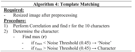
3.4 Template matching
The idea of this algorithm is to match the segmented character with templates of the ten characters and find matching percentages to identify the character. The match-ing process is performed through image correlation where two images are correlated to find the normalized correlation coefficient. Equation (1) represents the mathematical
ex-pression used to correlate the two imagesAandB, whereas
Anmcorresponds to the pixel at rown, columnmin image
AandArepresent the mean of the image. As the matching
between the two images increases, the normalized correl-ation coefficient approaches 1. If the matching decreases or there is no matching, the coefficient drops. Therefore, if the
image contains‘noise’instead of a character, the correlation
coefficient drops for all template characters, which indicates
that the image contains‘noise.’ The threshold that is used
for‘noise’detection is determined by testing to be 0.45. If
this value increases, characters recognition rate drops while
‘noise’ detection improves. However, since the number of
images that contain characters is much greater than‘noise,’
the overall recognition rate will drop. This threshold achieves the best overall recognition rate where the
algorithm is capable of detecting‘noise’segments efficiently
compared to the other algorithms.
r¼
P
mPnAnm−ABnm−B
ffiffiffiffiffiffiffiffiffiffiffiffiffiffiffiffiffiffiffiffiffiffiffiffiffiffiffiffiffiffiffiffiffiffiffiffiffiffiffiffiffiffiffiffiffiffiffiffiffiffiffiffiffiffiffiffiffiffiffiffiffiffiffiffiffiffiffiffiffiffiffiffiffiffiffiffiffiffiffiffiffiffiffiffiffiP
mPnAnm−A2
PmPnBnm−B2
r ð1Þ
The algorithm for template matching correlates the resized segmented character with the ten template images and finds ten correlation coefficients. Afterwards, by
identifying the highest correlation coefficient, the character is identified since the coefficient indicates for the highest matching. The images for the template characters are the
resized ideal characters except for characters‘6’and‘8.’For
these two characters, the template image is selected to be one of the images from the training set as this improved the recognition of the algorithm. The reason for this is that
most of the acquired ‘6’ and ‘8’ characters from the
4 Software implementation
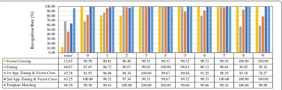
The four proposed algorithms have been implemented using MATLAB and tested using the testing set. The
acquired results for each algorithm are reported in Table3
and Fig.7. The table includes overall recognition rate and
processing time per character where the figure illustrates the recognition rate per character. It is worth noting that the used computer is equipped with an Intel Core i7 4770s 3.1 GHz processor and 8 GB of RAM.
As stated in Table3, the second approach of the
com-bined zoning and vector crossing-based algorithm takes the longest time to process one character since it is the most complicated one. It processes one character in 9.15 ms where the second longest time to process a character is found for the template matching algorithm at 1.95 ms. Both vector crossing and zoning algorithms take 1.33 ms to process one character, whereas the first approach for the combined zoning and vector crossing algorithm takes 1.46 ms. Despite that the vector crossing algorithm is the simplest algorithm, its MATLAB imple-mentation processing time is very close and even equal to the processing time of other algorithms. This might be due to several reasons including the fact that the vector crossing algorithm is not based on matrix operations while
other algorithms’ implementations are based on matrix
operations. Therefore, the processing time for the vector
crossing algorithm is close to the other algorithms’
pro-cessing time as MATLAB is optimized to execute matrices operation.
As shown in the table, the best algorithm that compro-mises between recognition rate and processing time is the template matching algorithm. Therefore, it is selected to implement the OCR stage. Moreover, since a Qatari NP
consists of three to six characters, it will take 5.35–11.7 ms
to be processed by the selected algorithm. This time is ap-proximately one-fourth the time required to achieve real-time processing where the system processes one frame in less than 40 ms (25 frames/s). However, since the first two stages take relatively most of the time in the ANPR system, it is required to improve the processing time of this stage.
Furthermore, by observing Fig. 7, it is clear that the
first three algorithms (vector crossing, zoning and com-bined zoning and vector crossing) do not achieve a good
recognition rate for ‘noise.’ Vector crossing is the worst
at around 12% while zoning achieved better recognition at approximately 68%. In fact, the low rate was anticipated,
as these algorithms lack the ability to identify the ‘noise.’
Conversely, the template matching-based algorithm
out-performs the three algorithms in identifying‘noise’as it
reaches slightly more than 96%. Additionally, the two algorithms that achieved steady recognition rate for characters are the second approach for the combined zoning and vector crossing and the template matching. Indeed, the steady performance in character recognition for these two algorithms yield a high overall recognition rate at 97.13 and 99.5% respectively. However, the recogni-tion rates per character for the other algorithms fluctuates between 12.65 and 100%. Therefore, the overall recogni-tion rates for the vector crossing, the zoning, and the first approach for the combined zoning and vector crossing are around 90, 85, and 90% respectively. Since zoning algorithm is the one that is mostly affected by noise, it was anticipated that zoning algorithm has the lowest overall recognition rate. However, the unexpected result was found when both the vector crossing and the combined zoning and vector crossing first approach algorithms achieved the exact same recognition rate as shown in the table. This in fact does not have any real meaning except that the total number of unrecognized characters out of the 2790 is the same for both algorithms. These unrecognized characters are different as proven by the characters recogni-tion rate in the figure. It is worth noting that while testing the template matching-based algorithm it was found to be capable of recognizing slightly rotated characters without the need for a stage to process rotated NP. This advantage simplifies the design of the real-time HD ANPR system because it eliminates the need for such stage.
Table 3Performance of proposed OCR algorithms based on software implementation—MATLAB
OCR technique Platform Recognition rate (%) Processing time per character (ms)
Vector crossing Intel Core i7 4770s–3.1 GHz
8 GB of RAM
90.43 1.33
Zoning 85.27 1.33
1st approach zoning and vector crossing 90.43 1.46
2nd approach zoning and vector crossing 97.13 9.15
5 Hardware implementation
After proposing and implementing four algorithms using MATLAB, the algorithm with the highest recognition rate is selected for hardware implementation. In addition, since the CS stage of the real-time HD ANPR system segments the characters of the NP and prepare them for identification, the preprocessing stage is moved from the OCR stage to the CS stage.
The Zynq-7000 All programmable SoC heterogeneous platform is selected to implement the whole real-time HD ANPR system. The platform consists of two processing units; the former is a software programmable dual core ARM Cortex-A9 processor (PS), where the latter is a hardware programmable FPGA (PL). Since the platform consists of two separate processing units, the PL could be used to perform and execute computationally intensive tasks that exploits the parallelism of the unit; meanwhile, the PS is utilized to perform and implement other tasks [20]. Several systems synthesize soft core on the FPGA to perform some tasks that requires flexibility or communi-cation with peripherals. The disadvantage of soft cores is that it has lower performance in comparison with hard cores [21], as it runs on lower frequencies.
Since the hardware platform consists of two units, it is essential to know which one to use for the OCR stage implementation. Thus, the stage is implemented using both units and to investigate which one executes the stage faster and observe if it affects the recognition rate of the stage.
5.1 PS implementation
The implementation of the OCR stage using the PS unit is accomplished using the OpenCV library. The bare-metal implementation is not considered as an option since the first two stages of the ANPR system (HD NPL and CS) uses the OpenCV library as mentioned earlier. The library is developed to perform optimized real-time
image processing. To use the library on the PS, it is essential to have an operating system (OS) running on the PS since the library requires system functionality and high level operations [22]. Consequently, the Linaro OS is used because it is specifically developed and highly optimized for ARM and heterogeneous hardware platform architectures [23]. In this case, the OpenCV function calculates the correlation coefficient based on the standard IEEE floating-point single precession data type variable [24]. Therefore, the PS implementation is tested to verify that the recognition rate of the stage is not affected by the use of single precession variables as MATLAB uses double precession variables. It is found that the PS implementa-tion takes 4.28 ms to process one character. In other
words, it takes between 12.84–25.68 ms to process one
Qatari NP. Subsequently, the PS unit cannot be used to implement the developed algorithm while satisfying the real-time constraint for the whole HD ANPR system.
5.2 PL implementation
The OCR stage PL implementation is accomplished using Vivado high-level synthesis (HLS) developed by Xilinx to create, develop, and implement hardware blocks using the FPGA fabric [25]. The Vivado HLS tool has a HLS video library which consists of several functions to perform image processing. However, the library does not have a function to perform image correlation and cal-culate the correlation coefficient. Therefore, the required function was written by the authors. After implementing the OCR stage and finding promising results, more efforts were spent to optimize the function in terms of total number of used variables and their data type, and the procedure followed to calculate the correlation coeffi-cient using Eq. (1). These steps are explained in detail in the following subsections. It is worth noting that the following approaches are implemented and tested on the PL.
'noise' '0' '1' '2' '3' '4' '5' '6' '7' '8' '9'
Vector Crossing 12.65 99.58 80.81 80.40 99.31 99.33 99.32 99.33 99.10 100.00 100.00
Zoning 68.07 67.65 86.72 99.67 99.65 100.00 98.63 80.13 98.64 56.82 58.16
1st App. Zoning & Vector Cross 45.78 81.93 96.68 98.34 100.00 99.67 89.04 91.25 98.19 93.18 78.57
2nd App. Zoning & Vector Cross 63.25 100.00 98.52 97.34 99.31 99.67 99.32 99.33 100.00 100.00 100.00
Template Matching 96.39 99.58 99.63 100.00 100.00 100.00 99.66 99.66 99.10 100.00 98.98
0.00 10.00 20.00 30.00 40.00 50.00 60.00 70.00 80.00 90.00 100.00
Re
co
g
nitio
n Rate
[%]
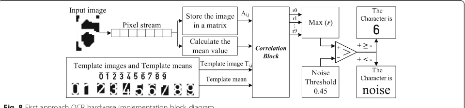
5.2.1 First approach
The block diagram for the OCR hardware implementation
first approach is depicted in Fig.8. First, the image of the
segmented character is fed to the OCR stage as a synthe-sized first-in-first-out (FIFO) stream with a depth of 1 bit [26]. Therefore, one pixel is written to the FIFO stream on a clock cycle and on the next clock cycle, it is unloaded and consumed. Therefore, the pixel is lost on the next clock cycle if its content is not stored after accessing it during this clock cycle. However, since each image is randomly accessed during the execution of the OCR stage more than once (during the calculation of the mean and the correlation coefficient), it is required to store the image. As the image is accessed and stored, the mean is calculated to optimize the time resource. The image is
stored as a hls::Mat variable data type provided by the
HLS Video Library. Afterwards, ten independent correl-ation opercorrel-ations are performed to correlate the stored input image with the ten pre-stored templates to identify the character in the image. The written function requires the two images and their mean as inputs and the address of the variable used to store the calculated correlation coefficient. Since the mean of each template image is required, the values are calculated using MATLAB and stored as constants. After calling the correlation function ten times and calculating ten coefficients, the maximum correlation coefficient is identified. Later, the maximum coefficient should exceed the selected noise threshold to verify that the image contains a character. Once verified, the character is identified; otherwise, it is assumed to
contain ‘noise.’ Table 4 shows the performance
esti-mates of the first approach hardware implementation
where Table 5 shows its hardware utilization. It is
worth noting that all variables used to perform the calculations are of the standard IEEE floating-point single precession data type.
As noticed in Tables 4 and 5 that the stage takes
around 1.5 ms to process one character and consumes about 25% of the PL fabric resources. The results show that the stage could be implemented using the PL unit but with more optimization and adjustments that are discussed in the following approach.
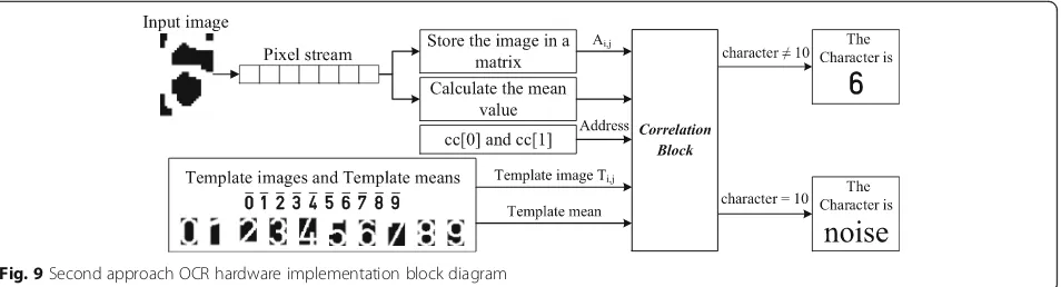
5.2.2 Second approach
In this approach, the target is to optimize the performance estimates and the hardware utilization of the first approach. Two observations achieved that. First, the steps followed to perform ten correlation operations and identify the charac-ter are not efficient since ten variables are used where only the maximum coefficient is significant. Moreover, the cal-culations performed using the standard IEEE floating-point single precession data type variables are not time efficient. The solution for this impediment is proposed through the next subsection.
The block diagram for the improved approach is
illus-trated in Fig.9. The first steps, where the input image is
stored and its mean is calculated, are the same as the first approach. Afterwards, a two-elements vector is ini-tialized to replace the ten variables of the first approach and find the maximum correlation coefficient. The pur-pose of the two elements is as follows:
– The first element—cc [0]: the element stores the maximum correlation coefficient calculated up to stepi(whereigoes from 0 to 9). First, its value is initialized to the selected threshold of noise to eliminate the step where the input image is verified to contain a character. Thus, the calculated correlation coefficient will be stored in the first element if and only if it exceeds the noise threshold. At the end (i= 9), the value of the first elementcc
[0]corresponds to the maximum correlation coefficient if the maximum correlation coefficient is greater than the noise threshold.
– The second element—cc[1]: the element stores the calculated coefficient for stepidespite its value. However, only if it exceeds the value that is stored in the first element (cc [0]), it is stored in the first element (cc [0]); otherwise, it is overwritten by the calculated correlation coefficient in the next iterationi+ 1.
After initializing the vector, the execution of the correl-ation block starts where it calls the written correlcorrel-ation function ten times. For each call, the following parameters are passed:
– The address of both input and characteritemplate images.
– The mean of both input and characteritemplate images.
– The address of vector cc.
– The character inside the template image.
Algorithm 5 shows the pseudo code of the correlation block algorithm. After the execution of the correlation block, if the value of the character is changed to be from 0 to 9, the input image character is recognized; otherwise,
the image is assumed to contain‘noise’where the value of
character is 10 (10 represents‘noise’).
Table6shows the performance estimates of the second
approach PL hardware implementation where Table 7
shows its hardware utilization. It is clear that the hardware utilization dropped from approximately 25 to 8% only as the redundant variables have been eliminated. Addition-ally, the performance has slightly improved due to the elimination of the test that verifies if the image contains a
character or‘noise.’
5.2.3 Second approach using fixed-point
After optimizing the hardware utilization, it is required to improve the OCR stage performance through redu-cing the time of processing one image and recognize the character. The first two approaches use the standard IEEE floating-point single precession data type. However, fixed-point data type will be used since it reduces the
computation time and optimizes the hardware utilization further. To use fixed-point variables, it is essential to determine the total number of bits for both integer and fractional parts, which introduces and controls calcula-tion errors. However, increasing the number of bits increases the time to perform the calculations. As a result, the number of bits used for both integer and fraction parts of the fixed-point variables should be optimized.
5.2.3.1 Fixed-point integer part optimization The proposed template-matching algorithm stores two types of values in fixed-point variables. The first type is constants such as noise threshold and means of template images and all of them are small (smaller than 1). However, the second type of values are related to the calculations of the input image mean and the correlation coefficients. These values vary from one input image to another. Equation (1) is used to correlate two images. Three variables are used to per-form the operation and calculate the correlation coeffi-cient. The first variable represents the numerator of Eq. (1) as shown in Eq. (2). The remaining two variables are used to calculate the denominator of Eq. (1) as shown in Eqs. (3) and (4). Later, the three variables are used in a loop to scan the two images matching them to find the correlation coefficient.
Num:¼XmXnAnm−A
|fflfflfflfflffl{zfflfflfflfflffl}
x
Bnm−B
|fflfflfflfflffl{zfflfflfflfflffl}
y
ð2Þ
Den:1¼XmXnAnm−A2¼
X
m
X
nx2 ð3Þ
Den:2¼XmXnBnm−B2¼
X
m
X
ny
2 ð4Þ
These four variables (the mean and the three variables used in the correlation operation) are the only fixed-point variables involved in the calculations. Therefore, they are considered to determine the total number of bits required to represent the integer part of the fixed-point variables. In this case, all fixed-fixed-point variables are defined to be of the same size. This is important to maintain the recognition rate of the stage. The four vari-ables control the accuracy of the calculated correlation coefficient as shown in Eqs. (2), (3), and (4).
The mean of the input image is calculated by adding up the pixels of the image and then dividing by the total number of the pixels in the image. Therefore, during the calculation of the mean of a binary fixed size image, the total number of pixels in one image is the maximum value that could be reached during the calculation. In this case, the value is 748 since the resolution of the images is 22 × 34 pixels.
For the other three variables, finding the maximum value is not straight forward. Equation (2) is the summation of
the multiplications of two different expressions (xand y).
Table 4First approach OCR algorithm performance estimates
Clock Latency (clock cycles) Total time (ms)
115.875 MHz 179,639 1.550
Table 5First approach OCR algorithm utilization estimates
Name BRAM_18K DSP48E FF LUT Overall
Total 9 30 16,874 22,567 39,480
Available 280 220 106,400 53,200 160,100
In addition, Eqs. (3) and (4) are exactly the same but in-stead of two different expressions, each equation has one
expression that is being squared (x→Eq. (3) and y→Eq.
(4). In this case, it could be stated that Eqs. (3) and (4) are special case of Eq. (2) where the two different images
became one image instead (A=B). To find the maximum
value of the equations, it is very critical to notice that in
case x>y, the multiplication in Eq. (3) will be the largest
among the three equations while ify>x, the largest value
for the multiplication is computed by Eq. (4). But what ifx
=y? In fact, this is the only case where the three equations
will have the same multiplication result. The last scenario is where the two images are perfectly matching or perfectly non-matching where the correlation coefficient is found to
be 1 or−1 respectively (the maximum value of the
correl-ation coefficient). Up to this point, it is known that finding the maximum of Eqs. (3) or (4) would immediately identify the maximum of the three equations since all of them have the same maximum. In fact, the maximum of the three equations is 187 which occurs when the mean of the image is 0.5. One way to find the maximum is to plot Eq. (3) or
Eq. (4) against the mean of the image as shown in Fig.10.
Therefore, the recorded greatest absolute number is 748. However, since the correlation coefficient is signed, 11 bits are required to represent the integer part as 1 bit is used for the sign and 10 bits determine the value. Subsequently, the range of numbers represented by 11
bits is [−1024, 1024].
5.2.3.2 Fixed-point fractional part optimization The optimization of the fractional part shown in Eq. (5) is more difficult than the integer part since it affects the recognition rate of the stage. Hence, the aim of this optimization is to maintain the recognition rate of the stage when compared to the software implementation
using MATLAB while achieving better performance estimates.
As a starting point, it was observed from MATLAB that the first four digits are different for any calculated correlation coefficients where the first three digits might be equal (bolded digits in Eq. (5). Therefore, they are considered the most important digits and should be error free in the fixed-point implementation of the algo-rithm. To have the first four digits error free, the fifth
digit should be error free which means the sixth digit’s
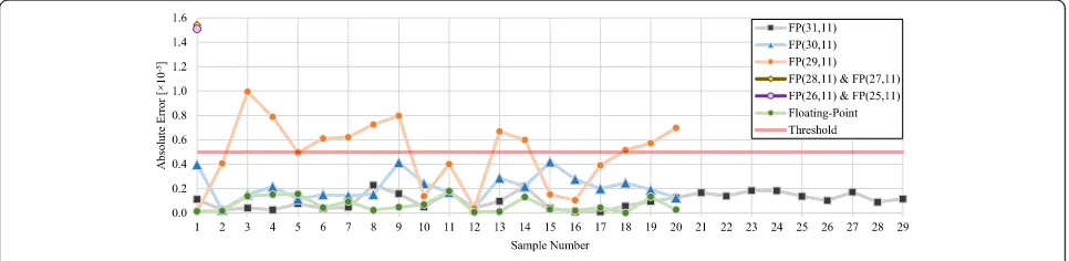
error should be limited. Despite that, the aim of using fixed-point variables is to reduce the performance esti-mates of the stage; however, the recognition rate should not drop due to the introduced errors. Therefore, the performance estimates will be found only after finding the size of the fixed-point variables that sustains the recognition rate of the OCR stage. The acquired results are analyzed by computing the absolute error when compared with the MATLAB results (Eq. (6). Then, the average and maximum absolute errors per fixed-point variable size are calculated using the results from several tests. However, after using the single precision floating-point variables to implement the algorithm, it is found that the error in the calculated correlation coefficients is
changing from one image to another as shown in Fig. 11.
Nonetheless, it is known that the use of single precision variables does not affect the recognition rate of the stage (as discussed in the PS implementation). Hence, a threshold
for the error is set based on the numbers’ common
rounding method. Based on the discussion of the four digits earlier, the error threshold is set to be a 5 in the sixth digit where any error larger than 5 is considered to affect the fifth digit. Therefore, two conditions for selecting the size of the fixed-point variable can be
Fig. 9Second approach OCR hardware implementation block diagram
Table 6Second approach OCR algorithm performance estimates
Clock Latency (clock cycles) Total time (ms)
115.875 MHz 179,288 1.547
Table 7Second approach OCR algorithm utilization estimates
Name BRAM_18K DSP48E FF LUT Overall
Total 10 17 4955 7630 12,612
Available 280 220 106,400 53,200 160,100
stated: first condition is that the error of the fixed-point implementation should be very close to the error of the single precision floating-point implementation. Second condition states that the error in calculating the correl-ation coefficient should be lower than the threshold to maintain the recognition rate. It is worth noting that the Vivado HLS tool denotes a fixed-point variable by two parameters N and I that corresponds to the total number of bits used to represent the variable and the number of bits used to represent the integer part respectively.
Correlation Coeff:¼X0:X−1X−2X−3X−4X−5X−6X−7…
ð5Þ
Absolute error¼MATLAB−fixed pointðN;IÞ ð6Þ
Random samples of images from the testing set are used to test the accuracy of the calculated correlation coefficients while implementing the algorithm using Vivado HLS. First, 31 bits are used to implement the fixed-point variables (11 bits for the integer part and 20 bits for the fractional part). Later, the number of bits used for the fractional part is reduced by one bit each time. The reduction process is controlled by the absolute
error per sample illustrated in Fig.11for all investigated
variables. However, to select the fractional part optimum
size, the maximum and average absolute error shown in
Fig. 12 are used. For the FP (25, 11), FP (26, 11), FP
(27, 11), and FP (28, 11) fixed-point variables, the first
sample rules them out as Figs.11and12illustrate that
their absolute error for the acquired results exceeds three times the selected threshold. However, for the FP (31, 11), FP (30, 11), and FP (29, 11) fixed-point
vari-ables, 20 samples are used first. From Fig.11, it is clear
that the absolute error of FP (29, 11) fixed-point vari-able exceeds the threshold for several samples and its maximum absolute error is greater than the selected threshold. Accordingly, FP (29, 11) fixed-point variable could not be used.
For the FP (30, 11) fixed-point variable, the absolute error per sample does not reach the threshold as shown
in Fig. 11. However, Fig. 12indicates that its maximum
absolute error is close to the threshold. Meanwhile, the number of samples used in this testing process is small; hence, there may be a case where the absolute error exceeds the threshold. Consequently, to be confident that does not happen, FP (31, 11) fixed-point variable is selected. Afterwards, additional nine samples are used to further test the algorithm using FP (31, 11) fixed-point variable. Eight samples are selected randomly where the ninth sample represents the worst case scenario of the testing set. If every testing set image is matched with the ten templates, there will be ten coefficients for each image. The worst case is when the difference between the highest two correlation coefficients out of the ten is the smallest. The image that has the smallest difference is the most likely affected by the introduced errors of the fixed-point variables. This image is found using MATLAB. For the 29 samples, the recognized characters by the OCR hardware implementation using FP (31, 11) fixed-point variables are the same as the MATLAB imple-mentation; hence, both implementations have the same 99.5% recognition rate.
After selecting the optimum size of the fixed-point variables, it is essential to find the performance and utilization estimates for the OCR stage hardware imple-mentation using fixed-point and analyze the improvements.
187
0 40 80 120 160 200
0 0.1 0.2 0.3 0.4 0.5 0.6 0.7 0.8 0.9 1
E
quatio
n (
3
)
The mean of the image
Fig. 10The maximum of Eq. (3) while varying the mean of the image
Tables8and9summarize the performance and utilization estimates for the FP (31, 11) fixed-point hardware imple-mentation respectively.
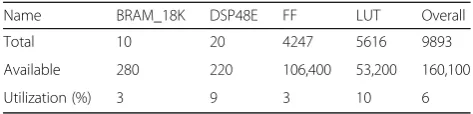
The impact of using fixed-point variables on the performance estimates of the OCR stage is clear. After using the fixed-point variable, the speed of the hardware implementation is around three times faster. Additionally, its effect is also noticeable on the hardware utilization as it dropped to reach 6% of the total available on chip resources. The usage of DSP slices increased slightly, whereas the utilization of other resources (flip flops (FF) and lookup tables (LUT)) has dropped significantly in this case when compared with the second approach imple-mentation using single precision floating-point variables. The Vivado HLS tool uses the DSP slices to perform the calculations when fixed-point variables are used instead of simulating the operations using FF and LUT. Additionally, by comparing the PS-based and the PL-based implemen-tations of the stage, it is clear that the PL-based imple-mentation using fixed-point variables outperforms all other implementations. It processes one plate with six characters in around 3.78 ms which is approximately six times faster than the PS-based implementation (25.68 ms) and almost two and half times faster than the PL-based implementation using the standard IEEE floating-point single precession (9.28 ms).
As the second approach to implement the OCR stage using fixed-point variables shows that the hardware utilization is 6%, and the processing time for one character is 0.63 ms, parallelism was not considered at this stage. Moreover, the segmented characters passed by the CS stage to the OCR stage are recognized sequentially where
each segmented character is correlated sequentially with the template images to identify the character. The main reason of avoiding the use of parallelism in the OCR stage only is that the performance of this stage and the first two stages satisfies the main aim of the work, which is devel-oping and implementing a real-time HD ANPR system using single SoC platform. The total hardware utilization of the system including the three stages is 18% of the available resources on the platform while processing one
frame in 17.56–19.94 ms. Thus, the use of parallelism will
not enhance the performance in general as it will reduce the processing time while increasing the hardware utilization where both parameters are met by the proposed system. However, it is worth noting that the proposed ANPR system is pipelined where the Vivado HLS tool takes care of this.
6 Results and Discussion
To evaluate the proposed OCR stage, a comparison based on the recognition rate, time performance, and hardware utilization of the proposed algorithm with already existing ones is conducted. However, since OCR is a common application used as part of a software application or implemented on hardware platforms, two comparisons are required.
Table 10 summarizes the software implementation of
the proposed OCR algorithm and some already existing algorithms showing their platform, recognition rate and processing time. It is worth noting that the proposed algorithm is capable of recognizing numbers only where in [5] for example, the proposed algorithm identifies 9 Arabic numbers and 25 English letters. Similarly, the
algorithms proposed in [27, 28] process both numbers
and letters from the Persian language. The proposed algorithm in [29] is capable of recognizing 10 Arabic numbers and 17 English letters. To compare the proposed algorithm in this work with other algorithms, the
algo-rithms proposed in [5, 14] were implemented by the
Fig. 12Average and maximum absolute error for the investigated variables
Table 8OCR hardware implementation performance estimates
Processing unit Variable type Clock (MHz) Latency (clock cycles) Total time (ms)
PS Floating-point N/A N/A 4.28
PL Floating-point 115.875 179,288 1.547
Fixed-point (31,11) 114.416 71,510 0.63
Table 9Detailed FP (31, 11) fixed-point OCR utilization estimates
Name BRAM_18K DSP48E FF LUT Overall
Total 10 20 4247 5616 9893
Available 280 220 106,400 53,200 160,100
authors to process the same characters targeted in this
work (the numbers from‘0’—‘9’). The same training and
testing character sets were used to train and test these algorithms. As it can be seen from the table, the proposed algorithm outperforms the existing algorithms in terms of recognition rate and processing time when processing numeral characters only.
Table11reports an overall hardware comparison between
the proposed algorithm and other existing algorithms. The numbers reported for the proposed algorithm in [12] show that it outperforms other systems. However, this algorithm was tested using 100 samples only, and it was reported that if the processed digit image is just slightly affected by noise, the performance degrades significantly. Therefore, its implementation in ANPR systems will affect their over-all performance, since characters processed in the OCR stage of such systems are noisy, as discussed earlier. Additionally, the algorithm reported in [30] has an increased hardware utilization compared to the work proposed in [5] and compared to this work. It uses 43 times the BRAM and twice the number of LUTs used in [5], even though the work in [5] uses a larger network on a bigger input image size. The large difference in utilization all goes to further ac-celerate its processing speed. This might be optimal for their implementation, as they implement only the OCR stage on hardware. However, this extra amount of required hardware resources might not be available practically for ANPR imple-mentations, since the remaining stages of the ANPR system (i.e., HD NPL and CS stages) should fit in the same single chip. Therefore, in this work the aim is to accelerate the implementation of the OCR stage to be fast enough to meet the real-time requirement of the ANPR system, while leaving enough on-chip resources in the SoC plat-form to implement the complete system. The hardware implementation of the proposed approach utilizes more BRAMs compared to [5] due to the storage of the
charac-ters’templates. Therefore, it is noticed that the proposed
stage compromises between hardware utilization and algorithm acceleration. Yet, it is outperforming other systems in terms of the recognition rate. This is due to the
nature of Qatari number plates which includes the ten
Arabic digits only, where the systems in [5,14,17,30] are
used to recognize English letters and Arabic digits.
From Tables 10 and11, it is concluded that the
het-erogeneous SoC platform is three times faster than a PC in implementing the proposed algorithm. Moreover, the PC is rated at 180 W where the heterogeneous SoC is rated at 36 W which means that the platform saves 80% of the energy consumed by the PC. Meanwhile, the
plat-form is 95% smaller than the PC used [31, 32]. Overall,
the heterogeneous platform is found to be faster, smaller, and more power efficient compared to the PC.
To sum up, it was found that the template matching-based algorithm can identify the segments that contain
‘noise’instead of characters which are detected due to dust
or scratches on the NP. Moreover, it recognized slightly rotated characters without the need for a stage to process rotated NP. Thus, the overall performance was found to be outstanding when compared with other algorithms while having an acceptable processing time to meet the real-time constraint for the ANPR system. However, this is valid when the total number of possible characters is limited. In case this number increases, other algorithms might achieve better results and be more efficient in terms of processing time and hardware utilization.
7 Conclusions and future work
This paper proposes four different algorithms to develop real-time HD ANPR system to recognize Qatari NPs. The proposed algorithms depend on two feature extraction (vector crossing and zoning) and one template matching techniques. The proposed algorithms were implemented using MATLAB to proof the concepts. The best algorithm has been selected and implemented on hardware. The Zynq-7000 All programmable SoC heterogeneous platform has been used to implement the whole real-time HD ANPR system. The heterogeneous platform consists of two separate processing units, PL (FPGA) and PS (ARM processor). Both PL and PS units were used to implement the template matching-based algorithm. The results of the Table 10Different OCR algorithms performance based on software implementation—MATLAB
OCR Platform Recognition rate (%) Processing time per character (ms)
[Proposed] template matching Intel Core i7 4770s 3.1 GHz 8 GB of RAM
99.50 1.95
[5] ANNa 97.49 7.46
[14] SVMa 98.75 7.49
[5] ANN Dual Core–2.4 GHz
3 GB of RAM
97.30 8.4
[27] Normal factoring Intel Core i3 2330M 2.2 GHz
2 GB of RAM
97.00 N/A
[28] Distance and angle features 99.00 N/A
[29] ANN N/A 94.32 N/A
a
Table 11 Overall comparison of OCR stages or systems hardware implementations OCR alg orith m Hardw are platfo rm Type of characters No. of testing char acte rs Charac ter size (cols ×rows) Recog nition rate (%) Proce ssing time per char acter (ms) BR AM DSP FF LUT [Propos ed] te mplate matc hing Zed board (Zynq-7000 ) 10 Arab ic digits 27 90 22 × 34 99.50 0.63
10 18-Kbit
20 (DSP48E) 42 47 5616 [ 5 ] ANN Mentor Graphics RC24 0 FPGA 25 Eng lish letter s and 9 Arab ic digits 35 70 22 × 34 97.30 0.7
4 18-Kbit
PL-based implementation were found promising. Therefore, more work was accomplished to improve the algorithm through modifying the steps and use optimized fixed-point data type variables. Accordingly, the acquired results show that the proposed OCR stage consumes 6% of the PL unit resources and it is capable of processing one character in 0.63 ms where the recognition rate was found to be 99.5%. The rest of the available on-chip resources could be used to implement other stages of the ANPR system. In addition, it is found that the heterogenous SoC saves 80% of the energy consumed by the PC used in this work and it is smaller by 95%.
Abbreviations
ANN:Artificial neural network; ANPR: Automatic number plate recognition; CCA: Connected component analysis; CS: Character segmentation; DSP: Digital signal processor; FF: Flip flops; FIFO: First-in-first-out; FPGA: Field programmable gate array; HD: High definition; HLS: High-level synthesis; HOR: Horizontal; ITS: Intelligent transportation system; LUT: Lookup tables; MIN: Minimum; NP: Number plate; NPL: Number plate localization; OCR: Optical character recognition; OpenCV: Open source computer vision; OS: Operating system; PL: Programmable logic; PS: Processing system; SD: Standard definition; SoC: System on chip; SOM: Self-organizing map; SVM: Support vector machine; VER: Vertical
Acknowledgements
This publication was made possible by UREP grant #17-138-2-037 from the Qatar national research fund (a member of Qatar foundation). The statements made herein are solely the responsibility of the authors.
Funding
This project was funded by Qatar National Research Fund (a member of Qatar Foundation) under the Undergraduate Research Experience Program (UREP) grant #17-138-2-037.
Availability of data and materials
The datasets of images used in this work is confidential and not available for public as it was provided by the Security Department at Qatar University.
Authors’contribution
AF was the main contributor to the algorithms proposed and their software and hardware implementations. He also wrote most of the manuscript. OH contributed in the PL hardware implementation and wrote the related work section in the paper. AAZ was involved in the PS hardware implementation. AAQ acquired and prepared the used dataset in addition to reviewing the manuscript. FB was the overall project coordinator. FB and AA had the overall academic supervision and revised the manuscript. XZ contributed to the PL hardware implementation. All the authors read and approved the final manuscript.
Ethics approval and consent to participate
Not applicable.
Consent for publication
Not applicable.
Competing interests
The authors declare that they have no competing interests.
Publisher’s Note
Springer Nature remains neutral with regard to jurisdictional claims in published maps and institutional affiliations.
Author details
1College of Engineering, Qatar University, Doha, Qatar.2Department of
Electronics, Computing and Mathematics, University of Derby, Derby, UK.
Received: 15 September 2017 Accepted: 26 June 2018
References
1. MAV Systems Ltd. ANPR Solutions. [Online] Available:http://www. anprcameras.com/anpr-solutions/, Accessed Oct 2016
2. United Kingdom Police. Automatic Number Plate Recognition [Online] Available: https://www.police.uk/information-and-advice/automatic-number-plate-recognition/#why-we-use-anpr, Accessed Oct 2016
3. United Kingdom Government. National Police Conference on Automatic Number Plate Recognition. [Online] Available:https://www.gov.uk/ government/speeches/national-police-conference-on-automatic-number-plate-recognition, Accessed Oct 2016
4. V Abolghasemi, A Ahmadyfard, An edge-based color-aided method for license plate detection. Image Vis. Comput.27(8), 1134–1142 (2009).https:// doi.org/10.1016/j.imavis.2008.10.012.
5. X Zhai, F Bensaali, R Sotudeh, Real-time optical character recognition on field programmable gate array for automatic number plate recognition system. IET Circuits Devices Syst.7(6), 337–344 (2013).https://doi.org/10. 1049/iet-cds.2012.0339
6. P Roy, F Rayar, J Ramel, Word spotting in historical documents using primitive codebook and dynamic programming. Image Vis. Comput.44, 15–28 (2015). https://doi.org/10.1016/j.imavis.2015.09.006.
7. X Zhai, F Bensaali, Improved number plate character segmentation algorithm and its efficient FPGA implementation. J. Real-Time Image Proc. 10(1), 91–103 (2015).https://doi.org/10.1007/s11554-012-0258-5 8. Z Jeffrey, X Zhai, F Bensaali, R Sotudeh, A Ariyaeeinia,Automatic number
plate recognition system on an ARM-DSP and FPGA heterogeneous SoC platforms(IEEE Hot Chips 25 Symposium (HCS), Stanford, CA, 2013), pp. 1–9. https://doi.org/10.1109/HOTCHIPS.2013.7478331
9. C Yan, H Xie, S Liu, J Yin, Y Zhang, Q Dai, Effective Uyghur language text detection in complex background images for traffic prompt identification. IEEE Trans. Intell. Transp. Syst.19(1), 220–229 (2018).https://doi.org/10.1109/ TITS.2017.2749977
10. L Eikvil,Optical Character Recognition, 1st edn. (Oslo, 1993).http://citeseerx. ist.psu.edu/viewdoc/summary?doi=10.1.1.25.3684
11. G Vamvakas, B Gatos, N Stamatopoulos, S Perantonis,A complete optical character recognition methodology for historical documents(2008 The Eighth IAPR International Workshop on Document Analysis Systems, 2008).https:// doi.org/10.1109/DAS.2008.73
12. N Toosizadeh, M Eshghi,Design and implementation of a new Persian digits OCR algorithm on FPGA chips(Signal Processing Conference, 2005 13th European, Antalya, 2005), pp. 1–4
13. X. Yafang.:‘Optical Character Recognition’, [Online] Available:http://web. eecs.umich.edu/~girasole/teaching/451/2014fall/gradprojects/optical_ character_recognition_final_report.pdf, Accessed June 2017 14. C Arth, F Limberger, H Bischof,Real-time license plate recognition on an
embedded DSP-Platform(2007 IEEE Conference on Computer Vision and Pattern Recognition, Minneapolis, MN, 2007), pp. 1–8.https://doi.org/10. 1109/CVPR.2007.383412
15. M Sarfraz, A Shahzad, M Elahi, M Fraz, I Zafar, E Edirisinghe, Real-time automatic license plate recognition for CCTV forensic applications. J. Real-Time Image Proc.8(3), 285–295 (2013).https://doi.org/10.1007/s11554-011-0232-7 16. D Kassymkhanova, D Kurochkin, N Denissova, S Kumargazhanova, A
Tlebaldinova,Majority voting approach and fuzzy logic rules in license plate recognition process(2014 IEEE 8th International Conference on Application of Information and Communication Technologies (AICT), Astana, 2014), pp. 1–5.https://doi.org/10.1109/ICAICT.2014.7035933
17. H Caner, H Gecim, A Alkar, Efficient embedded neural-network-based license plate recognition system. IEEE Trans. Veh. Technol.57(5), 2675–2683 (2008).https://doi.org/10.1109/TVT.2008.915524
18. O Hommos, A Al-Qahtani, A Farhat, A Al-Zawqari, F Bensaali, A Amira, X Zhai,HD Qatari ANPR system, vol 2016 (2016 International Conference on Industrial Informatics and Computer Systems (CIICS), Sharjah), pp. 1–5. https://doi.org/10.1109/ICCSII.2016.7462420
19. A Al-Zawqari, O Hommos, A Al-Qahtani, AAH Farhat, F Bensaali, X Zhai, A Amira, HD number plate localization and character segmentation on the Zynq heterogeneous SoC. J. Real-Time Image Proc., 1–5 (2018).https://doi. org/10.1007/s11554-017-0747-7
com/support/documentation/application_notes/xapp1167.pdf, Accessed Jul 2016
21. T Kryjak, M Komorkiewicz, M Gorgon, Real-time hardware–software embedded vision system for ITS smart camera implemented in Zynq SoC. J. Real-Time Image Proc. (2016).https://doi.org/10.1007/s11554-016-0588-9 22. OpenCV.‘OpenCV (open source computer vision)’. [Online] Available:http://
opencv.org/, Accessed June 2016
23. Linaro.“Linaro”. [Online] Available:https://www.linaro.org/, Accessed Mar 2017
24. OpenCV.‘Object Detection’. [Online] Available:http://docs.opencv.org/3.1.0/ df/dfb/group__imgproc__object.
html#ga586ebfb0a7fb604b35a23d85391329be, Accessed May 2017 25. Xilinx. Vivado High-Level Synthesis. [Online] Available:http://www.xilinx.
com/products/designtools/vivado/integration/esl-design.html, Accessed Apr 2016
26. Xilinx. Vivado Design Suite User Guide. [Online] Available:http://www.xilinx. com/support/documentation/sw_manuals/xilinx2014_1/ug902-vivado-high-level-synthesis.pdf, Accessed Apr 2016
27. R Azad, F Davami, B Azad, A novel and robust method for automatic license plate recognition system based on pattern recognition. Advances in Computer Science: an International Journal2(3), 64–70 (2013) 28. R Azad, B Azad, HR Shayegh,Real-time and efficient method for accuracy
enhancement of edge based license plate recognition system(2013 First International Conference on computer, Information Technology and Digital Media, 2013), pp. 146–155
29. HM Alyahya, MK Alharthi, AM Alattas, V Thayananthan,Saudi license plate recognition system using artificial neural network classifier(2017 International Conference on Computer and Applications (ICCA), Doha, 2017), pp. 220– 226.https://doi.org/10.1109/COMAPP.2017.8079759
30. Y Jing, B Youssefi, M Mirhassani, R Muscedere,An efficient FPGA implementation of optical character recognition for license plate recognition (2017 IEEE 30th Canadian Conference on Electrical and Computer Engineering (CCECE), Windsor, ON, 2017), pp. 1–4.https://doi.org/10.1109/ CCECE.2017.7946734
31. Dell Inc. OptiPlex 9030 All-in-One Desktop with Optional Touch Screen. [Online] Available:http://dell.to/2etCT0W, Accessed Nov 2016 32. ZedBoard. ZedBoard Technical Specifications. [Online] Available:http://