ISSN (e): 2250-3021, ISSN (p): 2278-8719
Vol. 08, Issue 6 (June. 2018), ||V (V) || PP 52-57
Micro Strip Patch Antenna with Multi-Split Ring Resonator
Using DGS for Multi Band Applications
Dr.K.P.Vinay
1, B.Ramesh
2, Lal Babu Prasad
3, K.S.Ravi Kumar
4, Prof. D.V.R.
K. Reddy
51
(Professor, Dept.of.ECE, Raghu Engineering College, Vizag, India)
2, 3,4(Assistant Professor, Dept.of.ECE, Raghu Engineering College, Vizag, India) 5(Professor, Dept.of. Instrument Technology, Andhra University, Vizag, India)
Corresponding Author: Dr.K.P.Vinay
Abstract-
An Innovative Micro strip patch antenna is designed to resonate at multi band using double split ring resonator (SRR) with center conducting patch. By inserting elliptical shaped ground along semi arc Defected Ground Structure (DGS) provides a good improvement in the return loss and impedance bandwidth. The antenna is simulated by using CST MW studio andis fabricated on FR4 substrate of size 30×30 mm2 with relative permittivity 4.3 and height 1.6 mm. The antenna parameters are measured using Vector Network Analyzer and the return loss values are -13.049dB, -20.436dB and -14.145dBat 3.26 GHz, 6.48 GHz, and 8.05GHz for S-band, C-bandand X-band applications respectively.Keywords
:
Defected Ground Structure-DGS, FR4, Multi Split-ring resonator, Elliptical shaped ground, Impedance Bandwidth--- Date of Submission: 07-06-2018 Date of acceptance: 23-06-2018 --- ---
I.
INTRODUCTION
In the present scenario demand of multiband wireless communications which supports more than one service, having different frequencies of operation simultaneously, gathers attention of many researchers. Simple in geometry to assure reliability and mobility characteristics Microstrip Patch Antenna (MPA) play a vital role due to its innate qualities like light weight, high gain, low profile, high efficiency, easy in fabrication and are easily well-suited for opto-electronic integrated circuits(OEICs) and microwave monolithic integrated circuits (MMICs) [1,2] due to its compact and elementary feeding techniques. This key feature of the microstrip patch antenna makes them applicable in many wireless communications such as Radio location, Space Research, Satellite communications, Radar and medical applications.
Many designs having a single conducting patch in different way to obtain multiband applications are investigated such as Circular ring with Y-shaped strip MPA[3], E-Shaped slot on fractal patch with H-Shaped and L-Shaped slots on the ground plane [4-6]. Square slot, triangular slot DGS [7]. Fan shaped patch with circular ring slot DGS [8], Inverted L-shaped slot patch [9], Dual Inverted L-shaped strip fed by cross-shaped strip line[10],[11], Fork shaped monopole antenna [12], Hexagonal MPA [13], Rectangular shaped DGS [14]. U-Shaped patch antenna with U-slot DGS [15], I-slot loaded MPA [16],
In this work, a compact MPA for Multiband frequency of operation is proposed. The conducting patch isetched to protrudent Split Ring Resonator (SRR) shape and fed with 50 ohm inline feeding technique. In addition, to this infinite ground plane was cut out semi arc shaped slot and by introducing elliptical shaped finite ground beneath the radiating element gives three resonant frequencies along with excellent impedance matching and directivity over the operating frequencies.
II.
ANTENNA DESIGN
The design parameter values of the schematic configuration of the antenna are listed in the table-1. Table-1 depicts the proposed antenna dimensions.
Dimensions Values (mm) Dimensions Values (mm)
LS 30 b 1.2
WS 30 c 3.5
LP 13.5 d 1
WP 26 s 0.5
Lf 13.5 g1 1
Wf 1 g2 0.8
Lg 13.4 r 9.5
Wg 30 r1 4.5
a 2 r2 8
Initially the proposed multiband MPA was first designed with rectangular patch of size LP×WP and the
ground plane is partially taken with Lg×Wg is fed with Microstrip line feeding technique.
In the second step, rectangular patch was etched to form dual split ring resonator and it is filled with rectangular strip inside it to generate dualband resonance.
In the third step, the return loss and the impedance bandwidth obtained in the step-2 was improved by introducingelliptical strip of radii „r1, r2‟ and cut out semi arc slot from the Partial Ground Plane (PGP) of radius
Figure.2: Design steps of the proposed antenna (a),(b) simple rectangular patch with partial ground plane in step-1 and (c),(d) are the front and back view of the optimized steps-2,3
All the above steps are optimized carefully to provide good impedance matching, S11 and directivity.
III.
RESULTS AND DISCUSSION
The simulation results of the proposed antenna are analyzed with the characteristic parameters of the MPA like S11, VSWR, gain and directivity.
Figure.3 depicts the 𝑆11 vs frequency comparison of the step by step optimized design of the proposed antenna with and without elliptical strip and semi arc in the ground plane. The simulation results shows that the introduction of elliptical strip and semi arc slot in the partial ground plane provides a uniform current distribution which leads to triple band resonant characteristics. The return loss at the frequencies 3.12 GHz, 6.38 GHz and 7.89 GHz with -18.72dB, -18.88dBand -14.53dBrespectively are depicted.
The figure.4 describes the VSWR of the MPA with Semi arc slot and elliptical strip DGS which depicts that the VSWR is less than 2 in all the three resonant frequencies at 3.12 GHz, 6.38 GHzand 7.89 GHz with 1.26, 1.25 and 1.46 respectively. This antenna is well suited for S-bandand C-bandin Radio location, satellite communication and Space research applications.
Figure.4: VSWR plot of the proposed MPA.
Table 2 depicts the simulation results of the proposed MPA with and without elliptical strip and semi arc slot DGS. It has been analyzed that there is a satisfactory improvement in the antenna parameters such as impedance bandwidth, gain and directivity.
Table-2 Simulation results comparison of the MPA with and without elliptical strip and semi arc slot DGS. Design Type Frequency
(GHz)
S11 (dB) VSWR Directivity
(dBi)
Bandwidth (MHz) MPA without
elliptical and semi arc DGS
3.12 6.38 7.89
-18.72 -18.88 -14.55
1.26 1.25 1.46
4.46 4.39 5.38
67.17 232 328.2 MPA with
elliptical and semi arc DGS
3.10 6.92
-11.07 -19.84
1.77 1.22
3.42 4.70
123 314
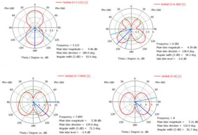
2-D radiation pattern of the proposed antenna was depicted in figure 5 and Directivity is monitored for frequencies at 3.12 GHz of S-band, 6.38 GHz, 7.89 GHz for C-band and 8 GHz for X-band.
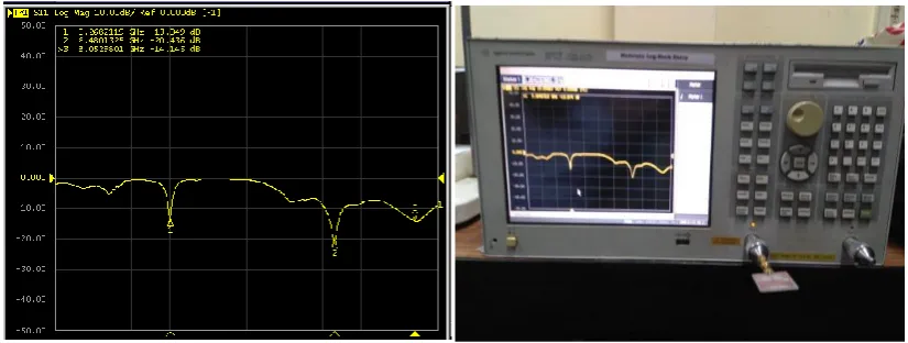
The fabricated antenna is tested and measured by using Vector Network Analyzer (VNA) is depicted in the figure 6 and the measured results are in good correlation with the simulated results is depicted in table 3.
Figure.6: Measured results of the fabricated antenna using VNA
Table 3 depicts the comparison between the simulation results and measured results Antenna Parameters Simulation Results Measured Results
Frequency (GHz) 3.12 GHz, 6.38 GHz, and 7.89 GHz
3.26 GHz, 6.48 GHz, and 8.05GHz
Return Loss lS11l (dB) -18.72 dB, -18.88 dB
and -14.55 dB
13.049dB, 20.436dB and -14.145dB
VSWR 1.26, 1.25 and 1.46 1.56, 1.20 and 1.48
IV.
CONCLUSION
In this novel work, MPA with dual SRR is designed with elliptical strip and semi arc DGS in the ground plane. The simulation results depicts that the antenna resonant at three frequency bands with lS11l are
-18.72 dB, -18.88 dB and -14.55 dB at 3.12 GHz, 6.38 GHz, and 7.89 GHzfrequencies respectively. By optimizing the radius of the semi arc slot and elliptical strip in the ground plane excellent improvement in the frequency resonance band is obtained near the X-band region. The fabricated results with lS11l are 13.049dB,
-20.436dB and -14.145dB at 3.26 GHz, 6.48 GHz, and 8.05GHzshow a good correlation with simulated results. The developed antenna can be used to operate at S-band, C-bandand X-band for satellite communication, Radio location and Space research applications.
REFERENCES
[1]. Constantine A. Balanis, “Antenna Theory: Analysis and Design,” John Wiley & Sons, 3rd Edition, 2005. [2]. Y. Liu, L. Si, M. Wei, P. Yan, P. Yang, H. Lu, C. Zheng, Y. Yuan, J.Mou, X. Lv and H. Sun, "Some Recent Developments of Microstrip Antenna",International Journal of Antennas and Propagation, vol.2012,10 pp.
[3]. Jing Pei, An-Guo Wang, Shun Gao, and Wen Leng,”Miniaturized Triple-Band Antenna With a Defected Ground Plane for WLAN/WiMAX Applications”, IEEE Antennas And Wireless Propagation Letters, vol. 10, 2011.
[4]. Mehr-e-Munir, Umar Farooq,” Multiband microstrip patch antenna using DGS for L-Band, S-Band, C-Band & mobile applications”,13th International Conference on Modern Problems of Radio Engineering, Telecommunications and Computer Science (TCSET), 23-26 Feb. 2016.
[5]. Ajay Nagpal, Sukhwinder Singh Dillon, Anupama Marwaha,” Multiband E-Shaped Fractal Microstrip Patch Antenna with DGS for Wireless Applications”, 5th International Conference on Computational Intelligence and Communication Networks, 27-29 Sept. 2013.
[6]. Varun Vaid, Sunil Agrawal,”Bandwidth Optimization using FractalGeometry on Rectangular Microstrip PatchAntenna with DGS for Wireless Applications”,International Conference on Medical Imaging, m-Health and Emerging Communication Systems (MedCom), 2014.
[8]. R. Kiruthika, T. Shanmuganantham, Rupak Kumar Gupta,” A Novel Dual Band Microstrip Patch Antenna with DGS for X-band Applications”, IEEE International Conference on Computer, Communication, and Signal Processing (ICCCSP), 2017.
[9]. Amit Singh Bhadouria, Mithilesh Kumar,”Multiband DGS Based Microstrip Patch Antenna forOpen Satellite Communication”, IEEE International Conference on Advances in Engineering & Technology Research (ICAETR), August 01-02, 2014.
[10]. Wen-Chung Liu, Chao-Ming Wu, and Yang Dai,”Design of Triple-Frequency Microstrip-Fed Monopole Antenna Using Defected Ground Structure”, IEEE Transactions On Antennas And Propagation, vol. 59, no. 7, July 2011.
[11]. Nikhil Pathak, Chandrasekaran.N, ”Multi-Band Antenna Using Defective Ground Structure.”, International Conference on Communications and Signal Processing (ICCSP), pp.1152 – 1155, 2015. [12]. Gajanan S. Kunturkar, Prasanna L.Zade, ”Design of Fork-shaped Multiband Monopole Antenna using
Defected Ground Structure”, International Conference on Communications and Signal Processing (ICCSP), pp.0281 - 0285, 2015.
[13]. Anuja Raj N,Ravi Prakash Dwivedi,”High Gain Antenna With Dgs For Wireless Applications”, 2nd International Conference on Signal Processing and Integrated Networks (SPIN), 2015.
[14]. Pragya Shilpi, Dharmendra Upadhyay, Harish Parthasarathy,”Design of Dualband Antenna with Improved Gain and Bandwidth using Defected Ground Structure”, 3rd International Conference on Signal Processing and Integrated Networks (SPIN) ,2016.
[15]. Ajay Thatere, Dr.P.L.Zade, Dwejendra Arya,”Bandwidth Enhancement of Microstrip Patch Antenna using „U‟ Slot with Modified Ground Plane”, International Conference on Microwave, Optical and Communcation Engineering, December 18-20, 2015.
[16]. Priyali Verma, Kirti Sharma, Anand Sharma, “I-Slot Loaded Microstrip Antenna For C-Band And X-Band Applications”, IEEE International Conference for Convergence of Technology, 2014.
![Network Protocol Security Testing [George Neville Neil] pdf](data:image/gif;base64,R0lGODlhAQABAIAAAP///wAAACH5BAEAAAAALAAAAAABAAEAAAICRAEAOw==)