Pushover Analysis of Steel Frame Structures
with Different Types of Bracing System
Mayank Chouhan Dr. Savita Maru
PG Student Professor
Department of Civil Engineering Department of Civil Engineering Ujjain Engineering College, Ujjain, M.P. India Ujjain Engineering College, Ujjain, M.P. India
Abstract
Steel is by far most useful material in construction and played an important role in last few decades. It must necessary to analyze and design a structure to perform well under seismic loads and also endow with well strength, stability and ductility for seismic design. The seismic performance of a multi-story steel frame structure is analyzed according to the provision of current Indian code (IS800-20007), seismic data and seismic factor from Indian code (IS1893-2002). Few guidelines like Applied Technology Council (ATC40) and Federal Emergency Management Agency (FEMA356) have used. Steel bracing is very useful for increasing the shear capacity of the structure. Bracing can be used as retrofit as well. There are few possibilities to arrange steel bracings such as X, V, Diagonal, K (Concentric bracings) and some eccentric bracings as well. Enough work has done in these types of bracings in several analyses. In this study typical G+8 story Steel frame buildings have analyzed, for various types of eccentric and concentric bracings. In this thesis Diamond bracing (Double K), Invert V, two types of eccentric bracings and a bare frame. Performance of each frame is studied through pushover analysis. In the present study five different types of model analyzed using pushover analysis. The pushover analysis has been carried out using SAP2000 v18, a product of computer and structure international. The results of all models are analyze and compare in term of base shear, story displacement, pushover curve, spectrum curve, performance point of the structure and story drift. If the overall performance of the buildings have found between LS -CP (Life safety – Collapse Prevent) structures is safe. The hinge results and location has been determined and it is noted that the most of the hinges begin to form in B-IO range at performance point.
Keywords: Pushover analysis, performance objectives high rise steel frame with different types of bracing, bracing pattern, performance point, displacement
________________________________________________________________________________________________________
I. INTRODUCTION
Nonlinear static pushover analysis gives a better view on the performance of the structures during seismic events. The seismic performance of a multi-story steel frame building is designed according to the provisions of IS 800 2007. Steel structures are more elastic than RCC structures but they show lateral deflection than RCC building. A bracing is an arrangement that is provided to minimize the lateral deflection of structure. A braced frame is a structural system which is designed principally to resist wind and earthquake forces. Braced frames are classified as concentric braced frames (CBF) or eccentric braced frames (EBF). Concentric braced frames are frames in which the core line of the member that get together at a joint, intersect at a point to form a vertical truss system which resist lateral forces. These frames provide complete truss action with member subjected to the axial forces in elastic range. Concentric braced frames (CBF) are used to resists wind forces. Bracing arranged concentrically in structure pose difficulties in preventing foundation uplift. Because one diagonal of an opposing pair is always in tension, possibility of brittle failure is present.
Eccentric braced frames(EBF) is a framing system in which the forces induced in the braces are transferred either to a column or to another brace through shear and bending in small segment of beam called link. The link in EBF act like structural fuses to dissipates earthquake induced energy in stable manner. EBFs represent an economically effective way of designing steel structure for seismic loading. Due to eccentric bracings there is reduction in the lateral stiffness of the system and improve the energy dissipation capacity.
II. PUSHOVER ANALYSIS
This paper includes the structural behavior of steel building for braced frame under lateral and static loading. The main aspire of study has been to recognize the type of bracing arrangement which causes minimum displacement such contributes to greater lateral stiffness to the building. This process aims to produce structures with predictable seismic performance. The three key elements of this method are: -
Capacity: - It is a representation of the structures ability to resist the seismic demand. Demand: - It is a representation of the earthquake ground motion.
Performance: - It is an intersection point of capacity spectrum and demand spectrum.
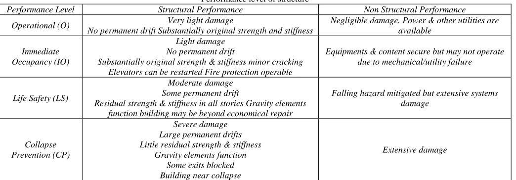
Different states such as Immediate Occupancy, Life Safety, Collapse prevention and collapse are defines as per ATC 40 and FEMA 356.
Table – 1
Performance level of structure
Performance Level Structural Performance Non Structural Performance
Operational (O) Very light damage
No permanent drift Substantially original strength and stiffness
Negligible damage. Power & other utilities are available
Immediate Occupancy (IO)
Light damage No permanent drift
Substantially original strength & stiffness minor cracking Elevators can be restarted Fire protection operable
Equipments & content secure but may not operate due to mechanical/utility failure
Life Safety (LS)
Moderate damage Some permanent drift
Residual strength & stiffness in all stories Gravity elements function building may be beyond economical repair
Falling hazard mitigated but extensive systems damage
Collapse Prevention (CP)
Severe damage Large permanent drifts Little residual strength & stiffness
Gravity elements function Some exits blocked Building near collapse
Extensive damage
Linear Dynamic analysis (Response spectrum)
Here the full design base shear and lateral force all along some principal direction is given in terms of design horizontal seismic coefficient and seismic mass of the building. Design horizontal seismic coefficient depends on the seismic zone importance factor of the structure, seismic zone factor of site, response reduction factor of the lateral load resisting elements and the fundamental period of the structure. The method usually used for the equivalent static analysis is given below:
1) Determination of fundamental natural period (Ta) of the buildings Ta = 0.075h0.075 Moment resisting RC frame building without brick infill wall.
Ta = 0.085h0.075 Moment resisting steel frame building without brick infill walls Ta = 0.09h /√d All other buildings including moment resisting RC frame building with brick infill walls.
Where,
h - Is the height of building in meter
d- Is the base dimension of building at plinth level in m, along the considered direction of lateral force. 2) Determination of base shear (VB) of the building
VB = Ah×W Where,
Ah=(Z/2)*(I/R)*(Sa/g) is the design horizontal seismic coefficient, which depends on the seismic zone factor (Z), importance factor (I), response reduction factor (R) and the average response acceleration coefficients (Sa/g). Sa/g in turn depends on the nature of foundation soil (rock, medium or soft soil sites), natural period and the damping of the structure.
3) Distribution of design base shear The design base shear VB thus obtained shall be distributed along the height of the building as per the following expression:
Where, Qi is the design lateral force, Wi is the seismic weight, hi is the height of the ith floor measured from base and n is the number of stories in the building.
Nonlinear Static Analysis (Pushover Analysis)
displacements, base shear, spectrum curve and ductility ratios. Plastic hinge hypothesis was used to capture the nonlinear behavior according to which plastic deformations are lumped on plastic hinges and rest of the system shows linear elastic behavior.
III. STRUCTURAL MODELING
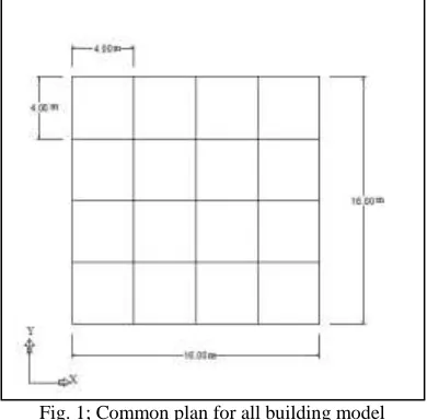
For the analysis work, five models of building (G+8) floors are made to know the realistic behavior of building during earthquake. In these study eccentric bracings, concentric bracings and bare frame has taken for the pushover analysis. Typically bay width is taken 4m in both X and Y direction. No of bays in both directions are 4. Total height of building is 31.9m. Story height (floor to floor) 3.1m were considered in this study. All the joints of beam column and bracings are rigid. There are assigned Diaphragm in all joints because; it is horizontal or nearly horizontal system which transmits lateral forces to vertical resisting system like bracing system. The models were analyzed as per Indian standard code and Fema356 and ATC 40. Different arrangement of steel braced frame and a bare frame considered below. All columns are fixed from base for foundation.
Fig. 1; Common plan for all building model
In this study a single model of bare frame and 4 models with different functional properties of bracing eccentric and concentric have taken.
(a) Diamond (Double K) (b) Invert V bracing (c) Eccentric type (d) Bare frame (e) Bracing at corner Fig. 2; Elevation of all buildings
IV. MATERIAL PROPERTIES
The material used in structure is steel in Beam, Column and Bracing member, the material considered in slab is concrete. Fe-345 grade of steel and M20 grade of concrete are used for all the frame models used in this study. The material properties are taken as per Indian Standard code IS 800 and IS 456. Parameters considered for the study is given below.
Table – 2
Building parameter considered for the study
Particular Details
Live Load 3 KN/M
2 At Typical Floor
1.5 KN/M2 On Terrace
Slab Thickness 150mm
Wind Load
Wind Loads.
Earthquake Load As Per Is-1893 (Part 1) – 2002
Depth Of Foundation Below Ground 3.1m
Type Of Soil Type II, Medium As Per Is:1893
Storey Height 3.2m
Plan Size 16m x 16m
No. of Bays in X Direction 4
No. of Bays in Y Direction 4
Grade Of Concrete M-20
Grade of steel Fe345 Structure steel
Column Size ISMB 550
Beam Size ISWB 500
Bracing Size ISMB 400
Building Importance Factor 1
Response Reduction Factor for concentric and eccentric respectively 4,5
Height of all buildings 31.9 m
V. ANALYSIS AND RESULTS
Procedure of pushover analysis
Define all the material properties, frame sections, load cases and mass source.
Assign hinge properties available in SAP2000 Nonlinear as per ATC-40 to the frame elements. For the beam default hinge that yields based upon the flexure (M3) and shear(V2) is assigned, for the column default hinge that yields based upon the interaction of the axial force and bending moment (P M2 M3) is assigned, and for the equivalent diagonal strut default hinge that yields based upon the axial force (P) only is assigned.
Define three static pushover cases. In the first case gravity load is applied to the structure, in the second case lateral load. After defining the all load cases run the analysis for the pushover load case and nonlinear gravity load case.
Pushover curve of all braced frame structure and bare frame structure have found after analysis. The capacity of the building is determined by pushover curve. All types of results are discussed below.
(c) Pushover curve of Bracing at corner (d) Pushover curve of Bracing Eccentric type
(e) Pushover curve of bare frame Fig. 3; Pushover curves of all buildings
In above figure pushover curves of all buildings have obtained, from the Pushover curve the data about displacement and base shear have obtained.
Capacity spectrum curve is useful for calculate the overall demand of the structure and capacity of the structure. It is useful to obtain the performance point of the structure. Spectrum curve of all buildings are discussed below in figures.
(c) Spectrum curve of bracing At corner (d) Spectrum curve of Eccentric bracing
(e) Spectrum curve of Bare frame Fig. 4: Spectrum curves of all buildings
Structure type Performance point (KN)
Displacement (mm)
Diamond bracing (Double K) 6925.922 0.084
Bracing at corner 6152.398 0.093
Invert V bracing 6488.383 0.089
Eccentric bracing 6173.156 0.092
Bare frame 6960.880 0.123
In the below figures shown that the location of plastic hinges formed for different performance levels in their final step of analysis for PUSH X direction. Whenever we check the performance of the structure we calculate the deformation of the hinges. If hinges are in O-CP (Operational to collapse prevent) stage, we can say that overall structure is safe. The various types of location and deformation of hinges are given below.
(b) Location of hinges obtained from building with bracing At corner
(c) Location of hinges obtained from building with bracing Invert ‘V’
(d) Location of hinges obtained from building with Eccentric bracing
From the above results the location of different types of hinges for different types of the buildings are obtained.
VI. CONCLUSION
1) Results obtained from the structure with diamond bracing (Double K) gives the minimum displacement 0.084mm at performance level. And the performance point obtained is 6925.922KN.
2) The result obtained from bare frame structure gives the maximum displacement 0.123mm at performance level. 3) The performance points are determined for all five building models.
4) The maximum value of performance point obtained from the structure having no bracing, bare frame structure is 6960.880KN.
REFERENCES
[1] Atc 40 (Applied Technology Council)
[2] Fema356 2000 (Federal Emergency Management Agency) “Pre Standard and Commentary for the Seismic Rehabilitation of Buildings”.
[3] Is1893 (Part 1) 2002 “Indian Standard Criteria for Earthquake Resistance Design Of Structures” General Provision and All Buildings.
[4] Is: 800 Indian Standard “Code of Practice for General Construction of Steel”
[5] Adithya. M, Swathi Rani K.S, Shruthi H K, Dr. Ramesh B.R, “Study On Effective Bracing Systems For High Rise Steel Structures”, Ssrg International
Journal Of Civil Engineering (Ssrg-Ijce) – Volume 2 Issue 2 February2015 Issn:2348–8352.
[6] Anshul Umredkar, Prof. Sandeep Gaikwad& Prof. Amey Khedikar “Investigation Of Steel Building Structures With Reference To Pushover Analysis”,
Imperial Journal Of Interdisciplinary Research (Ijir)- Vol-2, Issue-9, 2016.
[7] A. S. Moghdam and W. K. Tso “Pushover Analysis for Asymmetric and Set-Back Multi-Story Buildings”. 12wcee 2000, 1093.
[8] Chui-Hsin Chen., Jiun-Wei Lai., Stephen Mahin, “Seismic Performance Assessment Of Concentrically Braced Steel Frame Buildings”, The 14th World
Conference On Earthquake Engineering October 12-17, 2008, Beijing, China.
[9] D C Rai,S C Goel “Seismic Evaluation And Upgrading Of Chevron Braced Frames” Journal Of Constructional Steel Research 59 (2003).
[10] Ghobarah, Ahmed. (2001) “Performance-Based Design in Earthquake Engineering: State Of Development”. Engineering Structures 23 (2001) 878-884.
[11] Juan Carlos Vielma, Reyes Herrera, Sigrit Perez, Alex Barbat, Ronald Ugel, “Seismic Response Of High-Rise Steel Framed Buildings With Chevron-Braced
Designed According To Venezuelan Codes”, Vol.4, Special Issue, 694-698 (2012).
[12] K.G.Vishwanath, “Seismic Response of Steel Braced Reinforced Concrete Frames”, International Journal of Civil and Structural Engineering (2010).
[13] K.K Sangle, K.M.Bajoria And V.Mhalungkar., (2012) “Seismic Analysis Of High Rise Steel Frame Building With And Without Bracing” 15wcee, Lisboa.
[14] Mr. A. Vijay and Mr. K. Vijayakumar, “Performance of Steel Frame by Pushover Analysis for Solid and Hollow Sections”, International Journal of Engineering Research and Development, Vol. 8, Issue 7, Pp 05-12, September 2013.
[15] Pooja B. Suryawanshi, Prof. H. G. Sonkusaree, “Analysis Of Seismic Design Steel Braced Frame”, International Journal Of Science Technology & Engineering (Ijste)- Vol 2, Issue-11 May 2016.
[16] Pundkar R. S, Alandkar P. M “Influence Of Steel Plate Shear Wall On Multistory Steel Building”, International Journal Of Engineering Research And
Applications (Ijera) Issn: 2248-9622 Vol. 3, Issue 4, Jul-Aug 2013, Pp.1940-1945.
[17] R. Hasan, L. Xu, and D.E. Grierson “Push-Over Analysis for Performance-Based Seismic Design”. Computers and Structures 80 (2002) 2483–2493.
[18] Shih-Ho Chao and Subhash C. Goel, “A Seismic Design Method for Steel Concentric Braced Frames for Enhanced Performance”, 4th International
Conference on Earthquake Engineering, Taipei, Taiwan, October 12-13, 2006
[19] Shahrzad Eghtesadi, Danesh Nourzadeh, Khosrow Bargi (2011), “Comparative Study On Different Types Of Bracing Systems In Steel Structures”, World
Academy Of Science, Engineering And Technology (2011).
[20] Vaseem Inamdar And Arun Kumar (2014), “Pushover Analysis Of Complex Steel Frame With Bracing Using Etabs”.
[21] Zasiah Tafheem, Shovona Khusru (2013), “Structural Behavior of Steel Building with Concentric and Eccentric Bracing: A Comparative Study”, International