ANALYSIS OF EFFECTS OF VECTOR
CONTROL ON TOTAL CURRENT
HARMONIC DISTORTION OF
ADJUSTABLE SPEED AC DRIVE
KARTIK TAMVADA
Department of E.E.E, V.S.Lakshmi Engineering College for Women, Kakinada, Andhra Pradesh, India
R.KAMESWARA RAO
Department of E.E.E, Jawaharlal Nehru Technological University Kakinada (JNTUK), Kakinada, Andhra Pradesh, India
Abstract:
Adjustable speed drive (ASD) is becoming asignificant load component for power distribution. It involves the use of an Induction motor (IM). This paper involves modeling and control of an Induction motor and investigates its effects on the total current harmonic distortion of the adjustable speed ac drives. The simulation was carried out with the aid of the Simulink toolbox available in Matlab. It is seen that with Vector control the THDi of the drive reduces considerably.
Keywords:Adjustable Speed Drive; Matlab/Simulink; Modeling; Simulation; Vector control.
1. Introduction
Adjustable Speed drives are required in many applications. Adjustable speed drives produce current harmonic distortion. The use of ASDs leads to current harmonics pollution in the power grid and to electromagnetic interference (EMI) with the environment. Power quality and EMI are the constraints on electric induction motor drives. These loads are distributed all over an Electric network
Harmonics are undesirable as this interference with power apparatus can result in unacceptable levels of voltage distortion. Harmonic measurements require special equipment, which is quite expensive and not always available. This paper investigates the modeling and control of an Induction machine for an adjustable speed drive and harmonic analysis was carried out.
The multi-quadrant operation of drives is shown in Fig.1
Fig. 1. Multi-quadrant operation of Drives
2. Induction Machine
An electric drive may be operated in one direction of rotation or both directions of rotations depending upon requirements. Per-phase equivalent circuits widely used in steady-state analysis and design of ac machines, are not appropriate to predict the dynamic performance of the motor. A dynamic model is necessary to understand and analyze vector control of ac motor drives. A significant breakthrough was achieved in the analysis of three-phase ac machines through the development of the reference frame theory. The machine model can be transformed to another reference frame to using these techniques.
It is possible to simplify the complexity of the mathematical machine model by judicious choice of the reference frame. Initially these techniques were developed for the analysis and simulation of ac machines, but are now being extensively used in the digital control of such machines. The need for compact and accurate machine models is obvious, as digital control techniques are being extended to control current, torque and flux of the ac machines.
The induction motor is the most widely used motor type in industry because of its good self-starting capability, low cost, simple and rugged structure, and reliability, etc. Induction motors are used in adjustable speed applications where fast dynamic response is not required.
With the concept of vector control it is possible to control the induction motors to achieve dynamic performance comparable to that of dc motors. The dynamic model of the induction motor is necessary in order to understand and analyze vector control. The characteristics of induction motors are easily described by the dynamic model equations developed on a rotating reference frame.
3. The Concept of Harmonic
A harmonic is a component of periodic wave having frequency that is an integral multiple of the fundamental power line frequency of 50 Hz. The fundamental wave is pure sine wave without distortion. The 2nd harmonic differs in frequency and amplitude from the fundamental wave. It has two times the frequency and half the amplitude. The 3rd harmonic has three times the frequency and one-third the amplitude of the fundamental. Fig.2 depicts the fundamental, 2nd and 3rd harmonic.
Fig. 2. Summation of fundamental, second and third harmonic
4. Distortion Index
The most commonly used index for measuring the harmonic content of a waveform is the total harmonic distortion (THD). It is a measure of the effective value of a waveform and may be applied to either voltage or current.
Total harmonic distortion is the contribution of all the harmonic frequency currents to the fundamental. Just as waveforms can be added to produce distorted waves, distorted waves may be decomposed into fundamental and harmonic components.
4.1 Total Current Harmonic Distortion (THDi)
The THDi is a measure of the effective value of the harmonic components of a distorted waveform. This index can be calculated for either voltage or current. The following equation gives THD for current.
where Ih is the rms value of harmonic component h of the current.
The THD provides a good idea of how much extra heat will be realized when a distorted voltage is applied across a resistive load. Likewise, it can give an indication of the additional losses caused by the current flowing through a conductor.
5. Induction Motor Operation
An induction motor (IM) is only a part of an adjustable speed drive assembly. As such the IM is fed from power electronics converter (PEC), but indirectly in most cases from the industrial power grid.
Based on the J×B force principle, three operation modes of IM are easily identified (with Us – ideal no-load speed, U – mover speed):
• Motoring: |U| < | Us |; U and Us either positive or negative.
• Generating: |U| > |Us |; U and Us either positive or negative.
• Braking: (U>0 & Us <0) or (U<0 & Us >0).
current by inverter control. Since the control is obtained by controlling both phase angle and magnitude of current this method of control is called vector control.
Fig. 3. Motor with power supply
The main objective of vector control is to achieve superior performance under torque and speed change. For vector control of induction motor its model is considered in a synchronously rotating d-q reference frame.
The relation between torque flux and current components for an induction motor with squirrel cage rotor can be expressed as:
Where
6. Simulation
An adjustable speed drive consists of rectifier and inverter. Its functioning depends on the joint action of the rectifier and the inverter.
6.1 Rectifier
The rectifier is a six pulse full-wave diode bridge rectifier (p=6). It is represented in the form of a universal bridge in the simulation circuit shown in Fig.3. It converts the power supply ac voltage into dc voltage with a certain ripple. Traditional modeling for controlled rectifiers is a time-delay element in the s-domain.
6.2 DC link
The DC link is commonly called DC bus The diodes in the rectifier convert the input sinusoidal ac voltage to a rectified dc voltage which is then smoothed by the dc link in order to produce a dc voltage with lower ripple. It also acts as energy reserve to supply the inverter when the supply fails. ASD immunity against disturbances therefore depends on the energy stored in this circuit and energy demanded by the load.
In Fig.3 dc link is represented with an inductance L and a shunt capacitance C. Representation of the DC link filter is essential for the correct simulation of ASDs. It is the filter that makes the VSD harmonic current waveforms different from those of the DC drives.
6.3 Inverter
The inverter is controlled by the PWM scheme. In a sampling interval T= 1/ f C, the pulse width angle can be changed onlyonce. Therefore the PWM inverter is working in discrete state. The purpose of the inverter is to convert the low ripple dc voltage to adjustable ac voltage to allow the speed control of an induction motor.
The purpose of the inverter is to convert the low ripple dc voltage to adjustable ac voltage to allow the speed control of an induction motor.
The PWM inverter cannot be considered only as a proportional element. Since its output voltage is out of control once the pulse width is applied, it should be looked as a sample and linear-varying element.
The simulations of the ASD under normal operation and under vector control are shown in the Fig. 4 and Fig. 5 respectively.
Fig. 5. Simulation of PWM Inverter fed ASD
Fig. 6. Simulation of Vector Controlled ASD
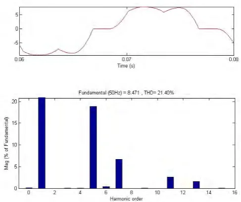
Fig.7. Input current waveform and harmonic spectrum for Phase B of PWM inverter fed ASD
Fig. 8 shows the input current waveform and the corresponding harmonic distortion spectrum for Phase B of Vector controlled ASD.
Fig. 8 Input current waveform and harmonic spectrum for Phase B of Vector controlled ASD
By evaluation of the harmonic distortion spectra of PWM inverter fed ASD and Vector controlled ASD it is clear that harmonic distortion levels fall considerably under Vector control scheme.
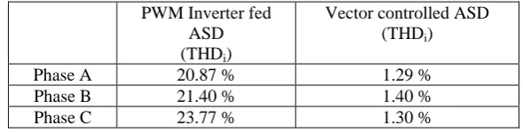
Table 1. Total current harmonic distortion levels for both the schemes
PWM Inverter fed ASD (THDi)
Vector controlled ASD (THDi)
Phase A 20.87 % 1.29 %
Phase B 21.40 % 1.40 %
Phase C 23.77 % 1.30 %
7. Conclusion
The issue of power quality has become more apparent due to the ever increasing number of non-linear loads. The low frequency harmonic current produced by these loads can cause damage to the power system equipment. Adjustable speed drive (ASD) is becoming a significant load component for power distribution. It is important to design these loads to reduce the problems arising from harmonic pollution. This paper involves simulation of ASD such that power quality is significantly improved.
References
[1] M.Farhney,”Design Considerations when Applying various ASD topologies to meet Harmonic Compilance”, Paper No. PCIC – 2010 – 15 Copyright material IEEE.
[2] Mukhtar Ahmed,”High Performance AC drives: Modeling, Analysis and Control”, Springer Publications, London, 2010.
[3] Yu Yu; Yang Zhao;” Harmonic and Interharmonic currents generated by the VSI fed Adjustable Speed Drives”, IEEE International Conference IPMEC’09, 2009, pp. 2464-2467.