A Precondition-based Approach to Workflow Oriented
Software Re-engineering
Feng Chen1, Da Tang2
, Hongji Yang1, and Mohammed Alawairdhi3
1 Software Technology Research Laboratory,
De Montfort University, Leicester, LE1 9BH, England { fengchen, hyang}@dmu.ac.uk
2 Department of Computer Science and Engineering,
Dalian University of Technology, Dalian 116024, China [email protected]
3 College of Computer and Information Sciences,
Al-Imam Muhammad Ibn Saud Islamic University, Saudi Arabia [email protected]
Abstract. Workflow management systems (WfMSs) become the basic technology for organisations to build their Information Systems. To understand the business processes already implemented in the existing software systems and then build the workflow oriented Information System is a time-consuming and error prone process. This paper proposes a unified software re-engineering approach from a business process perspective. A workflow extraction method is developed to elicit the business processes from existing systems. A precondition-based workflow model is designed for this purpose, which is an activity-centred method for program analysis. The calculation of the activity’s whole condition provides powerful analysis techniques to verify the correctness of the recovered workflow model. Through the proposed approach, the workflow procedures can be recovered from the existing system and verified by the precondition analysis.
Keywords: computer software re-engineering, workflow management, precondition-based workflow model, whole-condition of an activity.
1.
Introduction
applications, which is undesirable for the business change and integration [2]. Therefore, there is a clear need for re-engineering the underlying software systems to build the workflow oriented Information System, which is a time-consuming and error prone process.
This research proposes a unified software re-engineering method from a business processes perspective. The main goal is to recover business process from the existing system and then build the workflow oriented Information System. The focus is on the reverse engineering rather than the forward engineering. The remainder of this paper is organised as follows. In Section 2, the related work is discussed. In Section 3, a precondition-based workflow model is introduced. In Section 4, a workflow extraction method is presented to elicit the business processes from existing systems. The concept of whole-condition of an activity is defined to analyse the precondition-based workflow model for optimisation and verification. In Section 5, several examples are investigated and discussed to validate the proposed method. Finally, in Section 6, the conclusion is drawn and further research directions are advocated.
2.
Related Work
The technical context of the work is workflow oriented software re-engineering. In this section, the related research on business process engineering and software re-engineering, workflow modelling and verification, software re-engineering and business logic extraction (workflow mining and recovery) will be reviewed with particular focus on workflow management systems.
2.1. Business Process Re-engineering and Software Re-engineering
A business process, as defined by Hammer and Champy, means a series of interrelated actions that take inputs, add value to them, and produce outputs that are of value to the customer [37]. In 1993, these authors also triggered the concept of Business Process Re-engineering (BPR) when they published a book about the business revolution [17]. In the same period, Davenport [12] defined BPR as a process that “encompasses the envisioning of new work strategies, the actual process design activity, and the implementation of the change in all its complex technological, human, and organisational dimensions.” BPR is regarded as an essential enabler for new sorts of working together either inside or outside an organisation [22]. While BPR software is used for business process design, workflow management tools are used to automate the managing of the execution of the business process when it is in production and being used on a daily basis [13].
re-engineering the existing software to comply with the new business logic, there is a necessity to understand the business logic already implemented in the existing software systems.
Since the 1980’s, the topic of program understanding has attracted many software engineers. A number of theoretical and empirical approaches on analysis methods have been introduced to ease and facilitate the process of understanding software. There exist different abstract levels of understanding of a software source code. Therefore, there are different types of elicitable information, along with their supporting techniques that aim to provide program comprehension at any level of abstraction. For examples, logic view and algebraic view can be elicited from a source code. Logic view provides a mechanism of automated reasoning. This is achieved by the production of the inter-modular data flow information acquired by the static analysis of code [8]. Algebraic view is a formal representation technique that describes a program algebraic specification. Algebraic specification uses equations to denote the relationships between the operations that a domain provides [10]. The supporting technique for generating logic view or algebraic view is flow analysis. There are several automatic code flowchart generator tools. These tools can create code flowchart directly from the source code using a code analyser engine. Examples of such tools are Code Visual to Flow Chart (http://www.fatesoft.com) and Flowchart4j (http://www.codeswat.com).
In the area of software re-engineering, formal methods have been put forward as a means to formally specify and verify existing systems in particular those already operating in safety-critical applications, introduce new functionalities, and/or take advantage of the improvement in systems design techniques [25]. Formal methods can also increase the understanding of a system by revealing inconsistencies, ambiguities, and incompleteness that might go undetected [11]. By applying formal methods, it is possible to automate more of the process of software re-engineering [43].
2.2. Workflow Modelling and Verification
The purpose of workflow modelling is to model business processes and hence the modelling methods must have certain characteristics: simple, easy to use, sufficiently expressive, well-structured and logically correct. There are plenty of methods for workflow modelling, e.g. graph-based, Petri-net based, ECA rule based and logic-based method. All these methods describe workflow as a set of activities and transitions, and perform workflow schedule and execution based on various types of activities and transition rules.
of describing routing relations. It lets the activity be independent on routing, and hence its runtime scheduling algorithm [5, 21] is easy to be constructed, which is a natural way to build the big picture. Logic-based workflow models [27] are expressed with formulas and algebras, which are high-level abstract models for practical workflow, focusing on special characteristics for further analysis and mainly used in workflow theoretical research. Currently, temporal logic [36], predication logic [7], π calculus [42] and process algebra [40] have been used in workflow modelling. Strictly speaking, Petri-net can be treated as partial-order process algebra [6] and EAC rules can be expressed as transition rules or predication form of process algebra. The rule-based workflow model and the graph-based workflow model can be exchanged by defining the transformation rules.
Workflow models are usually denoted by graphical symbols and descriptive language. The commonly used languages are BPMN [30] and XPDL [38]. BPMN uses standardised graphical symbols to express business workflow processes. XPDL, defined by WfMC (Workflow Management Coalition), is an XML-based Workflow Process Definition Language, which can be used to exchange between different XPDL compliant workflow systems. XPDL comes from BPEL [29], which is currently the best file format for exchange of BPMN diagrams [38]. BPMN is a standard notation which is easily understandable by business users. As a result, BPMN bridges the gap between the business process design and process implementation by providing a standard notation. BPEL4WS is a Business Process Execution Language for Web Services. BPMN can express BPEL4WS visually with a common standard notation [39].
Correctness verification is important no matter which workflow modelling method is adopted. The verification mainly includes the reasonability on workflow structure [31] and restriction on workflow runtime [26]. Most of verification methods are based on graph theory and Petri-net [31]. As a research tool of workflow in theory, Petri-net is formally used to study the correctness of workflow definition, operational mechanism, and other problems [1]. The Petri-net makes the structural verification easier with its own characters. The time Petri-net and colored Petri-net can be used to analyse and verify the time aspect of workflow model [24]. More complicated Petri-net model is needed to express resource utilisation in workflow [32]. The workflow model based on Petri-net is conditioned and needs to be verified step by step [3]. In recent years, temporal logics, predicate calculus, and process algebraic approaches are also used as research tools for workflow verification [7, 36, 40]. Little work has been done on ECA rule based workflow verification.
2.3. Business Logic Extraction
Business logic extraction includes static method and dynamic method. Typically, a workflow represents a business process.
Static-Analysis Based Extraction. Sneed [33] presents an approach to recovering the business logic embedded in a legacy COBOL application. The approach is composed of four steps: restructuring, code slicing, multi-view analysis and integration. Single unified business logic documentation is generated from disjointed views at the transaction, subsystem and system level.
Zou [45] proposes a framework for model-driven business process recovery. In the framework, business logics are identified from the source code through a static tracing method and a number of heuristics. An Eclipse plug-in tool is developed to do an automatic extraction from Java-based Web applications. As an extension to a previous work, Zou [44] proposes another automatic approach that captures business processes from the source code of e-commerce applications. The approach runs a comparison between the structural features of both types of workflows, specified and as-implemented workflows. A structural comparison algorithm to recognise the structural resemblance between both types of workflows is designed.
Hung [18] introduces a method to recover business processes for the three-tier architecture systems. The automatic recovery is achieved by identifying the business data and business policies in the source code. The approach employs forward and backward tracing to identify the exact location of the business logics. Hung [19] presents another technique to recover workflows from three-tier e-commerce software systems. The approach and the developed prototype tool identify the structure of workflows by tracing the navigation flow of the UI through the different UI pages. The generated workflow is depicted using a hierarchical view, and can be imported into the IBM WebSphere Business Modeller to inspect its low-level processing tasks.
Dynamic-Analysis Based Extraction. In [34], Suenbuel and Shan propose an approach with experimental results for the extraction of high-level business process models from running enterprise systems. The complicated business processes are extracted using just a simple business process scheme and a few transformation and refinement rules. Based on this approach, a business process visualisation tool has been implemented. The tool automatically generates a Petri-net like diagram from the collected event data.
Similarly, Aalst et al. [4] develop techniques of discovering workflow models by using workflow logs. Workflow logs contain real-time information about the workflow process as it is being carried out. A new algorithm is provided by this approach to derive a process model from the workflow log and then it is represented in the form of a Petri-net. The results have demonstrated that the proposed process mining method is possible for structured processes.
analysing process flowchart structure as well as making the mining of complex business processes from event logs, that are incomplete, possible.
Foo et al. [15] introduce a technique for recovering business processes from e-commerce applications and for verifying the recovered processes using dynamic and static analysis. User interface (UI) design patterns are utilised to identify tasks with appropriate granularity, and to separate different business processes. In addition, in order to create a complete usage scenario of a business process, the recorded information from each tier is merged and sorted by access time. They also develop a tool named Process Explorer [16]. By employing static and dynamic analysis techniques the tool automatically recovers business processes found in e-commerce systems.
3.
A Precondition-based Workflow Model
Workflow oriented software re-engineering focuses on the reverse engineering process. In order to be successful in reverse engineering, the design of workflow model should meet following conditions:
the model should be formally defined to express general workflow specifications in terms of mathematical logic with suitable notations;
the model should support standard approaches to program analysis such as control-flow analysis, data-control-flow analysis, etc;
the model should be applicable to optimisation and verification that is relevant for reverse engineering methods;
the model should be easily and efficiently implementable.
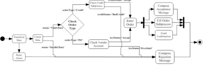
The precondition-based workflow model is designed to meet above conditions. To illustrate the precondition-based workflow model, in Fig. 1, an order registration system selected from WfMC (WFMCTC-1025, V1.0) is used as an example. Here, only the routing structure is analysed and the details of each task are neglected.
Fig. 1. Workflow process of order registration system
end activity. x1, x2, … x5 are variables of workflow control data that are relevant to the choice of branch condition. Without loss of generality, during workflow modelling, every branch condition is expressed by a different variable. In this paper, the definition of basic control flow constructs is the same as the definition by the Workflow Management Coalition (WfMC). There are four structures: Split, AND-Split, OR-Join and AND-OR-Join. The OR-Split is a point that only one of the alternative branches can be chosen, which is a XOR-Split. From Fig. 2, it is shown that the executive condition of a3 is that a2 is completed and x1=1; the executive condition of a8 is that a6 is completed and x4=1, or a7 is completed and x5=1, and the executive condition of a13 is that all a10, a11 and a12 are completed.
Fig. 2. Symbolised workflow process of order registration system
To sum up, the workflow model can be expressed as a composition of activities and their preconditions. An activity can be activated as long as its precondition becomes true. Since the execution of an activity is determined by its precondition, it is easy to judge the execution of an activity by checking whether the precondition of the activity is true or not. It means that the precondition-based workflow model can be constructed with only OR-Join and AND-Join structures. Meanwhile, since some preconditions of activities can be true at the same time, these activities can be dispatched concurrently.
Definition 1 (precondition-based workflow model): is defined as a 4-tuple: WF = <A, V, C, F >, in which:
A={a1, a2, …}: a finite set of activities;
let pre(a) = {a’| a’ is the direct pre-activity of a}, which is the direct pre-activity set of a;
let activity a’, a” A, if ai, i=0,1,…,k, so that a’ pre(a0), a0 pre(a1),…, ak pre(a”), then a’ is the pre-activity of a” and is written as a’ a”;
let saA, pre(sa)=, aA-{sa}, saa, sa is the start activity of the workflow model; let eaA, and aA-{ea}, aea, ea is the end activity of the workflow model; V={x1, x2, … }: a finite set of variables of workflow control relevant data;
let Di be the domain of xi, namely, Di =dom(xi);
C={c1, c2, … }: a finite set of conditions (predicate formula);
AC={< a’, c’>|a’pre(a), c’C}(AC), a’ is the direct pre-activity of a, c’ is the condition from a’ to a (default condition is True), (S) is the power set of S;
let fac:A(AC), fac(a)=AC={<a’, c’>|a’A; c’C}, fac(a)[a’]=c’; let ft: A{normal, andJoin, orJoin}, ft(a)=t, t{normal, andJoin, orJoin}.
By definition, the workflow model of Fig. 2 can be expressed as: WForder registration=<A, V, C, F>, in which:
A={a1,a2,…a15};
V={x1, x2, x3, x4, x5}, xiDi={0,1}, i=1,2,3,4,5;
C is a set of conditions: {x1=0, x1=1, x2=0, x2=1, x3=0, x3=1, x4=0, x4=1, x5=0, x5=1};
F={f(a1),f(a2),…f(a15)},
f(a1)=f(sa)=<, normal>, f(a2)=<{<a1, T>}, normal>, f(a3)=<{<a2, x1=1>}, normal>, f(a4)=<{<a2, x1=0>}, normal>, f(a5)=<{<a3, x2=1>}, normal>, f(a6)=<{<a5, x3=1>}, normal>,
f(a7)=<{<a5, x3=0>}, normal>, f(a8)=<{<a6, x4=1>,<a7, x5=1>}, orJoin>, f(a9)=<{<a8, T>}, normal>, f(a10)=<{<a9, T>}, normal>,
f(a11)=<{<a9, T>}, normal>, f(a12)=<{<a9, T>}, normal>, f(a13)=<{<a10, T>,<a11, T>,<a12, T>}, andJoin>,
f(a14)=<{<a3, x2=0>,<a4, T>,<a6, x4=0>,<a7, x5=0>}, orJoin>, f(a15)=f(ea)=<{<a13, T>,<a14, T>}, orJoin>.
Definition 2 (precondition-based workflow instance model): is defined as a 4-tuple: DWF=< I = AN, V, C, F >, in which:
V, C are defined the same as in Definition 1;
I=AN: (a, i)AN is defined as the i-th instance of activity a, here i is an identity for distinguishing the instances of the same activity;
F: the set of instances’ precondition, for any (a, i)I, f(a,i)=<IC, t >. f(a,i) is the precondition of an instance (a, i), fac(a,i), ft(a,i) are defined the same as in Definition 1. The precondition-based workflow instance model is designed to handle multiple cases executed in parallel way, which is quite useful for workflow simulation.
Definition 3 (instantiation of an activity): in DWF, let ent: AN{T,F}, ent(a,i)=F denotes that instance (a,i) has not been instantiated. Once ent(a,i)=T, it denotes that (a,i) has been instantiated. f(a,i) is met indicates that:
1)When ft(a) = normal, let pre(a) = {a’}, and fac(a)[a’] = c’, then ent(a’,j) c’=T. 2)When ft(a) = andJoin, let pre(a) = {a1’, a2’,…an’} and fac(a)[ a1’, a2’,…an’] =
[c1’, c2’,…cn’], then (c1’ ent(a1’,j))(c2’ ent(a2’,j))…(cn’ ent(an’,j)) = T. 3)When ft(a) = orJoin, let pre(a) = {a1’, a2’,…an’} and fac(a)[ a1’, a2’,…an’] = [c1’,
4.
The Workflow Oriented Software Re-engineering
In this section, the proposed precondition-based workflow oriented re-engineering method is presented. The method aims to facilitate the re-engineering of software systems in order to comply with the workflow technologies. The method follows a systematic step-based approach to extract business processes from an existing system by analysing the source code. The devised method is composed of 3 stages: program analysis for workflow elicitation, workflow analysis for optimisation and verification, system integration and testing. The system integration and testing stage is beyond the scope of this research and will be proposed as future work. Although this paper aims to be general and not limited to a specific programming language or software development approach, the focus is on Object-Oriented software and the reverse engineering aspect.
4.1. Program Analysis for Workflow Elicitation
Program analysis has the ultimate goal of enabling the comprehension of the underlying functional and data concept of software. Software visualisation can help software engineers to cope with the complexity of program comprehension by displaying programs, program artefacts, and program behaviour. Reverse engineering available techniques assist in software comprehension through exploiting the source code as the main source of information about certain software. The application of such techniques allows the extraction of a set of useful views provided to software engineers in the form of diagrams. The key step in the proposed approach is to extract the workflow models from the existing software. The extraction approach considers the source code to be the only available documentation for the system. The result of this step is a recovered workflow represented in the precondition-based workflow model.
Class Diagram Recovery and Class Grouping. A class diagram depicts the static structure of the core classes that are used to build an Object Oriented system. The attributes and methods of each class together with the optional indication of some of their properties such as visibility and type are provided in the class diagram. The relationships amongst the classes are also presented in the class diagram. Aggregation, association and dependency relationships are shown in a class diagram to indicate that a class has access to attributes or operations of other classes. The class diagram recovery can be achieved by a syntactic analysis of the source code, provided that an accurate definition of the interclass relationships is known.
There are three major types of classes defined by Rumbaugh, Jacobson and Booch [20] in their analysis model of an object-oriented design: boundary (interface) classes, control classes, and entity classes. Boundary classes are used to model interactions between the system and its actors (i.e., users and external systems). Boundary classes often represent abstractions of windows, forms, panes, communication interfaces, printer interfaces, sensors, terminals, and other APIs. Each boundary class should be related to one actor. Entity classes are used to model information that is long-lived and often persistent. Control classes are used to coordinate sequence and generally control the interaction between objects of other classes. Control classes typically encapsulate the business process of a single use case.
Grouping as a general term means grouping entities or objects according to their relationships or similarities, which has the same meaning of clustering. Grouping techniques have been applied in many areas of software engineering. For instance, it has been used to capture reusable legacy code segments in a legacy system. It is also applied in the program understanding area through decomposing large software systems into more manageable components. In software clustering literatures, several clustering algorithms focus on the utilisations of the software structure. The algorithms use structural dependences and relationships to decompose large software systems into a set of meaningful modular clusters. Approaches that used attributes other than the software structure have also demonstrated merit. Such approaches include grouping of software entities based on file names, ownership or functionality. The details of clustering method are out of the scope of this research.
Code Parsing and Abstraction. The control classes are more likely to hold the core business functions of the application. These classes should be pre-processed for further workflow extraction. The first step is parsing the source code and generating an Abstract Syntax Tree (AST) of the source code. Parsing or syntactic analysis as it is sometimes called is the process of analysing a sequence of tokens in order to determine its grammatical structure with respect to a formal grammar. The generated AST can be traversed by other tools to analyse the source code as a tree of nodes, where each node represents a part of the source code.
designed as the following abstraction algorithm. Although the developed algorithm is not limited to a specific programming language, Java will be used in this paper to describe the algorithm. Since some rules, e.g. utility code and exception code, may have exceptional situations, the implementation of the algorithm can highlight unsure segments of code for reengineer to make the final decision. The abstraction algorithm contains two levels of abstractions: class level and method level.
Algorithm 1: Code abstraction algorithm:
For each candidate class n filter out
/* Import Statements are used when a program refers to a class the compiler needs to determine which
package contains that class. */ 1: Import Statements
/* A getter is a method that gets the value of a specific property. A setter is a method that sets the value of a specific property. These methods are trivial for business process. */
2: Getters and Setter Methods
/* GUI components Creation is not related to business process. */
3: GUI Components Creation Methods
/* GUI layout Management is not related to business process. */
4: GUI Layout Management Methods For each candidate method m filter out
/* The purpose of variable declaration is to warn the compiler that the variable exists and to notify the compiler the type of that variable. */ 01: Variables Declaration
/* An exception is an event that occurs during the execution of a program that disrupts the normal flow of instructions. An exception object can be identified in try, catch and finally blocks in throw statements. Cases in which exception used to report error cases in the business logic handling are not handled in this algorithm. */
02: Exception Handling Statements
/* Utility Code Statements provide internal services, for instance, transaction initialisation,
rollback, commitment, tracing or logging.
Generally, utility methods are designed as public static methods. A catalog of utility classes can be established by consulting developers. */ 03: Utility Code Statements
/* A Java type class, such as Enumeration, String and Vector, provides primitive building blocks to construct a Java program. */
04: Type Objects Statements End For
Control Flow Diagram and Precondition-based Workflow Generation. Subsequent to the code abstraction step, control flow diagram will be automatically generated from the abstracted source code entities. Control flow diagram generation is an age-old problem. There are several automatic code flow chart diagram generators (software tools) that can reverse engineer a program with a code analyser and create a programming flowchart from the code. These available tools can be used to create control flow diagrams from the source code of the abstracted classes. Since the non-business logic code has been filtered out in the code abstraction step, the generated control diagram will most likely represent the business control logic embedded in the source code.
The final step of the method is to transform a control flow diagram into a precondition-based workflow model. Unlike the first three steps of the process, which were carried out automatically by using the appropriate software tools without the need for human intervention, in this research a software engineer with adequate knowledge in the domain of the application and the programming language used will be required. The job of the software engineer in this step is to simplify the extracted control flow diagram by replacing the code inside the diagram with more human readable expressions and activities.
4.2. Analysis of the Precondition-based Workflow Models
Once the workflow models are recovered, it is important to ensure that the produced models are correct, effective and efficient. For the system being reengineered, to analyse the recovered workflow process definition before it is put into production will greatly increase the quality of the new system.
Basically, there are three types of analysis: validation, verification, performance analysis [1]. Simulation and testing can be used for validation and performance analysis, which are supported by the precondition-based workflow instance model. For verification, more advanced analysis techniques are needed. Based on the definition of the precondition-based workflow, the execution of an activity is only related to its precondition. If an activity can be instantiated, it means that its precondition is met, which implies that some pre-conditions of the related pre-activities are met as well. In order to analyse the properties of a workflow in a whole, the concept of the whole-condition of an activity is presented, which is used to express the global property.
Whole-condition of an Activity. Informally, if WF is a precondition-based workflow model, the whole-condition of an activity a is defined as all conditions along the path from start activity sa to a that enable a to occur. The whole-condition of an activity is not only the executive condition of the activity itself, but it implicates that all conditions along the path should be met before the activity is instantiated, which covers more comprehensive information than activity precondition.
entry node and one exit node. The precondition-based workflow model includes three types of nodes: normal, andJoin and orJoin. A normal node has only one pre-activity by its definition, so it cannot be the entry to a loop. If a loop is entered via an andJoin node, the loop body can never be executed since one node within the loop body must be triggered before the precondition of the entry node (andJoin node) is met. Therefore, only the cyclic structures with orJoin-type nodes as entry points are taken into account in the paper. Some related concepts are given below first.
Definition 4 (an acyclic path and its whole-condition): WF=<A, V, C, F> is a precondition-based workflow model. An acyclic path of an activity a( A) is defined as a route from the start activity sa to a without loop. Assuming there are m paths from sa to a, the condition of ith path (i=1,2,…m), written as pcond(a,i), is defined as a conjunction of all conditions along the whole path.
The whole-condition of a is defined as a disjunction of all path conditions: wc(a)=pcond(a,1)pcond(a,2)…pcond(a,m). If any of path conditions of a is true, the whole-condition of a is true. In other words, if the whole-condition of a is satisfied, the precondition of a is satisfied, and a can be initiated and executed.
Algorithm 2: WF=<A, V, C, F> is a precondition-based workflow model. For every aA, the method of calculating the whole-condition of acyclic paths of a is given below. Here, wc(a) denotes the whole-condition of a:
1) The whole-condition of start node sa is: wc(sa) = T.
2) When ft(a)=normal, namely, a is a normal type, let pre(a)={a’}, and fac(a)[a’]=c’. Then the whole-condition of acyclic paths of a is: wc(a) = c’ wc(a’).
3) When ft(a)=andJoin, let pre(a)={a1’,a2’,…an’} and fac(a)[a1’,a2’,…an’]=[c1’, c2’,…cn’], the conditions of the acyclic branches of a are wci(a)=ci’wc(ai’), i= 1,2,…n, the whole-condition of the acyclic paths of a is:
wc(a)=wc1(a)wc2(a)…wcn(a)=c1’wc(a1’)c2’wc(a2’)…cn’wc(an’). 4) When ft(a) = orJoin, let pre(a)={a1’,a2’,…an’} and fac(a)[a1’,a2’,…an’] = [c1’,
c2’,…cn’], the conditions of the acyclic branches of a are wci(a) = ci’ wc(ai’), i= 1,2,…n, the whole-condition of the acyclic paths of a is:
Definition 5 (a cycle and its whole-condition): WF= <A, V, C, F> is a precondition-based workflow model with cyclic structures. A cycle of a is defined as a route from a, through a loop of activities, to a itself, assuming there are n cycles of a, The condition of jth cycle, written as lcond(a, j), (j=1,2,…n), is defined as a conjunction of all conditions in the cycle, i.e., lcond(a, j) is calculated as the whole-condition of a path from start node a to end node a itself. Let oa be an orJoin-type node and an entry point of n cycles, awc(oa) denotes the whole-condition of the acyclic path from sa to oa, the whole-condition of a through j-th cycle is defined as: wc(oa, j) = lcond(oa, j) awc(oa).
Naturally, wc(oa) can be defined as: wc(oa) = lcond(oa, 1) lcond(oa, 2) … lcond(oa, n) awc(oa), (j=1,2,…n). In this paper, the discussion is focused on the whole-condition of one cycle, i.e. wc(a, j).
Algorithm 3: WF=<A, V, C, F> is a precondition-based workflow model with cycles. oa is an orJoin-type node and an entry point of cycles. For every node aA, there exist 3 cases: aoa, a=oa and oaa. The method of calculating the whole-condition of j-th cycle is given below.
1) When aoa, there is no loop from sa to a, wc(a) can be calculated with Algorithm 2.
2) When a=oa, as defined in Definition 5, wc(a, j) = lcond(a, j) awc(a).
3) When oaa, xwc(a) denotes the whole-condition of the acyclic path from oa to a, wc(a, j) = awc(oa) xwc(a) lcond(a, j). awc(oa) xwc(a) is the whole-condition of acyclic paths from sa to a.
In the precondition-based workflow model, workflow relevant data are an important factor to affect the workflow execution. Workflow relevant data can be accessed by both applications and the workflow engine. Workflow relevant data are associated with the workflow instance, and different values of relevant data can influence the routing of instances. Since the values of workflow relevant data in loop condition may change in later execution, to simplify the expression, it is necessary to introduce predicate variables in lcond(a, i) for analysing workflow models with cyclic structures. In this way, the relevant data can be assigned many times. For example, there are two variables in lcond(a, 1), x{1, 2, 3}, y{T, F}, x=1, y=T. lcond(a, 1) can be expressed as lcond(a, 1): X|x = 1, Y|y = T, in which, X indicates a predicate variable with the domain
of {1, 2, 3}, and the current value of X is x=1, Y indicates a predicate variable with the domain of {T, F}, and the current value of Y is y=T. X and Y are called as associated predicate variables.
Precondition-based Workflow Verification. In a broad sense, the verification of a workflow model is to ensure that the whole process, from the model setup/instantiation to the end of execution, is correct. The definition of correctness is a set of minimal requirements that the precondition-based workflow model should satisfy. Most of definitions from literature can be described as the following three soundness properties:
liveness means that, for every activity a, there is an executable path from start node sa to a, and then to the end node ea of the workflow.
b) Workflow model without wrong synchronisation. Wrong synchronisation means that concurrent activities cannot be converged in an andJoin-type node but in an orJoin-type node.
c) Workflow model without infinite loops. For a workflow model with cycles, each cycle should have at least one exit.
Point a) and point b) are easy to be understood. For point b), if an orJoin activity a4 is preceded by activities a2 and a3.The predecessor of activities a2 and a3 is an andSplit activity a1. As a result, both activities a2 and a3 will run in parallel, and activity a4 has to be instantiated twice. This is not desirable and is defined as wrong synchronisation. In a precondition based workflow model, there is no definition of andSplit and xorSplit. Actually, the information of andSplit and xorSplit has been implicitly expressed in the preconditions of activities.
Only all above requirements are met, a workflow can be defined as correctness. Obviously, the soundness property relates to the workflow instance model. Definition 6 gives a definition of the correctness of the precondition-based workflow.
Definition 6 (correctness of the precondition-based workflows): if a precondition-based workflow instance model DWF meets the following conditions:
a) For every activity aA, asa, aea, if there exists a state ent(a,i) = T, then this state is derived from ent(sa,1) = T and leads to the terminal state of DWF, namely, ent(ea,1) = T. This point indicates that the precondition-based workflow is live.
b) For every aA, a’, a’’ pre(a), ft(a)= orJoin, fac(a)[a’,a’’] = [c’, c’’], that <(a’, k),c’> and <(a’’, l),c’’> cannot be satisfied simultaneously. This point asserts that the precondition-based workflow has no wrong synchronisation.
c) It will not happen that ent(a,i) = T can always reach to a new state, ent(a,i+1) = T (i >= 1). This point ensures that there is no infinite loop for the workflow instance.
Then, the workflow model is correct.
Theorem 1 (correctness of workflows without cyclic structures): let WF be a precondition-based workflow model without cyclic structures and ACOND be a set of whole-conditions of activities in WF. wc(a)=wc(x1,x2,…xn)ACOND denotes the whole-condition with relevant data xiV (i=1,2,…n) as variables, and Di as the domain of xi. Then, WF is correct if the following conditions are met for every xi (i=1,2,…n) with an assigned value in Di:
1) For any activity aA, there exists xi (i=1,2,…n) with an assigned value, such that wc(a)=T.
2) For any activity aA with andJoin type, wc1(a)wc2(a)…wcn(a)=T, otherwise wc1(a)=wc2(a)=…wcn(a)=F.
Proof: To prove the correctness of a workflow model is equal to prove that the workflow model meets the 3 conditions of definition 6.
It is obvious that the c) of definition 6 is met for a workflow model without cyclic structure.
According to 1), for an instance (a,1), ent(a,1) = T, there exists a pre-instances (a’,1), which has been instantiated, and so on. So ent(a,1) = T can be derived from ent(sa,1) = T. On the other hand, for aj that apre(aj), j=1,2,…k, there exist values of cj(xi), such that ent(a,1)cj = T, j=1,2,…k. If ft(aj)= normal or ft(aj)= orJoin, f(aj,1) must be met, namely, wc(aj)= T. If ft(aj)=andJoin, according to 2), wc1(a)wc2(a)…wcn(a)=T, wc(aj)= T. So ent(ea,1) = T can be derived from ent(a,1) = T. Therefore, the a) of definition 6 is met.
For the orJoin-type node, the 3) indicates that different path conditions cannot be met at the same time. For a’, a’’ pre(a), ft(a)= orJoin, a’ and a’’ are not in the same path, <(a’, j), c’> and <(a”, k), c”> cannot be met at the same time, namely, the b) of the definition 6 is met.
Proof End
Theorem 1 gives the sufficient conditions judging the correctness of a precondition-based workflow model without cyclic structures. 1) and 2) of the Theorem 1 guarantee there is no deadlock in the workflow model. 3) of the Theorem 1 guarantees there is no wrong synchronisation. For an orJoin-type activity, if the full conditions of two paths are true simultaneously, this activity will be instantiated twice, which is treated as wrong synchronisation.
Since the whole-condition of an activity is a predicate formula, the correctness of workflow models can be evaluated by analysing the activities’ whole-condition. This theorem would be very useful since the problem of the workflow verification can be translated into the problem of predicate determination by this theorem.
For a workflow model with cyclic structures, the following theorem ensures that a workflow model with cyclic structures is correct.
Theorem 2 (correctness of workflows with cyclic structures):let WF be a precondition-based workflow model with cyclic structures. If a workflow model is correct, it should meet the following requirements:
1) For every (a, i), lcond(a,i) = F, the workflow model is correct.
2) For every orJoin-type node oa, the substructure, which begins from oa with whole-condition of T and ends at oa itself with the whole-condition of lcond(oa,i), is correct.
3) For an orJoin-type node oa, on which there is a cycle with the condition lcond(oa,k), for every andJoin-type node a after oa, if a is inside the cycle, when lcond(oa,k) is true, [lcond(oa,k) T] [wc1(a,k) wc2(a,k) … wcm(a,k)] must be true. if a is outside the cycle, when lcond(oa,k) is false, [lcond(oa,k) F] [wc1(a,k) wc2(a,k) … wcm(a,k)] must be true. wc1(a,k), wc2(a,k), …, wcm(a,k) are branch conditions of a. This indicates that item 2) in Theorem 1 is hold with cyclic structures.
5) lcond (a,i) is not a tautology. Namely, If lcond (a,i) = F, there exists b, such that wc(b) = T.
Proof: To prove the correctness of a workflow model is equal to prove that the workflow model meets the 3 conditions of definition 6.
According to 1), 2), 3), both acyclic and cyclic branches and their combination are correct. Based on Theorem 1, It is obvious that ent(a,1) = T can be derived from ent(sa,1) = T and ent(ea,1) = T can be derived from ent(a,1) = T. Meanwhile, there is no wrong synchronisation. Therefore, the a) and b) of definition 6 is met.
According to 4) and 5), there is no infinite loop in the model. Therefore, the c) of definition 6 is met.
Proof End
5.
Examples
First, a small example of a thesis defence application is selected as the case study to experience the proposed approach. The goal of this example is to demonstrate the feasibility of the proposed approach for software re-engineering. Then, several representative examples are used to illustrate the abilities and the limitations of the whole-condition based analysis methodology.
5.1. A Thesis Defence Application
The thesis defence application was taken from a university’s office automation system. A modification was made to make the code more suitable for evaluating the proposed approach. The scenario for this case study is to reengineer a Java based system to extract the workflows by employing the precondition-based workflow oriented software re-engineering approach.
Fig. 3. A flowchart of the thesis defence application process
Then a precondition-based workflow model can be created formally after analysing the activities of business processes in above application:
WFApplyforDefence=<A, V, C, F>, in which:
A={Start(sa), AppForDefense, ThesisModi, NotpassEval, FormatModi,
AppInSuccess, TutorOpinion, Review1, Review2, Evalution, FormatCheck, End (ea)}, V={opinion, format, g1, g2},
Dopinion= {yes, no}, Dformat = {yes, no}, Dg1 = {1..5}, Dg2 = {1..5},
C is a set of formula generated from following atomic formula: T, F, opinion=‘no’, opinion=‘yes’, format=‘no’, format=‘yes’, g1>2, g2>2, g1+g2>7,
F={f(sa), f(AppForDefense), … f(ea)},
f(sa)=<, normal>, f(AppForDefense)=<{<sa, T>}, normal>, f(TutorOpinion)=<{<AppForReply, T>,<ThesisModi, T>}, orJoin>, f(ThesisModi)=<{<TutorOpinion, opinion=‘no’>}, normal>, f(Review 1)=<{<TutorOpinion, opinion=‘yes’>}, normal>, f(Review 2)=<{<TutorOpinion, opinion=‘yes’>}, normal>, f(Evalution)=<{<Review1, T>,< Review2, T>}, andJoin>,
f(FormatCheck)=<{<Evalution,((g1>2)(g2>2)) (g1+g2>7)>, <FormatModi, T>}, orJoin>,
f(FormatModi)=<{<FormatCheck, format=‘no’>}, normal>,
f(NotpassEval)=<{<Evalution,(((g1>2)(g2>2))(g1+g2>7))>}, normal>, f(AppInsuccess)=<{<FormatCheck, format=‘yes’>}, normal>,
Workflow Verification. For the thesis defence application workflow model, the whole-conditions of acyclic paths in the workflow are calculated as below:
wc(AppForDefense)=T, wc(TutorOpinion)= T, ...
wc(FormatCheck)=(((g1>2)(g1>2))(g1+g2>7))(opinion=‘yes’), … wc(ea)={(format=‘yes’)(((g1>2)(g1>2))(g1+g2>7))(opinion=‘yes’)} { (((g1>2)(g1>2))(g1+g2>7))(opinion=‘yes’)}
The whole-conditions after one cycle for orJoin-type nodes are calculated as below: wc(TutorOpinion, 1)=(opinion=‘no’),
wc(FormatCheck, 1)=(format=‘no’)(((g1>2)(g1>2))(g1+g2>7)) (opinion=‘yes’).
In this example, there are two loops produced separately on orJoin-type nodes: TutorOpinion and FormatCheck. Let variable Option be assigned with values of {opinion=’no’, opinion=’yes’}, and Format be assigned with values of {format=’no’,format=’yes’}. The cyclic condition lcond(TutorOpinion,1): opinion=’no’ can be re-expressed as lcond(TutorOpinion,1): Opinion|opinion=’no’. The
cyclic condition lcond(FormatCheck,2): format=’no’ can be re-expressed as lcond(FormatCheck,2): Format|format=’no’. Because two cycles are produced on different
nodes, there is no interaction between each other, two whole-conditions can be put together with different label i{1,2}. For example,
wc(TutorOpinion, i)=wc(TutorOpinion)lcond(TutorOpinion, 1) =T Opinion |opinion=‘no’= Opinion |opinion=‘no’.
The following is the verification of the precondition-based workflow model with two cycles on nodes: TutorOpinion and FormatCheck:
It is easy to verify that 1) of the Theorem 2 is met.
The cycle from TutorOpinion, through ThesisModi, to TutorOpinion can be regarded as a non-cyclic structure from TutorOpinion with whole-condition T, to TutorOpinion itself with whole-condition opinion=‘no’. It is easy to verify that this sub-structure is correct. Similarly, FormatCheck can also be verified to be correct. Thus, 2) of the Theorem 2 is met.
Since wc1(Evaluation) wc2(Evaluation), item 3) of the Theorem 2 is met.
If wc(TutorOpinion) lcond(TutorOpinion,1) opinion=‘no’, then wc(ea)=F, and if wc(FormatCheck) lcond(FormatCheck,2) ((g1>2 g2>2) (g1+g2>7)) (opinion=‘yes’) (format=‘no’), then wc(ea)=F, therefore, 4) of the Theorem 2 is met.
If lcond(TutorOpinion,1) opinion=‘no’ and lcond(FormatCheck,2)
format=‘no’, then lcond(TutorOpinion,1) lcond(FormatCheck,2) (opinion=‘no’) (format=‘no’) is not a tautology, namely, 5) of the Theorem 2 is met.
The verification is over showing that the model is correct.
5.2. Several Representative Workflow Models
(a) (b)
Fig. 4. Workflow models without cycles
Fig. 4(a) is a workflow model with overlapping structure. No matter what value, T or F, is assigned to variable a, every node will be arrived, namely, item 1) of Theorem 1 is met. For the andJoin-type node, marked as 12, wc1(12)=wc(10) and
wc2(12)=wc(10), so wc1(12)wc2(12), namely, item 2) of Theorem 1 is met. For the
orJoin-type nodes, marked as 10 and 11, they have path conditions, pcond(i,1)=a, pcond(i,2)=a (i=10,11), such that pcond(i,1)pcond(i,2)=F, item 3) of Theorem 1 is met. Therefore, the workflow model with overlapping structure is correct.
Fig. 4(b) is used to illustrate several cases of workflow models without cycles. Let WF= <{sa,a0,a1,a2,a3,a4,a5}, {x1,x2}, {c1,c2,c3,c4}, {f(a0),… f(a5)}>
Case 1: let the domain of x1, D1, and the domain of x2, D2, be an integer set, and c1:
T, c2: T, c3: x2=1, c4: x21, and f(a0)=<{<sa, T>}, normal >, f(a1)=<{<a0, c1>},
normal>, f(a2)=<{<a0, c2>}, normal>, f(a3)=<{<a1, T>,<a2, c3>}, andJoin>,
f(a4)=<{<a2, c4>}, normal>, f(a5)=<{<a3, T>,<a4, T>}, orJoin >, f(ea)=<{<a5, T>}, normal>, then the conditions of the acyclic branch of a3 are wc1(a3): T and wc2(a3):
x2=1. If the value of x2 is not 1, namely, wc2(a3) is false, item 2) in theorem 1 is not
met, therefore, the workflow model is not correct. In this situation, a1 will be executed
and waiting for the completion of a2 that will never happen. The workflowwill run
into a deadlock status.
Case 2: make a type change on a3 and a5: f(a3)=<{<a1, T>,<a2, c3>}, orJoin> and
f(a5)=<{<a3, T>,<a4, T>}, andJoin >, then the path conditions from sa to a3 are
pcond(a3,1): T and pcond(a3,2): x2=1. When the value of x2 is 1, pcond(a3,1) and
pcond(a3,2) are met at the same time, namely, item 3) in Theorem 1 is not met, and
therefore the model is not correct. This situation is the wrong synchronisation.
Case 3: make a change to case 1 so that, c1: x1=1, c2: x11, c3: x2<0, c4: x2>0, and
the type of a3 is orJoin, f(a3)=<{<a1, x1=1>,<(x11)(x2<0)>}, orJoin>, it is easy to
verify that the item 2) and item 3) in Theorem1 are met. However, if the value of x2 is assigned to 0 (this may happen in a2 or its predecessors), the item 1) in Theorem 1
cannot be met, and therefore the model is not correct. It shows that the successors of a2
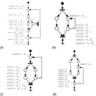
Fig. 5 shows several representative workflow models with cycles.
(c) (d)
Fig. 5. Several representative workflow models with cycles
(a): lcond(1,1)=B|bA|a, and wc(ea,1)=(B|bA|a)(B|bA|a)(B|bA|a), when ba is true, lcond(1,1) and wc(ea,1) are true at the same time. This means the workflow ends while the cycle is not terminated. The item 4) of Theorem 2 is not met. Therefore, the workflow model in (a) is not correct.
(b), (c) and (d) indicate three kinds of situations related to the concurrency. For these situations, four items 1), 2), 4) and 5) of Theorem 2 are met and item 3) of Theorem 2 should be checked.
The node 6 in (b) is an andJoin-type node and its whole-condition is wc(6,1) = T A|a. = a. Since the node locates outside the cycle, when lcond(3,1) = a is false, whether wc1(6,1) and wc2(6,1) are logically equivalent should be checked, Since [lcond(3,1) F] [wc1(6,1) wc2(6,1)] is true. So workflow model (b) is correct.
The node 7 in (c) has whole-condition wc(7,1) = A|a A|a. Because the node locates outside the cycle, when lcond(1,1) = a is false, whether wc1(7,1) = A|a and wc2(7,1) = A|a are logically equivalent should be checked. Since [lcond(1,1) F] [wc1(7,1) wc2(7,1)] is false, the workflow model (c) is not correct.
The node 7 in (d) has whole-condition wc(7,1) = T A|a. Because it locates inside the cycle, when lcond(4,1) = a is true, whether wc1(7,1) = T and wc2(7,1) = A|a are logically equivalent should be checked. Since formula [lcond(4,1) T] [wc1(7,1) wc2(7,1)] is true, the workflow model (d) is correct.
5.3. Discussion of Several Significant Technical Issues
The aim of this research is to build a unified software re-engineering approach to recovering business process from the existing system for the development of workflow oriented Information System. While the case study and the examples have shown the success of this research, several significant technical issues need to be further addressed.
Why is the proposed precondition-based workflow model suitable for software re-engineering?
For a large-scale complicated business process, it is rather hard for an analyser to have a complete concept of the system to describe the complex work procedures of the whole business. Facing a practical business process, it is easier to analyse each activity and its preconditions, and in turn to construct a reasonable workflow process diagram in a “bottom-up” way. This simplicity of the model makes it very suitable for software re-engineering. Especially, the model is applicable to optimisation and verification by introducing the concept of whole-condition, which is easily and efficiently implementable.
What is the relationship between the source code and the proposed precondition-based workflow model?
The main goal of the method is to be able to recover consistent and validated workflow models corresponding to the legacy code. Source code is at the lowest level. The workflow model is the business process concern at the higher level. Abstraction techniques have to be used to produce high level models/views from low level source code. Program transformation can be used as a pre-process of this abstraction process. Since the proposed workflow model has the similar control flow structure of the source code, the gap between the code and the model is easy to be bridged.
Which kinds of incorrectness can be verified in the precondition-based workflow model?
The verification of the proposed precondition-based workflow model method remains the features of the known analysis methods, i.e. three soundness properties: no deadlock (liveness), no wrong synchronisation and no infinite loop (non-termination). Particularly, the precondition of an activity consists of conditions with relative data, which makes it possible to analyse the impact of data on workflow correctness.
What is the automation degree of the proposed approach?
Since the abstraction process is knowledge-based, although a transformation tool can be developed to support this process, human intervention is still essential to complete the final transformation. For example, the determination of the granularity of an activity is granted to a software engineer. The software engineer is to simplify the extracted control flow diagram by replacing the code inside the diagram with more human readable expressions and activities. Since the gap between the control flow diagram and the precondition-based workflow model is very small, most jobs are quite direct and simple.
6.
Conclusion
This research proposes a unified software re-engineering approach from a business process perspective. A precondition-based workflow extraction method is developed to elicit the business processes from existing systems. Several reverse engineering techniques and tools have been employed. The fact that human interventions are still required indicates that it is only semi-automatic. The initial results underline the feasibility of the proposed approach. Concretely, the key contributions of this research are as follows:
New Workflow Model: The precondition-based workflow model is formally defined in this research. The simplicity and formality of the precondition-based workflow model make it very suitable for software re-engineering.
Precondition-based Method for Workflow Modelling and Verification: The correctness of the workflow model is formally defined. The concept of the whole-condition of an activity is proposed to translate the verification of the prewhole-condition- precondition-based workflow model into the problem of predicate determination.
Unified Approach: The proposed approach in this paper starts with understanding the source code of the system. A code abstraction algorithm is designed to filter out the non-business-logic related code from the source code. The proposed re-engineering method utilises the re-engineered control flow to build the precondition-based workflow model and ends with the desired reengineered workflow oriented system.
work is to link the precondition-based workflow model to standards, i.e. BPEL and BPMN, for modelling the workflows, which would be an important contribution.
References
1. Aalst, W.: Petri-net-based Workflow Management Software. In Proceeding of the NFS Workshop on Workflow and Business Process Automation in Information System. Georgia, 114-8. (1996)
2. Aalst, W.: The Application of Petri Nets to Workflow Management. Journal of Circuits, Systems, and Computers, 8(1), 21-66. (1998)
3. Aalst, W.: Workflow Verification: Finding Control-flow Errors Using Petri-net-based Techniques. In Proceeding of the Business Process Management, Models, Techniques, and Empirical Studies. London, 161-83. (2000)
4. Aalst, W., Weijters, T., and Maruster, L.: Workflow Mining: Discovering Process Models from Event Logs. IEEE Transactions on Knowledge and Data Engineering, 16(9), 1128-42. (2004)
5. Bae, J., Bae, H., Kang, S., and Kim, Y.: Automatic Control of Workflow Processes Using ECA Rules. IEEE Transaction on Knowledge and Data Engineering, 16(8), 1010-23. (2004) 6. Baeten, J.C.M. and Basten, T.: Partial-order Process Algebra (and its Relation to Petri
Nets). In Handbook of Process Algebra: Elsevier Science, Amsterdam, 769-872. (2001) 7. Bi, H. and Zhao, J.: Applying Propositional Logic to Workflow Verification. Information
Technology and Management, 5(3), 293-318. (2004)
8. Canfora, G., Cimitile, A., and Carlini, U.: A Logic-Based Approach to Reverse Engineering Tools Production. IEEE Transactions on Software Engineering, 18(12), 1053-64. (1992) 9. Choi, Y. and Zhao, J.: Decomposition-based Verification of Cyclic Workflows. In
Automated Technology for Verification and Analysis, Lecture Notes in Computer Science Volume 3707: Springer Berlin / Heidelberg, 84-98. (2005)
10. Cimitile, A. and Carlini, U.: Reverse Engineering: Algorithms for Program Graph Production. Software: Practice and Experience, 21(5), 519-37. (1991)
11. Clarke, E.M. and Wing, J.M.: Formal Methods: State of the Art and Future Directions. ACM Computing Surveys, 28(4), 626-43. (1996)
12. Davenport, T.: Process Innovation: Reengineering Work Through Information Technology: Harvard Business School Press, (1993)
13. Elsawy, O.: Redesigning Enterprise Processes for E-Business: McGraw-Hill Inc., (2001) 14. Fan, Y.: Fundamentals of Workflow Management Technology: Tsinghua University
Press/Springer-Verlag, (2001)
15. Foo, D., Guo, J., and Zou, Y.: Verifying Business Processes Extracted from E-Commerce Systems Using Dynamic Analysis. In Proceeding of the 3rd International Workshop on Program Comprehension through Dynamic Analysis. Vancouver, BC, Canada, 43-8. (2007) 16. Guo, J., Foo, K., Barbour, L., and Zou, Y.: A Business Process Explorer: Recovering
Business Processes from Business Applications. In Proceeding of the 30th International Conference on Software Engineering. Leipzig, Germany, 871-4. (2008)
17. Hammer, M. and Champy, J.: Reengineering the Corporation: A Manifesto for Business Revolution: Harper Business, (1994)
19. Hung, M. and Zou, Y.: Recovering Workflows from Multi Tiered E-commerce Systems. In Proceeding of the 15th IEEE International Conference on Program Comprehension. Alberta, Canada, 198-207. (2007)
20. Jacobson, I., Booch, G., and Rumbaugh, J.: The Unified Software Development Process: Addison Wesley, (1999)
21. Kappel, G., Rausch-Schott, S., and Retschitzegger, W.: Coordination in Workflow Management Systems - a Rule-based Approach. In Proceeding of the Coordination Technology for Collaborative Applications - Organizations, Processes, and Agents [ASIAN 1996 Workshop], 99-120. (1998)
22. Kiepuszewski, B., Hofstede, A., and Bussler, C.: On Structured Workflow Modelling. In Proceeding of the 12th International Conference on Advanced Information Systems Engineering. London, 431-45. (2000)
23. Koehler, J., Tirenni, G., and Kumaran, S.: From Business Process Model to Consistent Implementation: A Case for Formal Verification Methods. In Proceeding of the 6th IEEE International Enterprise Distributed Object Computing Conference. Lausanne, Switzerland, 96-106. (2002)
24. Liu, D., Wang, J., Chan, S.C.F., Sun, J., and Zhang, L.: Modeling Workflow Processes with Colored Petri Nets. Computers in Industry, 49(3), 267-81. (2002)
25. Liu, X. Abstraction: A Notation for Reverse Engineering. PhD Thesis, De Montfort University, England, (1999)
26. Marjanovic, O. and Orlowska, M.E.: On Modelling and Verification of Temporal Constraints in Production Workflows. Knowledge and Information Systems, 1(2), 157-92. (1999)
27. Mukherjee, S., Davulcu, H., Kifer, M., Senkul, P., and Yang, G.: Logic Based Approaches to Workflow Modeling and Verification. In Logics for Emerging Applications of Databases: Springer Verlag, (2003)
28. Müller, R., Greiner, U., and Rahm, E.: Agent work: A Workflow System Supporting Rule-based Workflow Adaptation. Data & Knowledge Engineering, 51(2), 223-56. (2004) 29. OASIS: Web Services Business Process Execution Language Version 2.0. OASIS Standard,
(11 April 2007)
30. OMG: Business Process Modeling Notation, V2.0. OMG Document: formal/2011-01-03, (Jan 2011)
31. Sadiq, W. and Orlowska, M.E.: Analyzing Process Models Using Graph Reduction Techniques. Information Systems, 25(2), 117-34. (2000)
32. Salimifard, K. and Wright, M.: Petri Net-based Modelling of Workflow Systems: An Overview. European Journal of Operational Research, 134(3), 664-76. (2001)
33. Sneed, H.: Extracting Business Logic from Existing COBOL Programs as a Basis for Redevelopment. In Proceeding of the 9th International Workshop on Program Comprehension. Toronto, Canada, 167-75. (2001)
34. Suenbuel, A. and Shan, M.: Towards Enterprise Archeology: Extracting Business Processes from Runtime Event Data. In Proceeding of the 6th IEEE International Conference on Data Mining. Hong Kong, 468-73. (2006)
35. Turner, C., Tiwari, A., and Mehnen, J.: A Genetic Programming Approach to Business Process Mining. In Proceeding of the 10th Annual Conference on Genetic and Evolutionary Computation. Atlanta, Georgia, USA, 1307-14. (2008)
36. Wang, Y. and Fan, Y.: Using Temporal Logics for Modeling and Analysis of Workflows. In Proceeding of the E-Commerce Technology for Dynamic E-Business, IEEE International Conference. Beijing, 169-74. (2004)
38. WfMC: Workflow Process Definition Interface-XML Process Definition Language. Workflow Management Coalition Workflow Standard, WFMCTC-1025, Version 2.2 (August 2012)
39. White, S.A., Miers, D., and Fischer, L.: BPMN Modelling and Reference Guide. Future Strategies Inc., (August 2008)
40. Wong, P. and Gibbons, J.: A Process-algebraic Approach to Workflow Specification and Refinement. In Software Composition: Springer Berlin / Heidelberg, 51-65. (2007)
41. Xiao, Z., Qi, C., and Huang, Q.: Verification and Reduction of Cyclic Structure in Workflow Model. In Proceeding of the 4th International Conference on Machine Learning and Cybernetics. Guangzhou, 1487-92. (2005)
42. Xu, F. and Yu, Z.: A Workflow Verification Method Based on Calculus. In Proceeding of the First Joint IEEE/IFIP Symposium on Theoretical Aspects of Software Engineering, 188-96. (2007)
43. Yang, H. and Ward, M.: Successful Evolution of Software Systems: Artech House, Inc., (2003)
44. Zou, Y. and Hung, M.: An Approach for Extracting Workflows from E-Commerce Applications. In Proceeding of the 14th IEEE International Conference on Program Comprehension. Athens, Greece, 127-36. (2006)
45. Zou, Y., Lau, T., Kontogiannis, K., Tong, T., and McKegney, R.: Model-Driven Business Process Recovery. In Proceeding of the 11th Working Conference on Reverse Engineering. Delft, Netherlands, 224-33. (2004)
Feng Chen was awarded his BSc, Mphil and PhD at Nankai University, Dalian University of Technology and De Montfort University in 1991, 1994 and 2007. As research outputs, he has published over 30 research papers in the area of software evolution and distributed computing.
Da Tang was awarded his BSc and Mphil at Dalian University of Technology in 1982 and 1985. He is currently an associate professor at Dalian University of Technology. His research interests include software engineering, workflow system, system modelling and verification.
Mohammed Alawairdhi obtained his BSc, MSc from King Saud University and California State University. He earned his Ph.D. degree in Computer Science from De Montfort University in 2009. He is currently working as an assistant professor in the college of Computer and Information Sciences, Al - Imam Muhammad ibn Saud Islamic University. He is also acting as the dean of the Computing and Informatics College in the Saudi Electronic University. His research interests include software engineering, ubiquitous computing, business process re-engineering and human computer interaction.