31
Simulation And Analysis Of Solar Powered
Brushless DC Motor
Abhilash Nilkanth Jadhav, Dr. V. A. Kulkarni (Deodhar)
Abstract: In this work, we have to design a solar photovoltaic as a source of renewable energy where the conventional generation is not convenient. The main aim of this research paper deals with developing a PV module connected brushless dc motor using maximum power point tracking algorithm. P and O algorithm is one of the simplest and effective methods of MPPT. In this method, maximum power is extracted from the solar module. Here in this work investigate the performance of solar power fed Brushless DC motor. The system model and interleaved boost converter are providing the reduce ripple content, switching loss and also promote the efficiency of the system. The speed controls of the BLDC motor are tested under the load condition. The model is designed in MATLAB simulation to ensure its working condition and also check the behavior of Interleaved boost converter.
Index Terms: Maximum Power Point Tracking (P and O Algorithm), MPPT Controller, Solar PV System, Interleaved Boost Converter, BLDC Controller, Brushless DC Motor
—————————— ——————————
1.
INTRODUCTION
The fossil fuel which is mostly considered as the main source of power and it should be exhausted in the next few years, so we need to generate alternative power from a non-renewable energy source. In recent years many research works have been done on the electrical application of PV energy as an alternative energy source of non-renewable energy source. Today the PV energy plays an important role in the whole world and they have various range of application like solar power used in the space program for satellite, electrical power generation [1]. Also rapid increment in demand of electricity and change in the environment condition due to a high amount of use fossil fuel energy such as global warming so need cheaper and substance having fewer carbon emissions so the huge effort has been given by the researcher to grow up the new technology for energy resource to its increased in a few years. That is why the algorithm of maximum power point tracking has been developed [2]. PV array does not have any rotating part in the system also there is no noise production also maintenances should below. In the PV system direct conversion of solar energy into electrical energy, no of a solar cell are connected together to form a solar array or solar module but the drawback of PV system is installation cost is high also efficiency is low of PV system so this drawback is overcome by maximum power point tracking. In this system, the interleaved boost converter is used. IBC has various advantages like low ripple content, efficiency it should high also switching loss will be low. high power application IBC is used. In this work, the solar PV system is used to drive BLDC motor because the relevance of BLDC motor has been increased day by day in industrial sector of the whole world [3]. Solar is one of the alternative energy sources since the overall cost of required for implementing is higher. They are mostly employed for high power applications.[4]
2
P AND O ALGORITHM
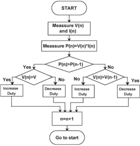
Among all MPPT method, perturb and observe is the technique which is used mostly to extract the maximum power from the solar PV system. in this technique, the value of generated power from the solar PV module is calculated and compared with the previous value of power which is stored in a memory of an algorithm, which gives the difference in the value of the power i.e. Present power- past power(dP). if the value of(dP) is higher than zero or if this perturbation leads to an improvement in the array power, so this perturbation condition is going continue in the same direction otherwise it should move in a reverse direction. perturb and observe was the simplest method in MPPT
Fig. 1. P and O Algorithm
the important advantages of p and o technique are their good skill to handle most challenging climate scenarios like partial shading, changes in irradiance and Exhibition of convergence towards the maximum power point is very faster. However and o technique suffers from three drawbacks. First one is P&O ————————————————
Abhilash Nilkanth Jadhav PG Student Department of Electrical Engineering, Government Engineering College Aurangabad, India 431005.
Dr. V.A. Kulkarni (Deodhar) Associate professor e Department of Electrical Engineering, Government Engineering College Aurangabad, India 431005
technique is oscillate near to peak point due to the behavior of technique. second, the p and O is fail to track MPP when suddenly change in irradiance with time. once the tracking direction is incorrect, the technique becomes confused and its go away from the MPP.[5] The third one is that P and O method will not capable of track maximum power under partial shading condition. Suppose the current power of solar module is on the left side of MPP then changes in a duty cycle of DC-DC converter so then cause of this perturbation is a change in the voltage and current of module. In p and o technique current power and previous power difference are positive as MPP is on the left side and the duty cycle of the converter is change till these differences have become zero.[6]
3
SOLAR
PHOTOVOLTAIC
SYSTEM
A solar cell is that convert the light energy into electrical energy on photovoltaic effect. It is a P-N junction semiconductor junction Figure 1. shows the circuit diagram of the solar cell. In which is diode is parallel in connected with source current for to developed solar PV cell. The solar panel is used to generate DC power from solar energy. In which there is a P-N junction
Fig. 2. Solar Photovoltaic System
Fig. 2. Solar Cell
a semiconductor is used for power generation because when solar ray falls on the solar panel, dc power will be produced and these powers linearly vary with solar irradiance. If the solar cell connected in series, then the voltage increased or if they should connect in parallel then output current is increased.
* (
) +
Where above equation is the current of PV panel; is no. of cell connected in series, is phase current of the solar panel, is the reverse saturation current of cell, 𝑞 is electron charge; 𝑘 is a Boltzmann ’s constant, is the no. of cell connected in series, 𝑣 is voltage of solar panel, 𝐴 is the ideality factor of the P_N junction and have ranged from 1 to 5. A group of PV cell forms a PV module and these modules interconnect to each other in the series/parallel form an array.[7]
Table 1. Specification of PV Panel
Parameters Measurement
Open circuit voltage (Voc) 38.5 V Max. power Current 8.46 A Number of series cells 60 Max. Power Voltage 31.5 Short Circuit Current (Isc) 9.13 A
INTERLEAVED BOOST CONVERTER
Fig. 3. Interleaved Boost converter
DC-DC converter is play a huge role in the form of various topology in various Electrical application. Interleaved means connect two or more circuit in parallels, so IBC is there is two or more boost converter connected in parallel and operated by2𝜋⁄ radians or same phase shift among switches and duty cycle should be same This type of Dc-Dc converter have many advantages such as switching loss low, minimum current, and voltage ripples and efficacy of IBC it should be high as compared with other conventional boost converters. In IBC the total no of power is divided into no. of converter connected in parallel [8].
5
BRUSHLESS
DC
MOTOR
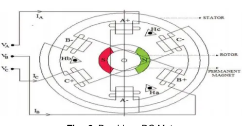
Fig. 3. Brushless DC Motor
33 which is used produced Ac current to drive each phase of
BLDC motor with the help of BLDC motor Controller. Hall sensor is used to measure the actual position of rotor. It should be most important parameter in speed control of motor in closed loop speed control but due to hall sensor the cost of system is increased [9].
TABLE. 2 BLDC motor parameters
Motor rating 1.1 HP
Voltage 250 V
Pole pairs 4
Stator phase resistance 3.07Ω Stator Phase Inductance 6.57 mH
Speed 2700
Inertia 1.8
Rated current 5.60 A
Peak Current 14.27 A
Rated Torque 3Nm
6
SYSTEM
DEVELOPMENT
Fig. 4. Implementations block diagram of developed System
The figure shows the Implementation block diagram of the system in which consist PV array, dc to dc converter, VSI inverter, MPPT controller and BLDC motor also to ensure the behavior and operation of the motor, Controller i. e. BLDC motor controller. In the above figure the PV cell connected in series or parallel to form a PV module or PV array, which is used to absorb the solar energy from the sun it converts into electrical energy by photovoltaic effect [10]. Generated electrical energy is given to the IBC which is replaced to the conventional converter. Interleaved boost converter is used to reduced stress on switches and input and output ripple in the circuit For maximum power is exact from the array one algorithm is implemented in this system the name of the algorithm is P and O algorithm in which power comes from PV module save in the memory of system so in another step newly power comes from solar module is compared with previous power value which is already stored in the memory. If the previous value is higher than the current power value so the duty cycle of IBC is changing to get the maximum power. Then the output of IBC is given to the Inverter to get constant output power and consequently constant output torque to drive the BLDC motor by switching the stator winding of motor in sequence. The motor controller is used to sense the position of rotor and speed of the motor from a hall effect sensor and
generate the switching signal for the three-phase inverter to an electronic commutation of motor. In the closed-loop speed control technique, the actual speed is measured and it should be compared with reference speed to find speed error and this difference is provided to PI controller to reduce the speed by changing the switching signal of the inverter.[11]
7
SIMULATION
MODEL
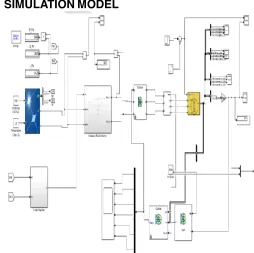
Fig. 5. MATLAB Simulation of Developed System
In the above figure, we can see that the complete simulation diagram of solar power fed brushless dc motor. The maximum power is transfer from solar system to BLDC Motor with the help of MPPT Algorithm. In the simulation model, the BLDC motor used to drive the specific load Application.
8
SIMULATION
RESULTS
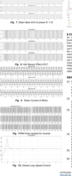
Simulation result of the above system as shown in the below figure. In which we can see the complete behavior of BLDC Motor and ensure the performance of the parameter which is used to developed above system.
Fig. 7. Stator Back Emf of phase R, Y, B
Fig. 8. Hall Sensor Effect A B C
Fig. 9. Stator Current of Motor
Fig. PWM Pulse applied for Inverter
Fig. 10. Closed Loop Speed Control
Fig. 11. Speed Vs Torque Characteristics
9 CONCLUSION
As we see modeled and simulated the solar power fed brushless DC motor. In which we can extract maximum power from a solar array with the help of P and O Algorithm. Interleaved boost converter is used in the system so that we can found that the IBC was helped reduced ripple content from the output as well as input side also it can reduce stress on switches. IBC suitable converter for high power renewable energy source. BLDC motor driven by solar energy and hence can be used in solar water pumping, E-BIKE also compressor. Closed loop Speed control Inverter fed BLDC Motor using PWM we can discuss in this paper. A feedback signal from motor indicates the speed and position of the motor which is utilized to generate the switching signal for the inverter.
REFERENCES
[1] Radak Blange Chitralekha Mahanta Anup Kumar Gogoi “ MPPT of Solar Photovoltaic Cell Using Perturb & Observe and fuzzy Logic controller Algorithm for Buck-Boost DC-DC Converter ” Dept. of Electronics & Electrical Engineering Indian Institute of Technology Guwahati, Assam, India. 2015 IEEE
[2] . Shamsun Nahar and M. Basir Uddin. ”Analysis the performance of interleaved boost converter ” Dept of electrical and electronic engineering, Dhaka University of Engineering& Technology(DUET) Gazipur, Bangladesh [3] Ashwin Chandwani, Abhay Kothari Department of
Electrical Engineering Institute of Technology, Nirma University Ahmedabad, India and Department of Electrical Engineering Institute of Technology, Nirma University Ahmedabad. India “ Design, Simulation and Implementation of Maximum Power Point Tracking (MPPT) for Solar based Renewable Systems ” 2016 International Conference on Electrical Power and Energy Systems (ICEPES).
[4] Santanu Mondal, Abhirup Nandi, Indranil Mallick, Chirantan Ghosh, Alapan Giri Department of Applied Electronics and Instrumentation Techno India Salt Lake Kolkata, India. “Performance Evaluation of Brushless DC Motor Drive for Three Different Types of MOSFET BasedDC-DC Converters ” DevIC March 2017.
[5] D. K. Sharma ,G. Purohit Advanced perturbation and observation(P&O) based maximum power point tracking (MPPT)of a solar photo-Voltaic System.
35 & Communication Technology (RTEICT), May 19-20,
2017, India.
[7] Jubaer Ahmed , Member, IEEE and Zainal Salam , Member, IEEE “An Enhanced Adaptive P&O MPPT for Fast and Efficient Tracking Under Varying Environmental Conditions ” IEEE.
[8] Shamsun Nahar and M. Bashir Uddin, Dept. of Electrical and Electronics Engineering Dhaka University of Engineering & Technology Gazipur, Banglashesh “ Analysis the performance of interleaved boost converter” 4th ICEEICT
[9] M.Poovizhi M.Senthil Kumaran P.Ragul L.Irene Priyadarshini “Investigation of mathematical modelling of brushless dc motor(BLDC) drives by using matlab-simulink ”IEEE 2017
[10] Abhilash Nilkanth Jadhav1 Dr. V. A. Kulkarni2 1,2 “ MPPT Techniques for PV Connected BLDC Motor Drives” (IJSRD/Vol. 7/Issue 03/2019/355).