Smart Car System Implemented by PSoC
Ashwini Lokare Dipika Thakur
B.E. (Pursing) B.E. (Pursing)
Department of Electronics Engineering Department of Electronics Engineering Mankhurd, Mumbai, India Chunnabhatti, Mumbai, India
Priyanka Gharat Rakhi Walimbe
B.E. (Pursing) B.E. (Pursing)
Department of Electronics Engineering Department of Electronics Engineering Bandra, Mumbai, India Thane, Thane, India
Mrs. Leena Govekar
Professor
Department of Electronics Engineering
Padmabhushan Vasantdada Patil Pratishthan’s College of Engineering
Abstract
This paper discusses design of smart car system which is implemented by PSoC. Main aim of this paper is to design an electronic device which is used for SOS message to detect accident situation and also used for engine locking which is implemented by PSoC. The paper includes hardware part which comprises of GSM, 16x2 LCD, PSOC KIT, USB-TTL and software part is used for interfacing all required modules.
Keywords: GSM Module, PSoC Kit, Engine Locking, Sos Message, Smart System
________________________________________________________________________________________________________
I.
INTRODUCTION
The nature of human being is to lead his life in most comfortable way. Our paper presents an idea of such system, which is most compact and is portable so to land it at any place of vehicle. However, such techniques are being implemented in many other conventional means but, due to the advent of PSoC(Programmable system on chip).The systems are being smaller and smarter. A SMART CAR SYSTEM is an electronic device installed in a vehicle to enable third party to detect the accident situation as well as monitor additional vehicle characteristics .Our system aims to effectively use a cellular communication component to establish a two way communication protocol between the user, and a central monitoring unit. We intend to use the GSM modem as a way of communication via SMS. The microcontroller is the heart of the system which in built in PSoC is controls the functioning of GSM communication unit for sending the correct SMS depending upon the current status of vehical. The add-on facility of Voice call is also available in the system. We are using psoc kit and for application we are using gsm module, which we are interfacing with psoc kit. This system easily implemented by using PSoC. It can be dynamically reconfigured by suitable programming at the run time. However, this programming can be done by using high level language such as „C‟ with which most of the hardware designers would be familiar. This makes „C‟ the natural language for system- on –chip.
Why we are using psoc kit??
Some of the important features of the PSoC are follows: Powerful Harvard architecture processor
Advanced peripherals Flexible on chip memory
II.
IMPLEMENTATION
Design: A.
Fig. 1: Block diagram of SMART CAR SYSTEM As shown in figure, basically there are four blocks. PSoC and GSM Module are interfaced with each other. GSM Module is used as way of communication via SMS. PSoC controls the functioning of GSM communication unit for
sending the correct SMS.
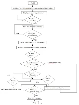
Software Design (Flowchart): B.
Algorithm: C.
1) Start
2) Define lookup table containing resistance values equivalent to temp range -40C to 125C. Set ref resistance to 10000. 3) Initialize all the components
4) Read channel 1 of mux to get reference voltage value Vref 5) Read channel 2 of mux to get thermistor voltage value Vtherm
6) Calculate thermistor resistance value by voltage divider rule (using Vref, Vtherm, Ref resistance values). 7) Compare thermistor resistance value with values in look up table to get equivalent temperature in integer. 8) Calculate accurate value after decimal points and add it in integer value to get total temperature in degree cen. 9) Receive char from UART, then transmit temperature in degree celcius.
10) Check the temperature value.
11) If temp rises in high quantity then send a S.O.S. Message. That is indication for the accident.
12) If “START SMS” is coming then make respective port pin high for glowing the LED. That is indication of “SMART ENGINE START”.
13) If “STOP SMS” is coming then make respective port pin low for turn off the LED. That is indication of “SMART ENGINE STOP”.
14) Stop
PSOC Kit (Hardware): D.
Fig. 3: Psoc kit
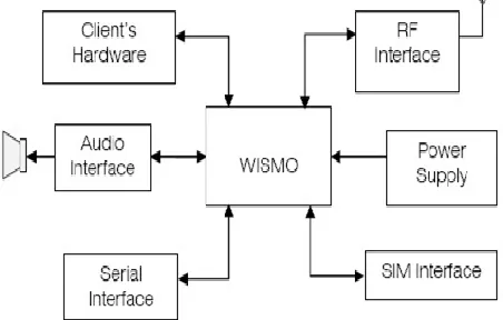
WISMO GSM Module: E.
Wavecom WISMO is designed as a plug-in module to fit in very small terminates and only some custom functions have to be added to make complete wireless communicate solution, as shown below. For WISMO to function properly, attention should be pay on the design of these extra elements. Figure external element integrated with WISMO.
Antenna Matching Circuit: F.
The goal of the matching circuit is to link the antenna(impedance ZA) to the receiver and transmitter access of the module(impedance ZL=50ohm real).
Fig. 5: Matching circuit
The matching circuit is composed by four elements implemented on the module connecting the “Antenna PAD” to the “Round PAD”(access to the receiver and the transmitter).Proper antenna matching is essential for WISMO module‟s performance and ESD(Electrostatic Discharge)compatibility. It is a must to choose a matching circuit to keep the antenna “DC” connected to the ground. Two topologies are proposed for matching circuit of WISMO Module is shown in below figure.
Fig. 6: Two topologies of matching circuit of WISMO Module
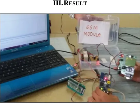
III.
RESULT
Fig. 7: Interfacing of GSM MODULE with PSOC
SMART CAR SYSTEM is still in development stages. The implementation of GSM interfacing, temperature sensor and led brinking programs are done. The work is going on software part for SOS message for engine start and stop application. The design of body is almost completed.
IV.
CONCLUSION
ACKNOWLEDGEMENT
We would like to acknowledge Prof. Mrs. Leena Govekar, M.E. Electronics from Padmabhushan Vasantdada Patil Pratishthan‟s College of Engineering, Mumbai for her guidance on this project.
REFERENCES
[1] Michael J.Point “EMBEDDED C” Pearson education limited 20 [2] www.engineersgarage.com/articles/gsm-gprs- modules [3] www.cypress.com
[4] The c programming language-Brian W. Kemighan,Dennis M. Ritchie [5] The 8051 Microcontroller and embedded systems-Mazidi Muhanmmad Ali [6] www.circuitstoday.com/interfacing-16x2-lcd- with-8051
[7] https://www.pantechsolutions.net [8] http://www.w3schools.com
[9] www.kathrein.pl/down/BasicAntenna.pdf