Nonlinear Transient Analysis and Parametric Design Studies of Complex
Engineering Structures Under Impact by a Large Airplane
A. Ibrahimbegovic1
1Ecole Normale Supérieure de Cachan, LMT-Cachan
61 avenue du president Wilson, 94235 Cachan, France e-mail: [email protected]
Abstract
In this work we address some of the present threats posed to engineering structures in putting them under extreme, transient loading conditions. The case which is studied in detail pertains to the terrorist attacks brought explosion and impact of large airplane on a massive structure, By using these case studies, we discuss the issues related to multi-scale modeling of inelastic damage mechanisms for massive structures, to time integration schemes in the presence multi-scale content in time brought by a particular nature of loading and finally to model reduction seeking to provide an efficient and sufficiently reliable basis for parametric studies employed within the framework of a design procedure. Several numerical simulations are presented in order to further illustrate the proposed approaches. Concluding remarks are stated regarding the current and future research in this domain.
Key words: complex structure, extreme conditions, transient response, impact, damage
1. Introduction
The present time challenge in fighting the man-made and natural hazards has brought about new issues in dealing with extreme transient conditions for engineering structures. The latter may concern on one side the permanently fixed structures, such as those built for energy source (e.g. nuclear power plants, dams) or the ones providing the storage of sensitive material (e.g. military installations) or the special structures found in transportation systems (e.g. bridges, tunnels), and on the other side the moving structures (such as trains, plains, ships or cars). A number of questions pertain to the problems of this kind from the viewpoint of structural integrity related to computer models of complex structures, a reliable representation of extreme loading conditions (which nowadays implies the need for solving a coupled problem) and uncertainty. In particular, we focus first and foremost on the first of those goals, which concerns the scale modeling of inelastic behavior of complex structures. The main advantage of the multi-scale approach is in its by far the greatest capabilities to provide the basis for constructing a sufficiently predictive model.
capabilities of the mechanics model will rise significantly, because we would need to know not only the usual information on 'extent' of cracking as defined by smeared models of plasticity or damage (see [19] or [18]), but we must also achieve a much more difficult goal of providing a sufficiently reliable information on crack spacing and opening, which is needed in order to compute the rate of leak. The model of this kind for predicting the detailed information in the fracture process of massive structure have been developed only recently, with applicability to metals [13] and concrete [2] or reinforced concrete [7]. The main characteristic of the models of this kind, presented in Section 2, concerns not only the original theoretical formulation, but also the finite element implementation.
The present terrorist danger has brought yet another extreme loading condition in terms of an impact of a massive structure by a large airplane, for which very few engineering structures have been designed to sustain. From the standpoint of nonlinear analysis, the main difficulty in such a problem pertains to a significant high frequency content typical of impact phenomena, as well as a quite likely presence of extensive structural damage. The first goal of the development we carried out pertains to the models for predicting inelastic behavior and damage for both airplane and massive structure. Yet another goal is to examine different impact scenarios in trying to quantify any potential reserve that might exist in the given design of an engineering structure for taking on higher level of risk. The complementary goal also of great importance pertains to providing the best way of reducing the negative impact of high-risk situation that cannot be avoided, by resorting to a more sound design procedure. One such procedure is illustrated in Section 3 in application to airplane impact problem.
Several representative numerical simulations are presented in Section 3 in order to further illustrate the performance of the nonlinear analysis and design procedures presented herein. Concluding remarks are stated in Section 4.
2. Multi-scale modeling of inelastic behavior of complex structures
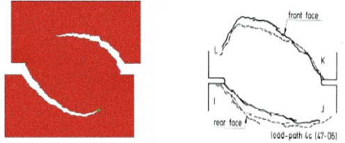
Fig. 1. Nooru-Mohamed experiment with non-proportional loading on double-notched concrete specimen: experimental vs. numerical results computed by discrete model.
Although it is not conceivable to use such a refined discrete model throughout a complex structure, this kind of experience has still taught us something useful for constructing the predictive models for inelastic behavior of structures. First, the theoretical formulation with an ever-increasing number of internal variables is not enough, and we also need to examine the issue of choosing the finite element interpolations. The latter can pertain to either incompatible mode enhancement of strain field [13] or an assumed stress field enhancement [21]. Second, it is clearly advantageous to separate complexities and create a model as a building bloc where each mechanism is associated its own criterion of inelastic behavior. One such example of the anisotropic concrete damage model capable of representing both volumetric dissipation and surface dissipation is discussed next.
The proposed model is constructed for dealing with massive structures. Indeed, massive structures often posses at the crack tip a fairly large "process zone" where damage develops, induced by the creation of micro-cracks, until the macro-crack forms due to the coalescence of some micro-cracks. The dissipation produced in the process-zone is far from being negligible with respect to the total dissipation and thus it has to be taken into account by exploiting a continuum damage model.
modifications of the solution strategy [15] or [20] due to the introduction of a displacement discontinuity.
The key point of the theoretical formulation is in reinterpretation of the strain field through introduction of a surface of displacement discontinuity, which will represent all localized dissipative mechanisms due to the apparition and development of localization zones. We further develop the modification introduced by this displacement discontinuity and present more precisely how to build each model associated to each dissipative mechanism. We consider a domain of influence Ώ which is split into two sub-domains by a surface of discontinuity Γ. The surface of discontinuity is characterized at each point by a unit normal vector, denoted as n, and a unit tangential vector, denoted as m. The discontinuous displacement field can then be written as:
( )
,( ) ( )
,(
( ) ( )
)
;( )
: 1 ;0 ;
t t t H ϕ H
+
Γ Γ −
⎧ ∈Ω
= + − = ⎨
∈Ω ⎩
x
u x u x u x x x
x (1)
where HΓ is the Heaviside function and φ is the correction function which reduces to zero the
discontinuity contribution outside of the domain of influence. The strain field can also be decomposed into a regular part and a singular part, the latter accompanying the Dirac-delta function δГ
( )
,t( )
,t sϕ( ) ( )
t(
( )
t)
sδ( )
Γ
= + ∇ + ⊗
ε x ε x x u u n x (2)
When considering a damage model, for which the strain-stress relation can be written by using the compliance tensor D
=
ε Dσ (3)
the compliance D must be decomposed into a regular and a singular part δΓ
= +
D D D (4)
The last two expressions ensure that the stress field will remain bounded and sufficiently smooth.
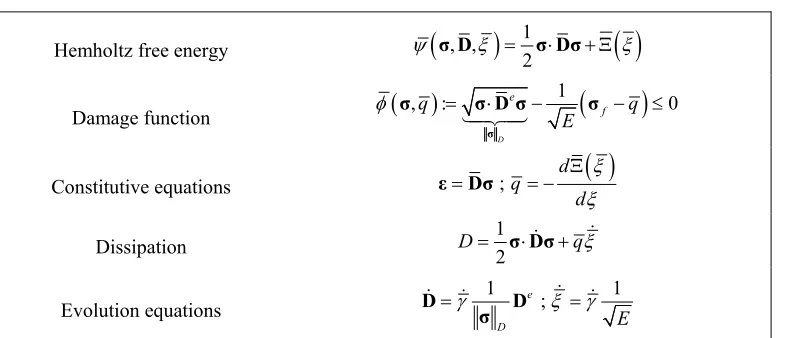
The same kind of additive decomposition is introduced for all internal variables, with any of them having both a regular and a singular part. Each part of the decomposition is associated with a damage dissipative mechanism, with the regular part for the continuum damage model and the singular one for the discrete damage model. We present subsequently the chosen formulation of the two damage models, the continuum one, associated to the bulk material, and the discrete one, associated to the localization zone. The continuum damage model, which takes into account the apparition and development of micro-cracks in the process zone with a quasi-\-homogeneous distribution, is considered as isotropic. The admissible stress domain is defined in terms of the damage function. The internal variables are the damage compliance denoted as D (with an initial value denoted as De equal to the inverse of the elasticity tensor De = C-1 and the
Hemholtz free energy ψ
(
σ, ,Dξ)
=12σ⋅Dσ+ Ξ( )
ξDamage function
(
)
(
)
1
, : 0
D e
f
q q
E
φ = ⋅ − − ≤
σ
σ σ Dσ σ
14243
Constitutive equations ε=Dσ;q= −dΞd
( )
ξξDissipation D=12σ⋅D&σ+qξ&
Evolution equations 1 e ; 1
D E
γ ξ γ
= =
D D
σ &
& & &
Table 1. Main ingredients of continuum damage model
Discrete damage model is proposed to account for the dissipative behavior in the localization zones, corresponding to macro-cracks for damage materials. It is constructed in an equivalent manner to the continuum damage model, except for multi-surface format of the proposed damage criterion [2], which is needed in order to control separately the normal and tangential components of the traction along the surface of discontinuity. This kind of damage surface coupling provides the proper influence of the normal interface pressure upon the tangential sliding resistance, as well as the reduction of cohesive force due to lateral sliding. The internal variables of the discrete damage model are the compliance of the interface, denoted as Q = n D n , and the variable associated to softening, denoted as ξ. In Table 2 below we summarize the main ingredients of this model.
Hemholtz free energy ψ
(
t QΓ, ,ξ)
=12t QtΓ⋅ Γ+ Ξ( )
ξDamage function
(
,)
:(
)
0n q f q
φ tΓ = ⋅ −t nΓ σ − ≤
(
,)
: q 0m s
f
q σ q
φ σ
σ
Γ Γ
⎛ ⎞
= ⋅ −⎜⎜ − ⎟⎟≤
⎝ ⎠
t t m
Constitutive equations ;q d
( )
d ξ ξ
Γ
Ξ
= = −
u Qt
Dissipation D=12t QtΓ⋅& Γ+qξ&
Evolution equations n m ; n q m
f
σ
γ γ ξ γ γ
σ
Γ Γ
= ⊗ + ⊗ = +
⋅ ⋅
Q n n m m
t n t m
& &
& & & &
Table 2. Main ingredients of discrete damage model
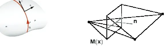
discontinuity is introduced by using the incompatible mode method [18]. A particular choice is made for the finite element interpolation according to (see Figure 2):
Fig. 2. Discontinuity of displacement across surface and its CST-based finite element approximation.
3
1
e
h e e e
a a a
Ω =
=
∑
+u N d M α (5)
where Nae is the standard shape function associated with the constant strain triangle and Me is a
discontinuous function presented in Figure 2. It is important to note that such a modified displacement interpolation has the same nodal value as the standard one, and hence da are still
the nodal displacement vectors. With such an approximation, the finite element interpolation of the strain field can be written as
3
1
; ;
e
h e e e e e e e
a a a a
a
Ω =
=
∑
+ = =ε B d Gα B LN G LM (6)
where L is the matrix representation of the differential (gradient) operator. The finite element interpolation of the virtual strain field can be constructed in the same manner
3
1
ˆ
e
s h e e e
a a a
Ω =
∇w =
∑
B w +Gβ (7)where wa and βe are, respectively, the virtual displacement nodal vector and element-wise
virtual displacement jump. We indicate in (7) that the incompatible mode strain-displacement matrix Ge is a modified form [18] of Ge in (7), which is needed in order to guarantee the
satisfaction of the patch-test; In general, these two matrices are different from one another. The virtual strain field will thus be decomposed into a regular and a singular part, and incompatible mode strain-displacement matrix can be written as:
ˆe e eδ e
Γ
= +
G G% G (8)
With those interpolations on hand, the discrete problem can be written as:
[ ]
(
)
[ ]
(
)
e[
]
int, int, ,
1
, ,
0 , , : ;
0 , , : ; 1,
el
e
e e
n
e e ext e e T
GNP e
e e e T e T
el GNP
dV
dV dV e n
= Ω Γ Ω Γ ⎡ ⎤ = = ⎣ ⎦− = = = − ∀ ∈
∫
∫
∫
r dα D f f f B σ
h dα D G% σ G t
A
(9)
For the frozen values of internal variables at Gauss numerical integration points DGNP, the
equilibrium equations, which takes a standard form for the finite element method and the second one is a local equilibrium equation written in each localized element. The latter can also be interpreted as the weak form of the traction continuity condition along the surface of discontinuity [2]. The time evolution of the discrete problem is computed by an implicit time integration scheme, accounting for the evolution of internal variables. The consistent linearization of this system leads to the set of linear algebraic equations, which can be written for time step n+1 and iteration (i):
( ) ( ) ( ) ( )
(
)
(
( ))
( ) ( )
(
)
( )(
( ) ( ))
( )[
]
, , , , ,
1 1 1 1 1
1 1
, , ,
1 ˆ 1 1 1 1 1 ; 1,
el el
n n
e i i e i e i ext int e i
n n n n n
e e
e i T i i i i e i e
n n n n n n e nel
+ + + + +
= =
+ + + + + +
Δ + Δ = −
+ Δ + + Δ = − ∀ ∈
K d F α f f
F k d H k α h
A A
(10)
where:
( ) ( ) ( ) ( )
( ) ( ) ( ) ( )
( ) e ( ) e
, , , , , ,
1 1 1 1 1
, , , , , ,
1 1 1 1
, , 1 1 ; ˆ ; ˆ ; e e e e e e
e i e T ed i e e i e T ed i e
n n n n n
e i e T ed i e e i e T ed i e
n n n n
i e T i e T
n n dV dV dV dV dA dA + + + + + Ω Ω + + + + Ω Ω Γ Γ + + Ω Ω = = = = ∂ ∂ = = ∂ ∂
∫
∫
∫
∫
∫
∫
K B C B H G C G
F B C G F B C G
t t
k G k G
d α
%
% (11)
By taking into account that the second equation holds independently in each localized element, for a given value of the displacement vector increment we can obtain the corresponding increment of the displacement jump on element-wise basis. We can then carry out the static condensation at the element level, reducing the system of equations to the standard form which is identical to the one obtained by isoparametric finite elements
( ) ( )
(
( ))
( ) ( ) ( ) ( ) ( )
(
( ) ( ))
, , ,
1 1 1 1
1 1
1
, , , , ,( ) , ,
1 1 1 1 1 1 1
ˆ
ˆ ˆ ˆ
el el
n n
e i i ext int e i
n n n n
e e
e i e i e i e i e i e i T i
n n n n n n n
+ + + + = = − + + + + + + + ⎡ ⎤ Δ = − ⎣ ⎦ ⎡ ⎤ = − ⎣ + ⎦ +
K d f f
K K F H k F k
A A
(12)
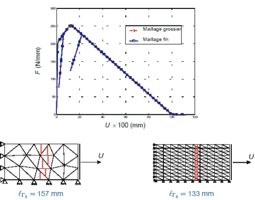
We therefore obtain an enhanced performance of the finite element approximation without any change of the global structure of the code. The proposed damage model, which considers interplay of both continuum and discrete dissipation mechanisms, produces mesh-invariant results for any sufficiently refined mesh; see Figure 3.
Fig. 3. Force-displacement diagram for simple tension test on a specimen with imperfection: mesh-invariant results are obtained for two different approximation of macro-crack with a coarse or a fine mesh, because two dissipative mechanisms always remain coupled and are
forced to store the total external energy input.
The predictive capabilities with respect to crack spacing and opening for this kind of model are illustrated in Figure 4, where we demonstrated the important role played by bond-slip element in redistributing more evenly the stress transfer mechanism along the steel bar, as well as an excellent correlation between the experimental and numerical results, even in the case of dispersion of slip resistance [7].
Fig. 4. Pull-out test for reinforced concrete beam and crack spacing: experimental results and numerical results (constant bond-slip with crack spacing of 15 cm and variable bond-slip resistance using the standard variation of 0.05 with crack spacing varying between 13 and 19
cm.
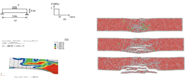
2. Multi-scale in time and load of short duration: Impact of airplane on massive structures In this section we present our recent work on trying to incorporate the significant advances in nonlinear analysis within the design procedure of a complex engineering structure under equally complex loading. The case in point is the impact by airplane on a massive structure, such as a nuclear power plant (see Figure 5) or military installations.
Fig. 5. Nuclear power plant: massive structure built to sustain airplane impact.
The traditional design procedures for this kind of problem are not applicable to complex structure and even less so to complex, non-proportional loading case (such as the one produced by frictional contact of the airplane with the structure). Namely, a number of empirical expressions, which have been proposed and used currently, are based on rather simplified interpretations of experimental results of projectile tests perforating different plate-like structures. There exists a very large dispersion in these experimental results on a single structural component and more importantly their lack of pertinence to complex structures, which makes them practically inapplicable to the case of complex structures under complex loading. Therefore, a novel approach to nonlinear analysis of this problem is sought, which is capable of taking into account the final goal of engineering design for such a structure.
Fig. 6. Hard vs. soft impact.
The main difficulty in dealing with this class of impact problems is related to the type of impact one should take into account; In that respect, we distinguish between the hard impact, where the projectile is much more stiff than the target, and the soft impact, where the target is at least as stiff as the projectile (see Figure 6). Another difficulty is related to a great diversity of damage modes to be accounted for, including perforation and spalling.
the local analysis results and which provides a much higher efficiency of the computations in the global phase, so that one can carry our all the parametric studied which are needed in the design phase (see Figure 7).
Fig. 7. Design procedure based on mesh transfer between local phase and global phase.
The local phase of the analysis is carried out first, by using a very refined model of a single component corresponding to the impacted zone. The analysis of this kind considers the finite element model of the projectile (of the finite element model of an airplane), which can account for the large plastic deformations developing at impact and frictional contact with potentially large frictional sliding. For that reason, an explicit, central difference scheme is used for such an analysis according to
(
)
(
)
2 1
int
1 , 1 1
1 1
ˆ , , ,...
2
n n n n
vp
n contact n n GNP
n n n n
t t
t
+
+ + +
+ +
= + Δ + Δ
⎡ ⎤
= − ⎣ ⎦
Δ
= + +
d d v a
Ma r f d ε D
v v a a
(13)
where d, v and a are, respectively, displacements, velocities and accelerations and M is the mass matrix, which is taken of a diagonal form in order to enhance the computation efficiency. We indicated in the last expression that the main source of nonlinearity, besides impact and frictional contact by the airplane with contact forces denoted as rcontact, are the plastic and
damage deformations of the impacted component of the structure, which are all contained in term fint.
For the purpose of structural design, we ought to provide a very reliable representation of the damage in the impacted structural component, where the latter is built of reinforced concrete. Several damage mechanism have to be represented: the first is concrete damage in tension leading to cracking, the second one is the damage in compression with the original feature that the concrete initially hardens due to compaction with an increase of stress until the ultimate value where the concrete will break, and the last one is the dependence of compressive and tensile strength of concrete with respect to the rate of deformation (see Figure 8). The fracture of concrete in tension is described by a criterion depending directly upon the principal values of tensile elastic strains in a quite similar manner as for the model presented in the previous section [4], including the modification for different fracture energies for cracking in tension and cracking in compression. The criterion for the concrete damage in compression is constructed as a modified form [8] of the Gurson plasticity criterion, defined with
(
*)
2 * 1(
(
*)
2)
1 2 3
2
3
, , 2 cosh 1 0
2
ij m
m m
J I
f q f q q f
φ σ σ
σ σ
⎛ ⎞
= + ⎜ ⎟− + ≤
where σij are the components of the nominal stress tensor, σm is the reference value of the stress
in the matrix, f* is the concrete porosity and q1, q2, q3 are the chosen coefficients. The graphic
illustration of this criterion for both compressive and tensile stress is provided in Figure 8.
Fig. 8. Constitutive model of concrete for dynamic analysis: dependence of compressive and tensile strength on rate of deformation, yield-damage criterion and hardening introduced by
compaction.
Porosity is made dependent on equivalent plastic deformation, and the same parameter defines the threshold for element erosion, defining the stage where the element is damaged to that extent that it ought to be completely removed from the mesh. The evolution equations for plastic deformation in compression and damage deformation in tension are chosen as rate dependent, in order to account for the effects of rate of deformation, which is quite pronounced for this class of problems (see Figure 8).
The numerical implementation of the proposed model is incorporated within the proposed computational framework in ( ). However, contrary to explicit scheme computations for the global momentum balance equations, the integration of the evolution equations for internal variables, such as plastic strains, damage compliance and hardening/softening variables, is carried out by an implicit scheme. The latter provides at each step the admissible values of stress with respect to the chosen criteria, and leads to a very robust numerical implementation. For more details on model numerical implementation we refer to [8].
Fig. 9. Experimental results of slab perforation obtained at Sandia US National Lab. And results of our numerical simulations.
by Sugano and co-workers. Following the test program, we simulate impact on the reinforced concrete slabs by different size missiles equivalent to aircraft engine. In particular, we performed simulations for Large size Equivalent and Deformable missile (LED), Medium size Equivalent and Deformable missile (MED) and Small size Equivalent Rigid missile (SER); See Figure 9 for details.
The missiles are used for impacting different concrete slabs (see also Figure 9, with a particular choice made for two of them as summarized in Table 3. In numerical simulations the missiles where modeled by using the shell finite element models, except for SER missile with the mesh of 3D solid elements. The concrete slabs are modeled with under-integrated 3D solid elements with the proposed constitutive model, and the reinforcement is modeled with truss-bar elastoplastic elements.
No. Missile
type Velocity(m/s) Slab thick. (m) Reinf. ratio Slab type Perfor. Spal. Penetr.
S10 SER 141 0.15 0.4 Small #1 No Yes Yes
L5 LED 214 1.60 0.4 Large #3 No Some Yes
Table 3.. Simulated impact tests - missile and slab characteristics and experimental results
The qualitative results observed in experiments are presented in Table 3; we note that penetration means that the missile penetrated the slab without having gone through it, perforation means that missile went through, scabbing means that the impact generated a scab on the rear face of the slab.
Very similar results are obtained in our numerical simulations and presented in Figure 13 for slabs S10 and L5, respectively. The computations where stopped when the velocity of the missile stopped decreasing, which implies that the missile was finally stopped by the concrete. We observed a fair amount of damage of a thin slab in this numerical simulation, not enough to allow for the missile penetration but only the spalling which occurs at the rear face. For the thick slab, the damage remains localized in the impact area with a large undamaged volume separating the damage on the front face and damage on the rear face. The latter implies the presence of only some small cracks. On the basis of results obtained in our numerical simulations, we can conclude that the proposed model is capable of providing a very good correlation with the tests.
Fig. 14. Numerical simulation of 3-point bending testing: continuum model with element erosion can remove completely damaged elements, and discrete model can also represent
spalling as well as the motion of any detached piece of specimen.
In the numerical simulation of this kind of test we can reproduce some or all of these results, depending upon the kind of model which we are using; See Figure 14. Our damage-plasticity continuum model is capable of predicting the extent of the damage zone associated with a large value of damage variable, or even eliminate all the elements that are extensively damaged by activating the erosion criterion. However, with such a continuum model we can eliminate but can no longer follow the motion of the pieces which are now detached from the structural component. For that reason, we have developed [14] a discrete model based on Vornoi cell representation of the specimen, where the cohesive forces between the adjacent cells are represented by geometrically exact Reissner beam model [12]. This particular feature of the beam model with its capability for representing overall large motion (accompanied by small strains) is crucial for the present application, where the detached piece is represented by several Vornoi cells with preserved cohesive forces; See Figure 14. A special attention is paid [6] to implementing the appropriate time-integration schemes capable of controlling the high frequency content of motion [11] and thus minimizing the risk of spurious stress oscillation introduced by brittle fracture.
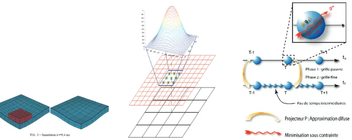
Fig. 15. Coarse and fine mesh representation of plate-like structural component and space-time field transfer between two meshes based on diffuse approximation.
The second simplification consists of replacing the true loading on impacted structural component which stems from time consuming computation of frictional contact and impact of the airplane with the equivalent nodal loading applied at the nodes of the coarse mesh of the structural component which is used in the global analysis phase. This task is very much like the construction of a phenomenological model of material obtained from a detailed representation of the material microstructure.
The problem of this kind belongs to the class of field transfer problems. The main difficulty we have to deal with herein concerns the best choice between two possible manners to accomplish this task. In order to fix these ideas we further consider a simple problem where a single structural component, a slab represented by a fine mesh of 3D solid elements, is impacted by a small plate (see Figure 15). This nonlinear impact problem is solved by central difference scheme by using typically small time steps that are imposed by the small size of the finite elements in the fine mesh. We well further seek to recover as close as possible the results of the nonlinear impact analysis on the coarse mesh by using again the central difference scheme, driven no longer with contact, but with an equivalent loading applied on the coarse mesh.
The first transfer problem concerns the space coordinates, or in other words, the transfer between the fine and the coarse mesh. The field transfer is done for any point of the coarse mesh, denoted as x, where we need the best possible coarse mesh representation of the results obtained on the fine mesh. The coarse mesh representation is constructed in accordance with moving least square approximation of the fine mesh transfer. More precisely, for the displacement component on the coarse mesh dicoarse (x) we assume that one can use the
projection which is based on the nodal values of the corresponding displacement component obtained in the neighborhood of x on the fine mesh, difine (xj)
( )
:(
( )
)
;( )
coarse fine fine
i i j j
d x = Π d x ∀ ∈x N x (15)
The projection of this kind should be in accordance with the moving least square approximation which is written as
[
]
( )
0
1
1 2 3
2
3
1 T T
coarse i
a a
d x x x
a a ⎡ ⎤ ⎢ ⎥ ⎢ ⎥
= =
⎢ ⎥ ⎢ ⎥ ⎢ ⎥ ⎣ ⎦
where a are the approximation parameters to be determined from the least square fit. The latter can formally be formulated as the following minimization problem
( ) ( )
(
)
( )
( )
( )
2
a
1
min ; ,
2
T fine
j j i j
j
J J W d
∈ ⎡ ⎤ = ⎢ − ⎥ ⎣ ⎦
∑
N xa a x x p x a x (17)
where W(x,xj) are the bell-shaped weighting functions (see Figure 15), which are chosen in
order to limit the influence of the points placed farther away from the point x as well as to provide a continuous approximation when moving across domain of influence of the neighboring nodes on the coarse mesh. The latter is true [24] only when taking more than a minimum of four points in the neighborhood xj € N(x), j=1,…,m ≤ 4, or otherwise the
weighting functions will play no role. The cost function in the minimization problem in (34) can also be stated in matrix notation as
( )
1 1 ,2 2
T T T fine fine T fine
J a = a PWP a a PWd− % + d% Wd% (18)
where the weighting factors, interpolation polynomial and fine mesh displacement values are stored as
(
)
(
)
( )
( )
( )
( )
1 1 1, ... 0 . .
... ... ... ; . ; .
0 ... , . .
T fine i T fine m fine T i m m
p x d x
W x x
W x x
d x p x ⎡ ⎤ ⎡ ⎤ ⎢ ⎥ ⎢ ⎥ ⎡ ⎤ ⎢ ⎥ ⎢ ⎥ ⎢ ⎥ ⎢ ⎥ ⎢ ⎥ =⎢ ⎥ =⎢ ⎥ = ⎢ ⎥ ⎢ ⎥ ⎢ ⎥ ⎢ ⎥ ⎣ ⎦ ⎢ ⎥ ⎢ ⎥ ⎢ ⎥ ⎣ ⎦ ⎣ ⎦
W P d% (19)
The Kuhn-Tucker optimality condition of this minimization problem leads to the optimal value of approximation parameters
1
a ⎡ T⎤− fine
= ⎣PWP ⎦ PWd% (20)
which defines completely the chosen approximation in (34).
Having clarified the field transfer in space between the fine and the coarse mesh, we now consider the transfer of evolution problem in time, where the time steps used on the selected coarse mesh are likely to be much bigger than those used previously on the fine mesh. The main difficulty in that respect pertains to two possible manners of performing such a field transfer. In order to further elaborate on this idea, we consider a single time step of the coarse mesh computation which corresponds to a number of small steps of the fine mesh; See Figure 15. One possible way for the field transfer is by first carrying out the computations on the fine mesh by using the central difference scheme in (31) and then use the projection (34) of such a result to the coarse mesh. This kind of field transfer can formally be written as
( )
(
( )
)
( )
(
( )
)
( )
( )
(
( )
)
( )
(
( )
)
1 1 1 1
1 1 1 , 1
: ; :
: ; :
coarse fine fine coarse fine fine
n n j n n j j
coarse fine fine coarse fine fine
n n j n contact n j
+ + + +
+ + + +
= Π = Π ∀ ∈
= Π = Π
d x d x v x v x x N x
a x a x f x r x (21)
where dn+1fine, vn+1fine and an+1fine are, respectively, the computed vectors of displacements,
velocities and acceleration at time t n+1, while rcontact,n+1 fine are nodal forces computed from
There is an alternative way to carry out the transfer, which implies the need for computations on the coarse mesh as well. Namely, we first start with the transfer of the results obtained on the fine mesh, and then follow up with the computation carried out on the coarse mesh. The latter can formally be written according to
( )
(
( )
)
(
( )
)
(
( )
)
( )
( )
(
( )
)
( )
( )
(
(
( )
)
( )
)
2 1 int1 1 1
1 1
ˆ ,...
2
coarse fine fine fine fine fine fine
n n j n j n j
coarse coarse
n n n
coarse coarse fine fine coarse
n n n j n
t t t + + + + + + = Π + Δ Π + Δ Π = − Δ = + Π +
d x d x v x a x
Ma x g x f d x
v x v x a x a x
(22)
From standpoint of computational efficiency, there is one crucial difference between computational procedure on fine and on coarse mesh: the former is driven by impact and frictional contact and the latter is driven by equivalent nodal loading gn+1. Such an equivalent
nodal loading is obtained as the solution of the minimization problem seeking to render the results of two field transfer procedures as close as possible
(
)
1 1 g min n n J + +g (23)
with the explicit form of the cost function defined as
(
)
( )
(
( )
)
(
)
(
( )
(
( )
)
)
{
( )
(
( )
)
(
)
(
( )
(
( )
)
)
( )
(
( )
)
(
)
(
( )
(
( )
)
)
}
1 1 1 1
1 1 1 1 1
1 1 1 1
1 2 coarse
T
coarse fine coarse fine
n n n n
T
coarse fine coarse fine
n n n n n
T
coarse fine coarse fine
n n n n
J dV + + + + + + + + + Ω + + + + − Π − Π + = − Π − Π + − Π − Π
∫
d x d x d x d x
g v x v x v x v x
a x a x a x a x
(24)
The dependence of such a cost function on the equivalent load vector on the coarse mesh gn+1 is
defined through (39).
In seeking to enforce further result correspondence of these two types of field transfer, we can also require that the work of the equivalent loads on the coarse mesh over any time step of the coarse mesh computations remains as close as possible to the work of contact forces on the fine mesh. The latter can formally be written as
(
)
1(
)
1 1 1
1
2 coarse 2
T coarse T T fine
n n
n n n n n contact
t t
C + W dV
+ + + Ω ⎧ ⎫ = ⎨ + − ⎬ ⎩ ⎭
∫
g g v g v (25)
where Wcontactfine is the work of contact forces which is computed on the fine mesh during the
same time step. One can thus modify the optimization problem in (41) by adding the last condition as the constraint
(
) (
)
(
)
(
)
1 1 1 1 1 1 1 1 1
g λ
min max , ; ,
n n n n n n n n n
L L J C
+ + + + + + + + +
= +
g λ g λ g λ g (26)
We have carried out the computations with these four methods for the impacted thick plate component in Figure 15. The results on representing the upper and lower bounds are obtained by carrying out the computations of the impact problem on the fine and on the coarse mesh, respectively. The first set of computations, performed for the case of the elastic plate (see Figure 16), have shown that all the methods can give fairly good results, since a reasonably good representation of the fundamental vibration modes is the only condition which should be fulfilled. The second computations with four methods are carried out for elastoplastic plate (see Figure 17). In this case, the fourth method clearly shows far superior results, which is the consequence of the highest level of consistency we impose for this kind of field transfer.
Fig. 16. Computed displacement and energy with fine and coarse mesh and four different projection methods - elastic case.
Fig. 17. Computed displacement and energy with fine and coarse mesh and four different projection methods - elastoplastic case.
3. Conclusions
We have shown that the proposed procedures for nonlinear inelastic analysis of complex structures have reached a fair level of reliability, where they can be used to supplement the time consuming and costly experimental procedure on structures. We have also shown how to reduce the amount of information coming from refined models used for nonlinear analysis of a particular structural component, in view of preparing the reduced model for parametric studies and a novel design procedure, which should verify the integrity of not only a single component but also of the whole structural assembly.
Current works deal with the development of computer models capable of providing additional information from the structural testing under heterogeneous stress field, and accounting for heterogeneities in material properties [15]. The model reduction procedures in dynamics, as those proposed earlier in [9], are also studied to be used in dynamics [22] and in earthquake engineering design [5]. Model and mesh adaptivity issues, where the choice between refined and coarse model is made, geared towards the ultimate load computation of a complex massive structures also belong to our current research activities of this kind [1], [3]. The procedures for optimal design of complex structures in presence of inelastic nonlinear behavior are also being developed [17]. Finally, we are currently seeking a deeper understanding of the physical aspects which would allow to construct the key ingredient of probabilistic description of inelastic nonlinear phenomena and thus feed the proposed computational procedure for probabilistic studies of nonlinear behavior of complex structures, presently available mostly for linear problems [23].
Acknowledgements:The research results summarized herein are obtained in several research projects carried out at LMT-Cachan, with participation of a couple of senior colleagues, Dr. Luc Davenne and Prof. Pierre Villon, and four of my former doctoral students at ENS-Cachan, Dr. Delphine Brancherie, Dr. Jean-Baptiste Colliat, Dr. Norberto Dominguez and Dr. Guillaume Herve. We would like to acknowledge the financial support of: the French Ministry of Research and CNRS under ACI 2159; French-Mexican Cooperation Program, CEA/DAM , CTTB and EDF/AMA.
References
[1] D. Brancherie, P. Villon, A. Ibrahimbegovic, A. Rassineux and P. Breitkopf, Transfer operator based on diffuse interpolation and energy conservation for damage materials, Proceedings 3rd MIT Conference in Computational Fluid and Solid Mechanics, (ed. K.J. Bathe), Elsevier, Amsterdam, Netherlands", 2005,
[2] D. Brancherie and A. Ibrahimbegovic, Macro-scale model of dissipative phenomena produced at micro-scale: theoretical formulation and numerical implementation, European J. Finite Elements, 13, 461-475, 2004.
[3] U. Bohinc, A. Ibrahimbegovic and B. Brank, Robust plate finite elements for adaptive modeling of structures, Congress of Slovenain Society of Mechanics", (ed. J. Korelc), Ljubljana, Slovenia, October, 2005,
[4] J-B. Colliat, A. Ibrahimbegovic and L. Davenne, Saint-Venant multi-surface plasticity model in strain space and in stress resultants, Engineering Computations, 41, 536-557, 2005,
[5] L. Davenne, F. Ragueneau, J. Mazars and A. Ibrahimbegovic, Efficient Approach to Earthquake Engineering Analysis, Computers and Structures, 81, 1223-1239, 2003. [6] Delaplace and A. Ibrahimbegovic, Time-integration schemes for dynamic fracture
[7] N. Dominguez, D. Brancherie, L. Davenne and A. Ibrahimbegovic, Prediction of crack pattern distribution in Reinforced Concrete by coupling a strong discontinuity model of concrete cracking and a bond-slip of reinforcement model, Engineering Computations, 41, 558-582, 2005.
[8] G. Herve, F. Gatuingt and A. Ibrahimbegovic, On numerical implementation of a coupled rate dependent damage-plasticity constitutive model for concrete in application to high-rate dynamics,, Engineering Computations, 22, 583-604, 2005. [9] A. Ibrahimbegovic, H.C. Chen, E.L. Wilson and R.L. Taylor, Ritz method for dynamic
analysis of large discrete linear systems with non-proportional damping, Earth. Eng. Struct. Dyn., 19, 877-889, 1990.
[10]A. Ibrahimbegovic and E.L. Wilson, Unified Computational Model for Static and Dynamic Frictional Contact Analysis, International Journal for Numerical Methods in Engineering, 34, 233-247, 1991.
[11]A. Ibrahimbegovic and S. Mamouri, Energy conserving/decaying implicit time-stepping scheme for nonlinear dynamics of three-dimensional beams undergoing finite rotation, Computer Methods in Applied Mechanics and Engineering, 191, 4241-4258, 2002.
[12]A. Ibrahimbegovic and R.L. Taylor, On the role of frame-invariance in structural mechanics models at finite rotations, Computer Methods in Applied Mechanics and Engineering, 191, 5159-5176, 2002.
[13]A. Ibrahimbegovic and D. Brancherie, Combined hardening and softening constitutive model of plasticity: precoursor to shear slip line failure, Computational Mechanics, 31, 88-100, 2003.
[14] A. Ibrahimbegovic and A. Delaplace, Microscale and mesoscale discrete models for dynamics fracture of structures built of brittle material, Computers and Structures, 81, 1255-1265, 2003.
[15]A. Ibrahimbegovic and D. Markovic, Strong coupling methods in multi-phase and multi-scale modeling of inelastic behavior of heterogeneous structures, Computer Methods in Applied Mechanics and Engineering, 192, 3089-3107, 2003.
[16]A. Ibrahimbegovic, D. Markovic and F. Gatuingt, Constitutive Model of Coupled Damage-Plasticity and Its Finite Element Implementation, European J. Finite Elements, 12, 381-405, 2003.
[17]A. Ibrahimbegovic, I. Gresovnik, D. Markovic, S. Melnyk and T. Rodic, Shape optimizatoin of two-phase inelastic material with microstructure, Engineering Computations, 22, 605-645, 2005.
[18]A. Ibrahimbegovic, Nonlinear solid mechanics : theoretical formulations and finite element solution procedure (in French), Hermes-Science – Lavoisier, Paris, 2006. [19]M. Kojic and K.J. Bathe, Inelastic Analysis of Solids and Structures, Springer, 2005. [20]D. Markovic and A. Ibrahimbegovic, On macro interface conditions for
micro-scale based FEM for inelastic behavior of heterogeneous materials, Computer Methods in Applied Mechanics and Engineering, 193, 5503-5523, 2004.
[21]D. Markovic and A. Ibrahimbegovic, Complementary energy based FE modeling of coupled elasto-plastic and damage behavoir for continuum microstructure computations, Computer Methods in Applied Mechanics and Engineering, 195, 5077-5093, 2006.
[22]D. Markovic, K-C. Park and A. Ibrahimbegovic, Reduction of substructural interface degrees-of-freedom in flexibility based component mode sythesis, International Journal for Numerical Methods in Engineering, 70, 163-180, 2007.
of Engineering Structures Under Extreme Conditions, (eds. A. Ibrahimbegovic and B. Brank), IOS Press, Amsterdam, Netherlands", 123-164