MODELLING AND SIMULATION OF AN INDUCTION MOTOR USING SOLAR PANEL
A R T I C L E I N F O
INTRODUCTION
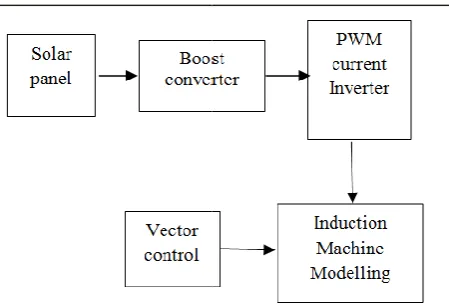
Solar panel is being employed around the world in most recent years. It is widely used in many applications. Using panels as the power source, to run an induction motor. A DC DC converter is considered as a dc equivalent to an AC transformer with a continuously variable turn ratio. Since output of the solar panel is very less, a boost converter is used to increase the voltage level. The boost regulator provides an output voltage which is greater than the input voltage. The input current of this regulator is continuous. It has low switching loss and has high efficiency. The PWM inverter is converts the dc voltage to the ac voltage and is implemente the modelling of an induction motor. The induction motor is modelled by Park’s Transformation. To generate the speed, PI control is implemented to control the speed.
Classical controllers (PI, PID) are widely used in industry while more advanced techniques of control, such as adaptive controllers are less used in industry. This is due to the fact that:
1. Classical controllers are simpler to implement and their algorithms are easier.
2. Parameter tuning of classical controllers is not a hard task for manipulators.
International Journal of Current Advanced Research
ISSN: O: 2319-6475, ISSN: P: 2319-6505,
Available Online at www.journalijcar.org
Volume 8; Issue 06 (C); June 2019; Page No.
DOI: http://dx.doi.org/10.24327/ijcar.2019
Copyright©2019 Aravindaraj. K. This is an open access article distributed under the Creative Commons Attribution License, which permits unrestricted use, distribution, and reproduction in any medium, provided the original work is properly cited.
Article History:
Received 12th March, 2019
Received in revised form 23rd
April, 2019
Accepted 7th May, 2019
Published online 28th June, 2019
Key words:
Solar panel, Boost converter, PWM inverter, Induction machine modelling.
*Corresponding author: Aravindaraj. K
PG Scholars, SRM University, India
MODELLING AND SIMULATION OF AN INDUCTION MOTOR USING SOLAR PANEL
Aravindaraj. K
PG Scholars, SRM University, India
A B S T R A C T
Solar panel is increasing employed in the industrial application. In this paper, the boost converter steps up the voltage produced by the solar panel to a voltage which is applied to the induction machine modelling. The inverter converts dc to ac by means of pulse width modulation (PWM) technique. Design of this paper is directly coupled to get the voltage from 72 solar cell panel, DC –DC Boost converter, full bridge pulse width modulation inverter, modelling of an induction motor is presented. The PI feedback controller is used to control the speed. The model was implemented using MATLAB with PWM inverter.
Solar panel is being employed around the world in most recent many applications. Using solar to run an induction motor. A DC-DC converter is considered as a dc equivalent to an AC transformer with a continuously variable turn ratio. Since output of the solar panel is very less, a boost converter is used ulator provides an output voltage which is greater than the input voltage. The input current of this regulator is continuous. It has low switching loss and has high efficiency. The PWM inverter is converts the dc voltage to the ac voltage and is implemented to the modelling of an induction motor. The induction motor is modelled by Park’s Transformation. To generate the speed, PI
Classical controllers (PI, PID) are widely used in industry hniques of control, such as adaptive controllers are less used in industry. This is due to the fact that:
Classical controllers are simpler to implement and their
Parameter tuning of classical controllers is not a hard
Fig 1.1 Block Diagram of proposed system.
In spite of the fact that these controllers present an attractive solution for many industrial applications, they
limitations. Indeed, optimal tuning of parameters, sometimes, leads to unacceptable results in practice. Ziegler
method, for example, may provoke a high oscillatory transitory state, which explains that 50% of controllers in industry ar used in open loop and in manual mode because operators are unsatisfied with the obtained performance of this method. Furthermore, in the case of important variations of the system parameters, classical controllers cannot self
Self-adaptation capability and robustness of this class of controllers are limited. This can explain the fact that the obtained performances are unsatisfactory without being optimal and that additional tuning may be necessary. The main cases where classical controllers become under optimal can be explained by:
International Journal of Current Advanced Research
6505, Impact Factor: 6.614
www.journalijcar.org
; Page No.19171-19175
//dx.doi.org/10.24327/ijcar.2019.19175.3686
This is an open access article distributed under the Creative Commons Attribution License, which permits unrestricted use, distribution, and reproduction in any medium, provided the original work is properly cited.
MODELLING AND SIMULATION OF AN INDUCTION MOTOR USING SOLAR PANEL
Solar panel is increasing employed in the industrial application. In this paper, the boost converter steps up the voltage produced by the solar panel to a voltage which is applied to s dc to ac by means of pulse width modulation (PWM) technique. Design of this paper is directly coupled to get the voltage DC Boost converter, full bridge pulse width modulation sented. The PI feedback controller is used to control the speed. The model was implemented using MATLAB with PWM inverter.
Block Diagram of proposed system.
In spite of the fact that these controllers present an attractive solution for many industrial applications, they have some limitations. Indeed, optimal tuning of parameters, sometimes, leads to unacceptable results in practice. Ziegler - Nichols method, for example, may provoke a high oscillatory transitory state, which explains that 50% of controllers in industry are used in open loop and in manual mode because operators are unsatisfied with the obtained performance of this method. Furthermore, in the case of important variations of the system parameters, classical controllers cannot self-adapt optimally. tion capability and robustness of this class of controllers are limited. This can explain the fact that the obtained performances are unsatisfactory without being optimal and that additional tuning may be necessary. The main rs become under optimal can be
Research Article
1. Presence of large non-linear dynamics in the system makes the classical controller incapable to compensate for this important non linearity.
2. Important variation of noise in the regulation loop, for example: sensors noise.
3. Operating domain (point) variation which makes necessary the controller gain re-adaptation.
The vector control is one of the types of speed control of an induction motor is implemented to generate the speed, torque and cureent of an induction motor. The direct vector control depends on the generation of unit vector signals from the stator or air gap flux signals. The air gap signals can be measured directly or estimated from the stator voltage or current signals. The stator flux components can be directly computed from stator quantities. In these systems, rotor speed is not required for obtaining rotor field angle information. Here, the actual motor currents are converted to synchronously rotating frame currents using park transformation. The resulting dc quantities are compared with the reference d-axis and q-axis components. The output of the controllers are used to generate the pulse width modulated signals for switching the devices in the inverter bridge feeding the motor.
Pv Panel
A photovoltaic cell, commonly called a solar cell or PV, is the technology used to convert solar energy directly into electrical power. A photovoltaic cell is a non mechanical device usually made from silicon alloys. A PV cell is essentially a large diode that produce a voltage when expose the sunlight.
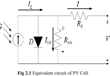
Fig 2.1 Equivalent circuit of PV Cell.
The PV generator is a non linear device and is usually described by its equivalent circuit and IV characteristics. The electric model of a solar system is composed of diode, two resistances and current generator [1]. The relation between the current (I) and voltage (V) is given by,
= − − 1 − (1)
Where Il, Io and I are the photocurrent, the inverse saturation current and operating current, Rs and Rp are the series and parallel resistances respectively which depend on the incident of solar radiation and the cell temperature. A= KT/q, where K and q are Boltzmann constant and electronic charges respectively. The equation (1) has rewritten as:
= − − 1 (2)
The current and voltage parameters of PV generator are Ipv=I and Vpv=nsNsVs , where ns and Ns are number of series cells in the solar panel and of series panels in the generator.
Fig 2.2 VI Characteristics of PV Panel
Figure 2.2 shows the characteristics of PV panel depends on the variation of irradiance. The short circuit current varies in proposition to the insulation level, while the open circuit voltage is approximately constant. Consequently the power will increase accordingly. Each curve has a maximum power point, which is the optimal operating point for an efficient use of solar array.
Boost Converter
Boost converter is a power electronic circuit which gives the output voltage is greater than the input voltage. It consists of dc input voltage Vs, boost inductor L, controlled switch S, diode D, filter capacitor C and load resistance R. When the switch S is on state, the current in the boost inductor increases linearly and the diode D is off at that time and the same time the inductor stores the energy. When the switch S is off, the energy stored in the inductor is released through the diode to the output RC circuit. Now the output voltage is the sum of the input voltage and the inductor voltage [5]. The circuit diagram of boost converter is shown in the figure 3.1.
Fig 3.1 Circuit diagram of Boost converter.
Using Faraday’s law for the boost inductor is given by,
= ( − )(1 − ) (3)
From which the dc voltage transfer function turns out to be,
= = (4)
As the name of the converter suggests, the output voltage is greater than the input voltage. The boost converter operates in the CCM for L> Lb where
=( )( ) (5)
International Journal of Current Advanced Research Vol 8, Issue 06(C), pp 19171-19175, June 2019
Pwm Inverter
The voltage source inverters are widely used in power supply, renewable energy, marine and military applications. If the input dc is a voltage source, then the inverter is called as voltage source inverter. It is important that they are designed to be robust and efficient, especially in remote areas and renewable energy application.
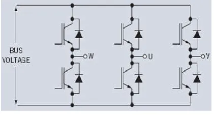
Fig 4.1 Three phase Voltage Source Inverter circuit.
The figure 4.1 shows the three phase voltage source inverter. The full bridge three phase inverter consists of dc voltage source, six semiconducting switches and a load. The semiconducting switching nowadays are BJT, IGBT, Thyristor and GTO [3]. The diodes provide as an alternate path for the load current if the power switches are turned off. Control of the circuit is accomplished by varying the turn on time of the upper and lower MOSFET of each inverter leg with the provision of never turning ON both at the same time, to avoid a short circuit of DC bus [4]. The control pulse to the swatches may be generated by either microcontroller or DSP. A variable voltage can be obtained by varying the input dc voltage and maintaining the gain of the inverter constant. On the other hand, if the dc input voltage is fixed then variable output voltage can be obtained by varying the gain of the inverter. This can be accomplished by pulse width modulation (PWM) technique within the inverter. PWM means the width of the square pulse in positive and negative halves can be adjusted according to the RMS of the output obtained. The inverter gain is defined as ratio of ac output voltage to the dc input voltage. Here, the input to the inverter is supplied from the boost converter and expected output voltage is 210 V.
Mathematical Model of an Induction Motor
In modelling of an induction motor, both the stator and rotor windings carry alternate currents. The stator produced flux rotates at synchronous speed with respect to stator. The currents induced in the rotor also produce a field that rotates at synchronous speed with respect to stator. Thus under steady state conditions, the relative speed between stator and rotor field is zero [6]. Note that the rotor receives energy from stator by electromagnetic induction. The object of the induction machine analysis under dynamic, transient and steady state conditions[3]. The mathematical model of an induction motor equations are as follows as:
The voltage supply for an induction motor is
Va=[V]sin(wt+ ) (6)
Vb=[V]sin(wt-2π/3+ ) (7)
Vc=[V]sin(wt-4π/3+ ) (8)
The voltage equation from three phase to two phase is 2 Vqs=Ö2/3( Ö Vb -Ö Vc) (10)
These voltage equation written from the matrix form as Vds=RdsIds+LdsIdsP+LmdPIdr (11)
Vqs=RqsIqs+LqsIqsP+LmqPIqr (12)
Vdr=LmdIdsP-LmqwrIqs+RdrIdr-LqrwrIqr (13)
Vqr=LmqIdsP+LmdwrIds+RqrIqr+LdrIdrwr+LqrIqr (14)
The equation for the electrical model as Induced EMF = (15)
. = (16)
∫ . =i(t) (17)
i(t) = . ∫ (18)
i(t) = . ∫( − ) (19)
The three phase current is converted to two phase current, When =0 the equation are as = ∗ (20)
= ∗ [ − − √ ] (21)
= ∗ [ − + √ ] (22)
Similarly for the torque equation to model for an induction motor are as follows as = [ [ + ] − [ + ] (23)
= ( − ) (24)
The relations between torque and speed equations are = + + + (25)
− = + (26)
− = . . + (27)
− = [ . + ] (28)
[ . ]= (29)
[ . ] = (30)
The voltage, current and torque equation which is controlled by the vector control of an induction motor.
Scalar control of ac drives produces good steady state performance but poor dynamic response. This manifests itself in the deviation of air gap flux linkages from their set values. This variation occurs in both magnitude and phase[4].
Vector control (or field oriented control) offers more precise control of ac motors compared to scalar control. They are therefore used in high performance drives where oscillations in air gap flux linkages are intolerable, e.g. robotic actuators, centrifuges, servos, etc.
Why does vector control provide superior dynamic performance of ac motors compared to scalar control ?
In this paper, direct vector control is used. control depends on the generation of unit vector s
the stator or air gap flux signals. The air gap signals can be measured directly or estimated from the stator voltage or current signals. The stator flux components can be directly computed from stator quantities. In these systems, rotor speed is not required for obtaining rotor field angle information. Here, the actual motor currents are converted to synchronously rotating frame currents using park transformation. The resulting dc quantities are compared with the reference d and q-axis components. The output of the controllers are used to generate the pulse width modulated signals for switching the devices in the inverter bridge feeding the motor.
SIMULATION AND RESULTS
In this simulation model, the PWM inverter input voltage is fed from the solar panel. The output voltage of the solar panel is very low to run the motor, hence boost converter is implemented. From the boost converter, it will give the voltage supply to the PWM Inverter.
The induction motor is fed by a current controlled PW inverter with six semiconductor switching devices. The PWM current controllers are widely used. The switching frequency is usually kept constant. They are based in the principle of triangular carrier wave of desire switching frequency and is compared with the error of controlled signal. The error signal obtained from the sum of reference signal generated in the controller and the negative of the actual motor current feedback from the motor. The voltage signal obtained triggers the gates of the voltage source inverter to generate the desire output. If the error command is greater than the carrier, the inverter leg is held switched to the positive polarity. When the error command is less, the inverter leg is switched to negative polarity. This will generate the PWM signal and the output voltage of the inverter is proportional to the current error command.
Fig 6.1 Speed Control of an induction motor.
The direct vector control depends on the generation of unit vector signals from the stator or air gap flux signals. The air gap signals can be measured directly or estimated from the stator voltage or current signals. The stator flux components can be directly computed from stator quantities. In these systems, rotor speed is not required for obtaining rotor field angle information. Here, the actual motor currents are converted to synchronously rotating frame currents using park transformation. The resulting dc quantities are compared with the reference d-axis ponents. The output of the controllers are used to generate the pulse width modulated signals for switching the devices in the inverter bridge feeding the motor.
In this simulation model, the PWM inverter input voltage is the solar panel. The output voltage of the solar panel is very low to run the motor, hence boost converter is implemented. From the boost converter, it will give the voltage
The induction motor is fed by a current controlled PWM inverter with six semiconductor switching devices. The PWM current controllers are widely used. The switching frequency is usually kept constant. They are based in the principle of triangular carrier wave of desire switching frequency and is h the error of controlled signal. The error signal obtained from the sum of reference signal generated in the controller and the negative of the actual motor current feedback from the motor. The voltage signal obtained triggers rce inverter to generate the desire output. If the error command is greater than the carrier, the inverter leg is held switched to the positive polarity. When the error command is less, the inverter leg is switched to negative the PWM signal and the output voltage of the inverter is proportional to the current error
Speed Control of an induction motor.
Fig 6.2 Simulation circuit of PWM current Circuit
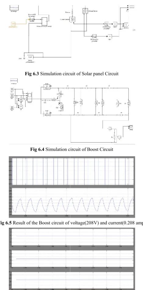
Fig 6.3 Simulation circuit of
Fig 6.4 Simulation circuit of Boost Circuit
Fig 6.5 Result of the Boost circuit of voltage(208V) and current(0.208 amp)
Fig. 6.5 Result of the Current, Voltage and Power of the Solar panel circuit.
circuit of PWM current Circuit
Simulation circuit of Solar panel Circuit
lation circuit of Boost Circuit
Result of the Boost circuit of voltage(208V) and current(0.208 amp)
International Journal of Current Advanced Research Vol 8, Issue 06(C), pp 19171-19175, June 2019
Fig 6.6 Result of the Speed of an induction motor.
The output current and voltage of the boost circuit is shown in the figure 6.6. The output of the voltage is 208 V which is given as the input dc voltage to the PWM inverter circuit. By using MATLAB, we will get the result of speed of an induction motor which is shown in the figure 6.5.
CONCLUSION
The work simulated in this paper proves the possibility of utilizing a PV cell to supply a three phase induction motor through three phase bridge inverter. We can conclude that this paper will be contribution to the analysis of solar panel to run an induction motor by means of boost circuit and PWM inverter. The experimental step up and its analysis may be considered as the future purpose.
References
1. Nafisa Binte Yousf, Khosru M. Salim, Rafid Haider, Md. Rajin Alam, Fatima Binte Zia, Development of three phase induction motor controller for solar powered water pump. IEEE Trans. Power Electron., Vol.24,no.5, pp. 1198-1208, May 2009.
2. W.V.Fam and M.K.Balachader, Dynamic performance of a dc shunt motor connected to a PV array. IEEE Trans. Energy conversion Vol.3, no. 3,Sept. 1989, pp 613-317.
3. Rashid, Muhammad H., Power Electronics-circuits, designs and applications, 2007.
4. Singh M.D, Khanchandani K.B., Power Electronics second edition, Tata Mcgraw Hill Publishing company limited, 2007.
5. N.Chandrasekaran and K.Thyagarajah, Modelling and performance study of single phase induction motor in PV fed pumping system using MATLAB, International journal of Electrical Engineering. ISSN 0974-2158 vol.5,no.3, pp. 305-316, 2012.
6. Betka. A, Moussi. A, Performance optimization of a photovoltaic induction motor pumping system. Renewable energy 29 (2004); 2167-2181.
How to cite this article:
Aravindaraj. K (2019) 'Modelling and Simulation of an Induction Motor Using Solar Panel', International Journal of Current Advanced Research, 08(06), pp. 19171-19175. DOI: http://dx.doi.org/10.24327/ijcar.2019.19175.3686