263 Abstract—The phenomenon of Stability of Modern Power Systems has received a great deal of attention in recent years. With the increasing complexity of the Modern Power Systems, the system stability is affected by Low frequency oscillations produced in the system. This paper provides a systematic approach to design a damping controller to damp the oscillations based on Bio inspired Genetic Algorithm(GA).The design problem is formulated as an Multiobjective Optimization criterion comprising of Eigen value based and Time domain based objective functions to compute the optimal controller parameters. The main objective here is to shift the closed loop eigen values to better positions in s plane and also to minimize the integral squared error involving rotor speed and power angle deviations so that the system stability will be enhanced to a greater extent. To validate the effectiveness and robustness of the proposed controller, Non linear simulations has been implemented under various system operating conditions and also introduction of disturbances in the form of outage of Transmission line in the system considered. The proposed controller design is also compared with the conventional Lead lag controller design to show the importance of the proposed Bio inspired controller design.
Index Terms—Genetic Algorithm, Multiobjective function, Power System Stability, Robust Control.
I. INTRODUCTION
The application of Bio inspired Genetic Algorithms to Power system stability problems has recently attracted the attention of researchers in the field of Artificial Intelligence. Low frequency inertial oscillations, with frequencies ranging from 0.1 to 2 Hz are inherent to Electric power systems[1].Problems due to inadequate damping of such oscillations have been encountered throughout the history of Power Systems. The use of supplementary controls is generally the only practical method of mitigating the oscillations, without resorting to costly operating restrictions or transmission reinforcements. A Power System Stabilizer (PSS) is one of the most cost effective method to damp the oscillations, thus enhancing Power system stability [2].Most PSSs employ the classical linear control theory [3-4].
Manuscript received July 20,2009.
R.Shivakumar is with Department of Electrical and Electronics Engineering, Sona College of Technology, Salem-636005, Tamilnadu,India (email : [email protected]).
Dr.R.Lakshmipathi is with Department of Electrical and Electronics Engineering, St.Peters Engineering College, Chennai, India(email : [email protected]).
Y.Suresh is with Department of Information Technology, Sona College of Technology, Salem-636005,Tamilnadu,India(email : [email protected]).
Despite the potential of modern control techniques like optimal control, adaptive control, variable structure control [5-6], Power System utilities still prefer the conventional lead lag PSS structure. PSS design approach is based on a linear model in fixed configuration of the power system. This results in fixed parameters of PSS. The Power system being dynamic and Nonlinear in nature, fixed setting of the controller parameters degrades its performance. Unfortunately, the conventional techniques are time consuming, as they are iterative and require heavy computation burden and slow convergence. To have controllers provide good damping over a wide operating range, its parameters need to be fine tuned in response to the oscillations to fit the system requirements to various modes of oscillations.
Modern Bio inspired algorithms include a wide variety of population based algorithms which can be applied to different kinds of optimization problems. Recently, Bio inspired optimization techniques like Genetic algorithms, Tabu search, Evolutionary Programming, Simulated annealing, Bacteria foraging and Particle Swarm Optimization have been applied for PSS parameter optimization [7-8].
In this work, Genetic Algorithm is implemented to compute the optimal controller parameters for enhancing system stability. Genetic Algorithms are computerized search and optimization algorithms based on the principles of Natural genetics and Natural selection [9].GA mimic the survival-of-the fittest principle of nature to make a search process. Genetic algorithm differ from more traditional optimization techniques in many ways: Genetic algorithm use objective function to guide the search, not derivative or other auxiliary information. Genetic algorithm search through many points in the solution space at one time, not a single point.
The main objective here is to shift the weakly damped electromechanical mode Eigen values to stable locations in the complex s plane for system stability. The objective also involves minimization of integral squared error (Rotor speed deviation and Power angle deviation) to damp the low frequency oscillations. Non linear Time domain simulations under wide system operating conditions and system disturbances involving transmission line outage has been carried out to show the robust control property of the proposed optimal controller design.
The Complete design procedure is compared with the conventional lead lag stabilizer (CPSS) design to validate the superiority of the Bio inspired Genetic algorithm based stabilizer (GAPSS) design.
Implementation of Bio Inspired Genetic
Optimizer in enhancing Power System Stability
264 II. MODELING OF POWER SYSTEM
A. Power System model investigated
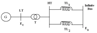
Fig(1) Single Machine Infinite Bus Power system Model
Figure (1) represents a 2220MVA, 24KV, 60 Hz Synchronous generator connected to an infinite bus through a step up Transformer (T) and double circuit transmission line. Et and EB being the generator terminal voltage and Infinite
bus voltage respectively. All the system parameters use for simulation [10] are given in Appendix-I.
For Analysis and Simulation, the Heffron-Phillips block diagram of Single Machine Infinite bus Model was used [11].
The Dynamic model in State Space form is given by
x= Ax+Bu
.
(1)
where [x] = Vector of State variables.
A, B = State Vector Matrix and Input Matrix respectively.
The State variables used in the modeling for open loop and closed loop system are given by,
[ ] [
x Eq Efd]
Topen= Δ
ω
Δδ
Δ ' Δ[ ]
x[
Eq Efd P UE]
T Closed= Δ
ω
Δδ
Δ ' Δ Δ 1 Δ(2)
The abbreviations for the variables are given in Appendix-II
B. Structure of Power system Stabilizer
Fig(2) Structure of Power System Stabilizer
The PSS model consists of the Gain Block, Cascaded identical Phase Compensation block and the washout block as in figure(2). The input to the controller is the Rotor speed Deviation (Δω) and output is the Supplementary Control signal (ΔUE) given to Generator excitation system.
The transfer function of the PSS Model is given by
(
)
(
)
(
(
)
)
(
( )
)
⎥⎥⎦ ⎤ ⎢ ⎢ ⎣ ⎡ + ⎥ ⎥ ⎦ ⎤ ⎢ ⎢ ⎣ ⎡ + + ⎥ ⎥ ⎦ ⎤ ⎢ ⎢ ⎣ ⎡ + + = ⎥ ⎦ ⎤ ⎢ ⎣ ⎡ Δ Δ T T T T TT U w w E s s s s s s Ks 1 1 1 1 1 4 3 2 1 ω (3)Where Ks = PSS gain
Tw = Washout Time constant. T1,T2,T3,T4 = PSS Time constants
For the identical phase compensator block, the Time Constants T1 = T3, T2= T4.Hence Ks, T1, T3 are the PSS
parameters which should be computed using Conventional Lead Lag stabilizer and optimally tuned using Genetic based
stabilizer.
The washout time constant is in the range of 1 to 20 seconds and in this work, Tw is taken as 10 seconds.
III. PROPOSED OPTIMIZATION CRITERION
A. Criteria for Stability
For the System to be stable, all the system Eigen values should lie on better positions in left half of the complex s plane.
The Oscillatory mode (Electromechanical mode) is represented by an Complex Eigen value (σ ± j ω).The Real part(σ) of a complex Eigen value indicates whether an oscillation decays(the real part is negative), remains at a constant amplitude(the real part is zero) or grows(the real part is positive).
B. Multi objective function formulation
The Main objective of this formulation is to compute the optimal value of PSS parameters for system oscillations damping and thus enhancing system stability
1).Eigen Value Based objective function
1 Max i , i EM
J
⎡σ σ σ
⎤ ⎡ ⎤= ∈⎣ ⎦ ⎣ ⎦ (4)
Where σi = Real part of the ith Electromechanical
Mode Eigen value.
σEM = Set of Electromechanical Mode Eigen
values.
The objective here is to Minimize the objective function J1,
so that the real part of the Electromechanical mode Eigen value is shifted to left half of s plane for system stability.
The Maximum value of the real part of the electromechanical mode eigen value will be located in right half of s plane,thus making the system unstable.
2).Time Domain based Objective function.
2 2 0 ( ) . S t dt T
J
⎡e
⎤⎡ ⎤=
⎣ ⎦
∫
⎢⎣ ⎥⎦ (5)Here e(t) is the error involving Rotor Speed deviation [Δω] and the Power angle deviation[Δδ].
Ts represent the Time of Simulation.
The objective here is to Minimize the objective function J2,
so that the integral of the squared error deviation is minimized thus enhancing the damping of the low frequency oscillations.
265 Optimize J
Subject to
m in m ax
S S S
K
≤K
≤K
(6)m in m a x
1 1 1
T
≤T
≤T
(7)m in m a x
2 2 2
T
≤T
≤T
(8) Typical ranges selected for Ks, T1 and T2 are as follows:For Ks [5 to 55], for T1 [0.1 to 1] and for T2 [0.1 to 1].This
Minimization criterion has been implemented in this work to compute the Optimum Value of the Parameters Ks, T1 and T2.
IV. BIO INSPIRED GENETIC ALGORITHM-AN OVERVIEW Genetic Algorithms are numerical optimization algorithms inspired by Natural selection and natural genetics [12].GA techniques differ from more traditional search algorithms in that they work with a number of candidate solutions rather than one candidate solution. Each candidate solution of a problem is represented by a data structure known as an individual. A group of individuals collectively comprise what is known as a population. GAs are initialized with a population of random guesses.
GA includes operators such as Reproduction, Crossover, Mutation and Inversion.
Reproduction is a process in which a new generation of population is formed by selecting the fittest individuals in the current population. Crossover is responsible for producing new offsprings by selecting two strings and exchanging portions of their structures. The new offsprings may replace the weaker individuals in the population.
Mutation is a local operator which is applied with a very low probability of occurrence. Its function is to alter the value of a random position in a string. Finally, Inversion is a process which inverts the order of the elements between two randomly chosen points on the string.
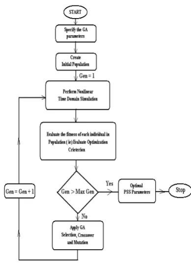
The Algorithmic Steps involved in Genetic Algorithm are as follows:
Step 1. Specify the various parameters for GA Optimization.
Step 2. Create an Initial Population of individuals randomly.
Step 3. Evaluate the fitness of each individual (i.e) Evaluating the optimization criterion J.
Step 4. If value of J obtained is minimum, then optimum value of PSS parameters is equal to those obtained in current generation, otherwise Goto step 5.
Step 5. Based on the fitness, select the best individuals and perform recombination through a crossover process.
Step 6. Mutate the new generation with a given Probability.
Step 7. If termination condition (Maximum no of Generations) is not reached, go back to step (3).
Fig (3) Computational Flow Chart for Genetic Algorithm
V. SIMULATION RESULTS
For all the Computation, Simulation and Analysis of the results in this work, MATLAB 7.0 / SIMULINK platform was used.
The Stability Analysis of the Test system is analyzed in 2 stages.
(1). Eigen Value Analysis.
This is done for the weakly Damped Electromechanical Modes. This analysis will determine their characteristics and sources of the problem and assist in developing Damping Measures. The Eigen values located in the left half of complex s- plane will determine the stability of the system, whereas the Eigen values located in right half of complex s-plane will make the system unstable.
(2). Non Linear Time domain Simulation.
This Analysis shows how system Non linearities affect the oscillations.
The State Space Modeling of the test system was performed and the Open loop Eigen values was computed as in Table III. The Electromechanical Modes of Oscillation indicate that the test system is Unstable, having positive real part Complex Eigen values located in right side of complex s plane.
266 Fig(4) Open Loop Speed Deviation response for
Operating Point (0.6, 0.03)
Fig(5) Open Loop Power angle Deviation response for Operating Point (0.6, 0.03)
The unstable system requires better damping design to mitigate the oscillations. In this work, Conventional Lead lag stabilizer (CPSS) and Genetic Based PSS (GAPSS) design is being implemented to compute the Optimal PSS parameters. Table I gives the various parameters selected for GA implementation.
TABLE I. PARAMETERS SELECTED FOR GENETIC ALGORITHM
Genetic Algorithm Parameters
Selected Values / Type
Population Size 20
No of Generations 10
Selection Operator Roulette Wheel Selection
Generation gap 0.9
Crossover Probability 0.95 Mutation Probability 0.10 Termination Method Maximum Generations
Implementation of CPSS and GAPSS provide the optimal PSS parameters (Ks,T1,T2) as listed in Table II.
TABLEII.OPTIMAL PSSPARAMETERS COMPUTED
S. No
Operating Conditions CPSS [Ks, T1, T2]
GAPSS [Ks, T1, T2]
1 P=0.6 Q=0.03
0.7951 0.6267 0.08
42.9023 0.5655 0.1463 2 P=0.5
Q=0.02
1.3449 0.4263 0.08
37.6909 0.7435 0.1004 3 P=0.6
Q=0.02+ Outage of Transmission Line TL2
0.8933 0.6120 0.08
49.0348 0.4690 0.1494
These optimal parameters computed from CPSS and GAPSS are utilized in calculating the closed loop eigen values of the system with controllers. The closed loop eigen values are listed in Table III. The eigen values reveal that the CPSS provide damping to the system by shifting the weakly damped electromechanical mode eigen values to the left half of complex s plane, making the system stable.
Comparatively, GAPSS provide better damping to the system by shifting the closed loop weakly damped electromechanical mode eigen values to better locations in s plane than the Conventional PSS, thus enhancing system stability to a greater extent.
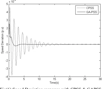
To validate the robustness and effectiveness of the proposed GAPSS, Non linear Time domain simulation (Based on minimizing the Integral Squared Error) has been carried out in this work under wide system loading conditions, and also introducing disturbances in the form of outage of the Transmission line (TL2).The error refers to the Speed
deviation and Power Angle deviation here.
Fig(6) and Fig (7) shows the Speed deviation and Power angle deviation response of the system operating at P=0.6, Q= 0.03 respectively. From the deviation response, it is clear that the GAPSS provide better damping to the oscillations compared to the CPSS.
267
TABLEIII . CLOSED LOOP EIGEN VALUES FOR OPEN LOOP,CPSS&GAPSS
S. No
Operating Conditions
Open Loop without PSS
CPSS GAPSS
1. P=0.6 Q=0.03
0.0822 ± j8.0704 -5.2151 ± j10.9396
-11.3272 -4.4981 ± j11.9196
-0.0499
-0.2212 ± j6.8184
-10.4896 -0.0499
-0.4185 ± j7.2271
-4.4716 ± j11.426 2. P=0.5
Q=0.02
0.2409 ± j7.5280 -4.8919 ± j11.5012
-11.3887 -4.3492 ± j12.4718
-0.0497
-0.3395 ± j6.3048
-4.0330 ± j12.6391 -10.9777
-0.0498
-0.6176 ± j5.6568
3. P=0.6 Q=0.02
+ Outage of Transmission Line
TL2
0.3953 ± j7.6858 -4.7444 ± j11.3502
-4.2184 ± j12.4207 -11.3336
-0.5045 ± j6.3069
-0.0496
-4.1813 ± j11.8658 -10.4353
-0.7406 ± j6.8499
-0.0499
Fig(7) Power angle Deviation response with CPSS & GAPSS for Operating Point (0.6, 0.03)
Fig(8) Speed Deviation response with CPSS & GAPSS for Operating Point (0.5, 0.02)
Fig(8) and Fig (9) shows the Speed deviation and Power angle deviation response of the system operating at P=0.5, Q= 0.02 respectively.
From the deviation response, it is clear that the overshoots are reduced and oscillations settle at a quicker stage by implementing GPSS.
Fig(9) Power angle Deviation response with CPSS & GAPSS for Operating Point (0.5, 0.02)
Fig(10) Speed Deviation response with CPSS & GAPSS for Outage of Transmission line(TL2)
Fig(10) and Fig(11) indicate the dominance of the Bio inspired stabilizer in damping the low frequency oscillations compared to the conventional controller.
268 Fig(11) Power angle Deviation response with CPSS & GAPSS for Outage of Transmission line(TL2)
These responses clearly indicate the damping phenomenon exerted by the various controllers. In all the cases, the Bio inspired algorithm based controller (GAPSS) provide better damping to the electromechanical oscillations compared to the conventional lead lag stabilizer.
VI. CONCLUSION
In this paper, a better and efficient solution to damp the low frequency oscillations which affect Power system Stability is presented. The Eigen value analysis and Non linear Time domain analysis clearly indicate the importance of Bio inspired Algorithm applications in mitigating the electromechanical oscillations, thus enhancing system stability. The Robustness of the proposed controller is clearly tested by simulating the system model under wide operating conditions and also introducing disturbance in the form of transmission line outage. Finally, the comparative study between CPSS and GAPSS clearly indicate the superiority of the proposed Genetic Algorithm based controller.
APPENDIX I
System Parameters:
Generator : 2220MVA, 24 KV, 60 Hz H = 3.5, Tdo’ = 8 secs, D=0 xd = 1.81, xd’=0.3, xq=1.76,xl =0.16 Excitation : IEEE ST1A type Excitation (For Speed input Stabilizer) KA = 190, TA =0, KF= 0,
TF =1Sec, VR min = -6.7, VR max = 7.8 Kc = 0.08, TB=10
Line : R=0.003, X (Line1) = 0.5, X(Line 2) = 0.93. Operating point (P =0.6, Q=0.03),EB = 0.995. All parameters are in p.u. unless specified otherwise.
APPENDIX II Abbreviations:
CPSS = Conventional Lead lag Stabilizer GAPSS = Genetic Algorithm Based Stabilizer
ω ,δ = Rotor Speed , Angle. KA = Amplifier Gain
EFD = Generator Field Voltage
Eq’ = Generator Internal Voltage.
ΔP1 = Output State Variable of PSS Washout Block. ΔUE = Supplementary Excitation Signal from PSS. σ = Real part of Eigen value.
REFERENCES
[1] X.Hugang,ch.Haozhong,L.Haiyu, “Optimal Reactive Power flow incorporating Static Voltage stability based on Multiobjective adaptive immune algorithm”,Energy Conversion and Management,vol.49,pp 1175-1181,2008.
[2] H.Shayeghi, A.Safari, H.A.Shayanfar, “Multimachine Power System Stabilizers design using PSO Algorithm”, International Journal of Electric Power and Energy Systems Engineering”, 1:4, pp.226-233, 2008.
[3] G.T.Tse and S.K.Tso, “Refinement of Conventional PSS design in Multimachine system by Modal Analysis”, IEEE Transactions on Power Systems, vol.8, pp.598-605, 1993.
[4] M.J.Gibbard, “Robust design of fixed parameter Power System stabilizers over a wide range of operating conditions”, IEEE Transactions on Power Systems, vol.6, pp.794-800, 1991.
[5] R.Segal, M.L.Kothari and S.Madnani, “Radial Basic function network adaptive Power System Stabilizer”, IEEE Transactions on PowerSystems, vol.15, No.2, pp.722-727, May2000.
[6] B.Changaroon,S.C.,Srivastava and D.Thukaram, “A Neural network based PSS suitable for ON line Training- A Practical case study for EGAT System,” IEEE Transactions on Energy Conversion,vol.15,No.1,pp-103-109,March 2000.
[7] Yamille del Valle,Ganeshkumar Venayagamoorthy,Salman Mohegheghi,Jean Carlos Hernandez,Ronald G.Harley, “Particle Swarm Optimization: Basic Concepts,Variants and Applications in Power Systems”,IEEE Transactions on Evolutionary Computation,Vol.12,No.2,April 2008.
[8] Jong Bae Park,Ki Song Lee,Joong Rin Shin,Kwang Y.Lee, “A Particle Swarm Optimization for Economic Dispatch with Non Smooth Cost functions”,IEEE Transactions on Power Systems,Vol.20,N0.1,Feb 2005.
[9] Y.L.Abdel-Magid and M.A.Abido, “Robust Coordinated design of excitation and TCSC based stabilizers using Genetic Algorithms”,
International Journal of Electric Power and Energy Systems, vol.69, No.23, pp 129-141, 2004.
[10] Prabha Kundur, “Power System Stability and Control”, Tata Mc Graw Hill, 5th Reprint, 2008.
[11] Bikash Pal, Balarko Chaudhuri,”Robust Control in Power Systems”, Springer Series,USA, 2005.
[12] A.Andreoiu, K.Bhattacharya,”Robust tuning of PSS using a Lyapunov Method based Genetic Algorithm”, IEE Proceedings on Generation, Transmission and Distribution”, vol.149, No.5, pp-585-592, September 2002.
R.Shivakumar received the M.E degree in Power System Engineering from Annamalai University, India in 1999.Currently he is working in Sona College of Technology, Salem, India as Assistant Professor in Electrical and Electronics Engineering department. He is now working towards his PhD in Electrical Engineering at Anna University, Chennai, India. His areas of research include Power System Dynamics, Optimization Techniques, FACTS and Power System Control and Operation. He is an annual member of IEEE and Life Member of ISTE.
Dr.R.Lakshimpathi received the B.E degree in 1971 and M.E degree in 1973 from College of Engineering, Guindy, Chennai.He received his PhD degree in High Voltage Engineering from Indian Institute of Technology, Chennai, India. He has 36 years of teaching experience in various Government Engineering Colleges in Tamilnadu and he retired as Principal and Regional Research Director at Alagappa Chettiar College of Engineering and Technology, Karaikudi.He is now working as Professor in Electrical and Electronics Engineering department at St.Peters Engineering College,Chennai.His areas of research include HVDC Transmission, Power System Stability and Electrical Power Semiconductor Drives.