JNEC, Aurangabad, India (MH)
Abstract: A number of variety of centrifugal pump have been constructed and used in many different applications in domestics, Agricultural, industry and other technical sectors. Due to the great number of free geometric parameters, their design and performance prediction process is still a difficult task, mainly the effect of which cannot be directly evaluated. Centrifugal pumps consume huge amounts of energy in various industrial applications. Therefore for these pumps, the improvement of machine efficiency has become a major challenge. Since the hydraulic performance of a centrifugal pump strictly depends on its impeller shape, in the present work, an efficient and original approach has been developed and applied to the design of centrifugal pump impellers in order to achieve a higher efficiency. An overview of the different inlet and outlet volutes for radial impellers. In this paper vibration of pump minimize by changing the centrifugal pump impeller outlet vane angle. Initially published two paper shows designing the pump impeller with new angle system, CATIA part analysis in ANSYS workbench which finds out 6 mode of natural frequency of vibration. Here it is shown experimental Result and FFT analysis result of new pumping systems. Which shown Vibration minimize, Performance increasing and mathematically shown life improvement
Keywords— Centrifugal Pump, Centrifugal Impeller, Pump Vibration, FFT analysis, Impeller.
I. INTRODUCTION
Centrifugal pump is a machine that imparts energy to a fluid. This energy can cause a liquid to flow or rise to a higher level. Centrifugal pump is an extremely simple machine which consists of two basic parts: The rotary element or impeller and the stationary element or casing. The centrifugal pumps are widely used in the world because the pump is robust, effective and inexpensive to produce. Centrifugal pumps are more economical to own, operate and maintain than other types of pumps. Pumps operate via many energy sources, including manual operation, electricity, engines, or wind power, come in many sizes, from microscopic for use in medical applications to large industrial pumps. Mechanical pumps serve in a wide range of applications such as pumping water from wells, aquarium filtering, pond filtering and aeration, in the car industry for water-cooling and fuel injection etc. This paper detail study existing pump system and changing outlet vane angle create new systems. When design complete then these both systems experimentally studied and compare the result. What changess happens in new pumping system that’s studied by experimentally, note down the vibration effect on performance and life of pump.
II. IMPELLER DESIGN
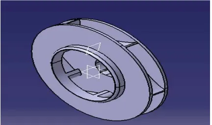
Fig.1. Pump impeller with a device:
1- pump casing, 2- impeller, 3- shaft; 4 – ball joint; 5, 6 –longitudinal seals of the impeller; 7 – annular chamber; 8- face seal; 9- radial vanes; 10 – lateral clearance of the impeller shroud.
A. IMPELLER DESIGN DATA
All below data generated for required Head hP = 12m (Considering 30% head loss in overall pump systems), required flow rate: Q = 10.4 LPS and Required speed N = 2600 RPM by using appropriate formulas
Diameter of suction flange, Dsu--- 66mm
Velocity in suction flange, Vsu --- 3 m/s
Shaft diameter, Ds--- 25 mm
Impeller hub diameter, DH--- 35 mm
Impeller eye diameter, D0---75 mm
Velocity through impeller eye,V0---3.1 m/s Diameter of inlet vane edge, D1---- 75 mm
Velocity at inlet vane edge, V1= Vf1--- 3 m/s
Passage width at inlet, b1--- 15 mm per side
Tangential velocity of inlet vane edge, u1--- 10.21m/s
Vane angle at inlet, --- 160
Impeller outlet diameter, D2---140 mm
Radial component of outlet velocity, Vf2--- 3 m/s
Vane angle at outlet, --- 240
Total passage width at outlet, b2--- 9 mm
Tangential velocity of outlet vane edge, u2----- 19.1 m/s
Absolute velocity leaving impeller,
V
2'--- 9.2 m/sTangential component of absolute leaving velocity,
V
w'2--- 8.65 m/sFig 3: Centrifugal pump impeller catia part
III. IMPELLER CHECK
As Impeller is made up by using Cast Iron and it is brittle material. When it is working condition that time load applied on the surface area of impeller is compressive in nature. So checking the impeller applying uniform compressive load and find out the maximum deformation of pump material. As deformation occurs it affect the performance of pump. Also considering pump work maximum allowable speed and find out vibration of pump and pump impeller. For the destruction of pump for vibration, when operating critical frequency of pump impeller match with the natural frequency of pump then destruction of pump occurs; so find out the natural frequency of pump impeller and our main aim is to keep the operating critical frequency below to natural frequency or always natural frequency greater than the operating critical frequency. This issue checks the pump using ANSYS V12 workbench for static structural load and modal analysis for vibration.
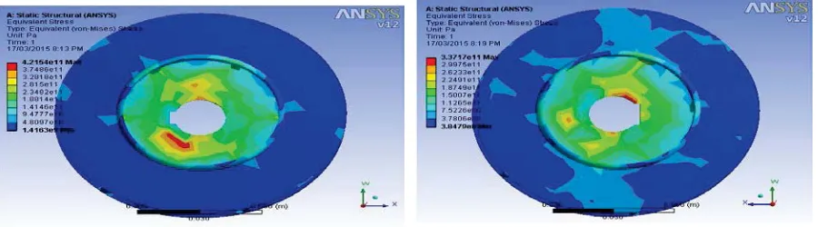
A. ANSYS V12 WORKBENCH FOR STATIC STRUCTURAL LOAD
In this case ANSYS V12 workbench used, in that case subpart static structural processor used for solution. In this case shaft hub used as fixed part and other loading condition used for all part of impeller uniform way. Rotation velocity of impeller is 2600 RPM; Hydrostatic pressure is 16m/s2 and calculated bending moment 277736 N-m is applying for find out the total deformation and Equivalent stress of pump impeller and in case of result section compared it for all four vane outlet angle 20 , 24 , 30 and 35 . Find out effect on impeller body when change in vane outlet angle 20 , 24 , 30 and 35 .
Fig 4: 24 and 30 outlet vane angle total deformation with static load condition
b. EQUIVALENT STRESS APPLYING STATIC LOAD
Fig 6: 24 and 30 outlet vane angle Equivalent stress with static load condition
IV. VIBRATIONS IN CENTRIFUGAL PUMPS
It is necessary to be interested in vibration in centrifugal pumps because it has a major effect on the performance. Generally, increasing vibration levels indicate a premature failure, which always means that the equipment has started to destroy itself. It is so because excessive vibrations are the outcome of some system malfunction. It is expected that all pumps will vibrate due to response from excitation forces, such as residual rotor unbalance, turbulent liquid flow, pressure pulsations, cavitation, and/or pump wear. The magnitude of the vibration will be amplified if the vibration frequency approaches the resonant frequency of a major pump, foundation and/or piping component. Generally higher vibration levels (amplitudes) are indicative of faults developing in mechanical equipment.
A. MECHANICAL CAUSES OF VIBRATIONS The mechanical causes of vibrations includes – · Unbalanced rotating components,
· Damaged impellers and non concentric shaft sleeves · Bent or warped shaft
· Pump and driver misalignment,
The peripheral causes of vibrations includes –
· Harmonic vibration from nearby equipment or drivers. · Operating the pump at a critical speed
· Temporary seizing of seal faces
V. ANSYS V12 WORKBENCH FOR MODAL ANALYSIS FOR VIBRATION
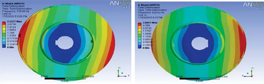
In this case ANSYS V12 workbench used, in that case subpart modal processor used for solution vibration check. In this case shaft hub used as fixed part and find out 6 mode of natural frequency of vibration. Find out the total deformation of pump impeller for lowest natural frequency of vibration and in case of result section compared it for all four vane outlet angle 20 , 24 , 30 and 35 . Find out effect on impeller body when change in vane outlet angle 20 , 24 , 30 and 35 .
A. TOTAL DEFORMATION OF IMPELLER WHEN IT VIBRATES IN NATURAL FREQUENCY
Fig 8: 24 and 30 outlet vane angle Total Deformation when it vibrates its natural frequency
Experimentally Find Out Efficiency
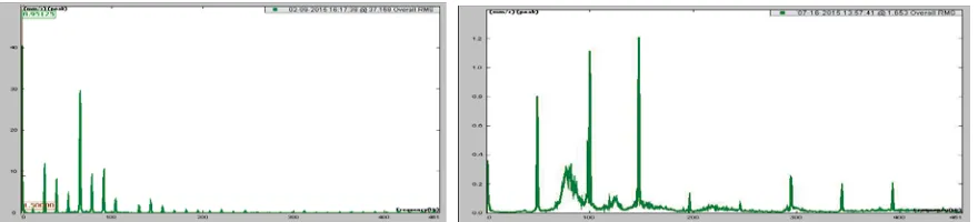
Fig. 10 : FFT result for old and new pumping systems
Vibration Effect on Pump Life
When Pump is in working condition that time vibration of pump occurs certain limit. In our old pump system impeller outlet vane angle are 300 that time first natural frequency 0Hz and exciting frequency 60Hz are close to each other because of that vibration resonance occurs. Because of resonance NPSC and bearing life minimize. When NPSH is minimize as compare to required NPSH it increase the cavitation problem of centrifugal pump impeller which reduce H & Q generation by pump which directly effect on the efficiency of pump. For old pump system, i.e. 300 operating frequency from FFT result is 60 Hz For this speed NPSH is 7.7 m of water
Similarly for new pump system i.e. 240 N=1500Rpm For this speed NPSH is 10m of water head
Cavitation of impeller reduce the life of impeller and increase the noise and unbalance force on all parts. This unbalance force reduce the bearing life of pump and bearing failure occurs. Because of bearing failure Prime mover i.e. Electric motor failure occurs Vibration Forces are Vibration is a dynamic response to a dynamic force, and an increase in force is extremely detrimental to bearing life, then, we also know that an increase in vibration (which results from an increase in forces) produces a corresponding decrease in bearing life which can be calculated. Also, if we know the source of the vibration and can reduce or eliminate this force, then a subsequent increase in bearing life can be expected.
Rule: Excessive vibration = excessive force = a reduction in bearing life VI. RESULT DISCUSSION
In this study finally we analysis that vane outlet angle 20 , 24 , 30 and 35 changes then in case statical load applying we found that total deformation and Equivalent stress are also changes. Total deformation of impeller goes on changes when vane angle increase total deformation up to 30 goes on decreasing and then again increasing for vane angle 35 .Similarly Equivalent stress of impeller goes on changes when vane angle increase stress up to 30 goes on decreasing and then again increasing for vane angle 35 .
Similarly when vane outlet angle 20 , 24 , 30 and 35 changes then natural frequency of vibration changes in modal analysis when vane outlet angle 20 high natural frequency but it decrease for 24 again it increase for 30 and again it decrease for 35 but all natural frequency is greater than critical frequency of vibration which is 260Hz for 2600 RPM and 6 vanes by calculation hence all vane angle are best to sustain for vibration state.
problem and cavitation
REFERENCES
[1] Asad Said Juma, Al Zadjali And G.R. Rameshkumar." Condition Monitoring Of Centrifugal Blower Using Vibration Analysis", International Journal Of Multidisciplinary Sciences And Engineering , vol.4, no.5, pp.50-59,June 2013.
[2] N.Yagesh Sharma and k.VasudevaKaranth “Numerical Analysis Of Centrifugal Fan For Improved Performance Using Splitter Vanes” World Academy Of Science, Engineering And Technology Vol 36, 2009.
[3] Donald R. Smith, Harold R.Simmons."Unique Fan Vibration Problems:Their Causes And Solutions". Proceedings Of The Ninth Turbomachinery Symposium, pp.33-43.
[4] Frantisek L. Eisinger, Robert E. Sullivan."Vibration Fatigue OF Centrifugal Fan Impeller Due TO Structural-Acoustic Coupling And Its Prevention: A CASE Study". Journal Of Pressure Vessel Technology,Vol.129,pp.771- 774, November2007.
[5] Robert J. Sayer, "Structural Dynamics Of Centrifugal Fans". Proceedings of the National Technical Training Symposium and 34th Annual Meeting of the Vibration Institute, Oak Brook, IL, June 2010.
[6] Robert J. Sayer, "Dynamic Testing Of Centrifugal Fan Wheels ". Proceedings of the National Technical Training Symposium and 34th Annual Meeting of the Vibration Institute, Oak Brook, IL, June 2010.
[7] Juan Gabriel Monge Gapper." Centrifugal Fan Impeller Failure Analysis Using Finite Elements".Ingeniería 16 (2):, ISSN: 1409-2441; San José, Costa Rica, pp.55-62, 2006.
[8] Veeranjaneyulu Itha, T.B.S.Rao, "Static And Dynamic Analysis Of A Centrifugal Blower Using FEA". International Journal Of Engineering Research And Technology(IJERT)ISSN:2278- 0181.vol.1,issue.8,pp.1-11,October2012
[9] Mohd Zubair, Ramavath Suman, M.Guru Bramhananda Reddy."Evaluation of Staticand Dynamic Analysis Of a Centrifugal Blower Using FEA". International Journal Of Adavnced Trends in Computer Science and Engineering ISSN:2278-3091, .vol.2,no.8,pp.316-321,January 2013.
[10] S.T.(Ted) Myrick. W.Barry Crawford, Gerald L. Schumpert., "Changing And Controlling The First Critical Speed Of Overhung Centrifugal Fans". Proceedings Of The Ninth Turbomachinery Symposium, pp.33-40.2004.