Abstract: Pump is used to convert mechanical energy into hydraulic energy; the task is to lift water from lower altitude and to deliver at high altitude. Impeller and casing are the major part of a centrifugal pump (CP), thus they have to be designed in a way that the pumps produces maximum efficiency. To achieve this Computational Fluid Dynamics Analysis (CFDA) is performed. It is a highly developed tools used in many industries. Complete CFDA was performed to forecast flow pattern at inner part of impeller. Results of analysis lead to forecast velocity and pressure at outlet of impeller. CFDA is done on ANSYS CFX software. In this paper, analysis is continued on existing impeller and modified impeller by varying its blade angle both at inlet as well as outlet Index Terms: CFD; Efficiency, impeller, Mixed flow, Performance.
I. INTRODUCTION
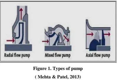
[image:1.595.70.269.566.702.2]The main function of pump is to lift liquids from lower altitude to higher altitude. To achieve this low pressure is created at inlet and high at outlet of pump. The energy conversion (mechanical into pressure energy) is done with the use of prime mover. Basically pumps are separated as positive displacement pumps and CPs this classification is based on how the liquid is passed, from suction to delivery side of casing. The CPs comes under cased pumps. In CPs the momentum of flowing liquid is increased with the help of impeller, a rotating element mounted to rotating shaft. Initially turbine pumps were utilized to transfer water from wells. Later on they have lot of application on various fields like cooling at industries, sea mining, irrigation, extraction of water etc. Further pumps are classified as radial flow pump, mixed flow pump and axial flow pump. Figure 1 represents the types of pumps.
Figure 1. Types of pump
( Mehta & Patel, 2013)
Revised Manuscript Received on April 07, 2019.
Deepak Kumar. Assistant Professor in Amity University, Gurgaon. Ph.D – Thermal Engineering (Pursuing From Delhi Technological University, Delhi ).
The energy of liquid increases when it has an axial and radial direction flow on mixed flow pump. In this pump liquid from the impeller is the mixture of axial and radial direction. The head of pumps are developed by stroke of centrifugal and propeller forces. These pumps have a major application towards irrigation purposes.CFD investigation is very much helpful on designing tool for machine in turbo commercial enterprise. The application of CFD towards the internal flow in pump impellers can decrease the time utilized in pump design procedure. The applications of CFDA on design of CPs are gradually increasing. The recent development in computing power with 3D graphics have influenced process of designing a CFD model and analyzing the results much easier and at least time and at best cost. In pump design CFD acts as a dominant tool. Many difficult problems are easily solved arithmetically and thus cheaper than performing experiments. However, a well unsteady flow in turbo machinery raise a question of most suitable process for modeling rotation of impeller.
II. LITERATURESURVEY
Damor et al., (2013), conducted an investigation, in CP. This has an outer impeller of 111mm diameter with blades curved (backward), 4.0 LPS of formal discharge and head at 12m. Design software is used to design impeller and CFDA were performed in ANSYS CFX software, in order to correlate the obtained results with experimental results of pump.
Chakraborty et al., (2013), performed investigation on 2-D steady, static pressure given out and incompressible flow characteristics with various blade numbers on inside passage of CP impeller. This work focus on effective competence of pump. Different CPs of 5-7 impeller blades are made and its efficiency is monitored at 3000 rpm via FLUENT 6.3 software. The numerical analysis reports that on increasing head as well as blades increases the static pressure. Performances of pump are based on the number of blades. Cheudhary et al., (2013), reveals an advance in impeller head of mixed flow pump, CFDA known to be an advanced
Computer Aided Engineering (CAE) utilized in
manufacturing of pumps. The pressure and velocity at impeller outlet can be predicted by CFDA and by means of empirical correlation; best possible inlet and outlet vane angles are found. Mixed flow impeller model are made on Solid Works with best suitable parameters. By altering blades and output blade angle of
Review Of Optimization Of Mixed Flow
Impeller Using Computational Fluid Dynamics
impeller, head of impeller is improved. The analysis shows that change in blade number and inlet angle of blade changes head of impeller. With help of CFD the optimum blade angles are calculated. Thus, by varying angle of blades and number of blades, head value of mixed flow impeller is enhanced. Manivannan. (2010) carried CFDA to forecast flow pattern within impeller, active component of pump. The outlet pressure and velocity of impeller is forecasted by results obtained in CFD. These parameters are utilized to find impeller efficiency. Through empirical correlations, various angles (van angle) are fixed for impeller. In order to know the link among vane angles and impeller performance best possible vane angle is achieved in different stages. Three various models with existing vane angle values of CP are
made and individually analyzed to evaluate
performance.Hedi et al., (2012), carried a numerical simulation on fluid flow in CP, governing equation for incompressible turbulent flows are used. The k-ε turbulence model is selected to express turbulent flow. Navier-Stokes equations are used to simulate flow inside vane less impeller. CFDA is gradually more functional in CPs designing. With aid of CFD pump design process can be easily performed with in short period of time. A method is found to gain 3D pressure and velocity ratio in CPs. This method involves completely elliptic partial differentials for conservation of momentum and mass. Joshi et al., (2010), analyzes pressure and velocity inside pump passage to examine pump efficiency with Fluent. Numerical model of impeller casing were generated with intricate internal pressure and velocity allocations are applied by coding. Velocity and pressure sharing directly impacts on stream variation wise location, inside CP. Mehta & Patel., (2013), carried a CFDA to forecast the exit parameters of impeller. These parameters are used to find out the efficiency of the impeller. By empirical correlations both vane angles are determined for impeller. From CFD analysis, at first outlet angle is greater, and at second inlet angle is smaller, variation in recirculation flow cause to get better efficiency. Head of impeller is enhanced by varying outlet angle. Finally, from
CFDA it is known that by varying inlet and outlet angle, the performance of impeller is enhanced. Kadam et al., (2011), performed numerical analysis to forecast flow inside entire pump impeller and casing.
III. PERFORMANCEEVALUATION
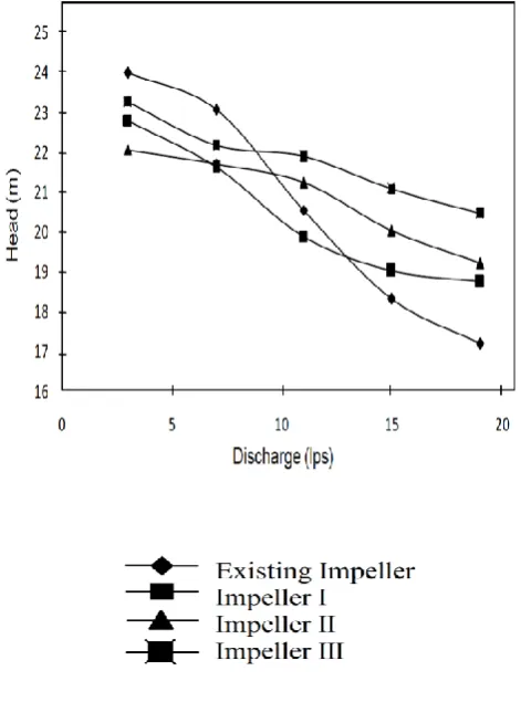
[image:2.595.305.541.229.552.2]Manivannan., (2010), performed CFDA on mixed flow pump and conclusions are made with results as follow.(See table 1) At 11LPS mixed flow pump shows best efficiency. For existing impeller efficiency, head and power rating are 55%, 19.2 m and 9.4 kW respectively.
Table 1. Various impeller designs
In impeller1, increased percentage in efficiency, head and power rating are 7.2%, 3.2% and 3.9% respectively. In impeller2, increased percentage in efficiency, head and power rating are 11%, 10.3% and7.6% respectively. In impeller3,
increased percentage in efficiency, head and power rating are 18.15%, 13.7% and12.16% respectively.
Figure 2. Head developed by existing and modified impellers (Manivannan 2010)
Impeller 3 has the best performance based on results. Using CFDA various design and operating parameter of pump is quickly calculated. The
proper design of impeller enhances the output. Patel et Impeller design Inlet angle(Deg.) Outlet angle(Deg.)
xisting 75 55
Impeller 1 75 60
Impeller 2 65 60
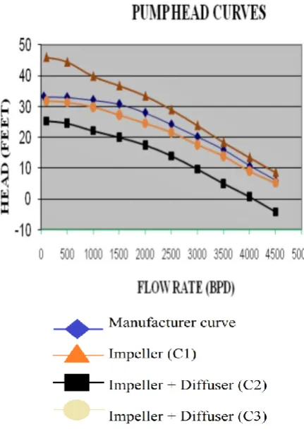
[image:2.595.40.271.606.697.2]al., (2006), performed CFDA of mixed flow pump found that forecasted head and power value by CFDA is high at rated point as compared with test results.
Figure 3. Head versus Capacity Curve(Patel et al., 2006)
The power value forecasted by CFDA is 5-10% higher at the point. The volumetric efficiency is found by comparing the test results intended by NEL method. The efficiency of pumps considering various losses was forecasted and found within +5 % ranges, at duty point and is shown in figure 4. Forecasted values are higher than test results. After matching the stator angle and changing hub curve profiles the efficiency is enhanced by 1%. Shroud and stator blade at hub are enhanced.
Figure 4. Efficiency versus Capacity Curve (Patel et al 2006)
Maitelli et al., (2010), carried analysis (CFD) of mixed low pump resulting mixed flow pump, to evaluate flow in CP impeller using Cartesian grid. The internal flow simulation ofCP was implemented. ANSYS CFX is used to acquire head performance curve also to find interface correlation among diffuser and impeller. Thus to distinguish 3-D problems, BC’s
[image:3.595.311.527.170.474.2]are adjusted in software. Although simplifications were completed with the model, to adjust geometry to software boundaries, numerical analysis by CFD, ANSYS CFX present outcome in concurrence with references. The 3-D simulation on entrance impeller contact with hydraulic disc pump. The obtained result for pressure fields, and head performance curve, were suitable with three testing conditions.
Figure 5. Obtained results of simulations and manufacturer head Curve.(Maitelli.,et al., 2010)
Patel et al (2012), analyzed impeller which is utilized in mixed flow submersible pump. To analysis Fluid flow (CFX) is used and it has constant mass as well as BC, i.e. inlet and outlet parameters was applied, shroud and hub was considered as wall. Pressure circulation and velocity on meridional view, blade-blade impeller was found. This revealed that generated head by CFX results good with experimental head.
Rajendran et al., (2012), performed work on simulation on impeller flow of pump with discharge and head as Q= 0.012 m3/sec and H= 10m respectively. The blade were loading at 50%span, average total pressure was obtainable. He predicted that head H = 9.45m by analysis (CFD). There is a incessant raise in pressure from leading to trailing edge, as a result of head on rotating pump.
Bacharoudis, et al., (2008), studied effects on blade outlet angle with CFD simulation. The results exposed that performance curve increases
[image:3.595.49.266.446.668.2]further. The study involves concert of impeller on same outlet diameter but varying angles of outlet blade. It is found and confirmed that increase in head is above 6%, when blade outlet angle is changed from 20° to50°.
Urankar et al., (2012), had reported the impeller and volute made by Walter K Jekat method and error triangle method, and this was modified in his work by varying vane inlet angle from hub to shroud.
Finally, a little twist at leading edge of the vane is achieved by varying leading edge angle from hub to shroud, leads to enhance the efficiency and small modification in vane results good.
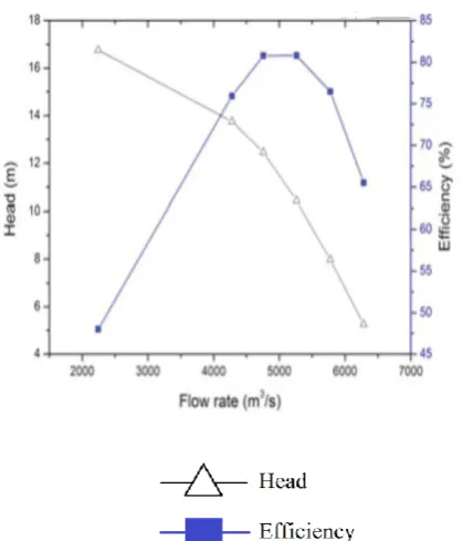
[image:4.595.309.512.106.257.2]Li, Jidong., et al., (2012), performed CFDA via optimum design on mixed flow pump showed that enlargement pump’s efficiency is improved significantly through volute inlet angle. Reduction of blades from 7 to 5 has greatly enhanced the overall design of mixed flow pump. Vertexes over blade’s head were reduced greatly by curve section. Optimum performance is achieved by (C-type) thereby properly increasing blade inlet angle followed with reducing the outlet angle. Model designed from 3D viscosity flow is simulated using FINETM and ANSYS CFX. Turbo module can be done on NUMECA software. These results can meet the engineering requirement.
Figure 6. Fitted head-flow rate and efficiency-flow rate curve of various calculating points of the Original pump
( Li, Jidong., et al., 2012)
Varchola., et al., (2012) carried geometry design which primly based from experimental results from impeller flow (internally)from mixed flow pump. Design procedure is carried via consideration in minimal losses. No availability pertaining with exact pattern for inlet-outlet passage. Suction parameter influences primarily on inlet geometry. Outlet geometry could be achieved via consideration of desired
[image:4.595.50.260.373.618.2]specific energy. The linear distribution of pressure from inlet to outlet should be considered while designing the impeller.
Figure 7 .Geometry of impeller (Varchola., et al., 2012)
Flow assumptions derived from 3-D analysis reported by Bing et al., (2013) exhibited better hydraulic performance along with an improved energy conversion capacity by blades when on comparison with flow assumptions of 2-D flow. The flow on each meridional streamline is same, satisfying the requirement of uniform circulation distribution on blade trailing edge. This shows that TDP has advantages over design method based on 2-D flow assumption.
[image:4.595.321.532.431.619.2]Figure 8(b) Meridional velocity distribution:impeller designed with TDP.TDP: 3-D design platform. (Bing., et al., 2013)
Wen-Guang, L., et al., (2011), found that Discharge blade angle tends to greatly influence over shift power as well as with its efficiency and pump’s head as well. From the relationship between flow rate and head curve (Figure 9)
indicates the viscosities ranges of: 1, 98 and 254 mm2/s.
Development of Higher head as a result of better angular
discharge. Viscosity ranges of over 1mm2/s, with a discharge
Q =8m3/h than that of zero flow rate.
Figure.9 (a) Head at BEP in terms of viscosity (Wen-Guang, 2011)
Figure: 9(b) hydraulic power at BEP in terms of viscosity (Wen-Guang, 2011)
Figure.9(c) efficiency at BEP in terms of viscosity (Wen-Guang, 2011)
Nataraj, M& R. Ragoth Singh (2014) identified contributions from different design parameters showed greater significance in determining its performance. Through conformation experiments that were conducted for verification of optimal grouping from obtained design parameters. The result were indicative and was in agreement with actual values in the case of static pressure as well as
[image:5.595.309.516.48.325.2] [image:5.595.49.261.51.256.2] [image:5.595.308.543.369.634.2] [image:5.595.49.266.411.672.2]impeller, thereby exhibiting better efficiency when on comparison to forward vane profile.
[image:6.595.317.536.61.307.2]Manivannan et al., (2010) studied CFDA in mixed flow pump. From the study it was observed that efficiency on the whole increased to 18.18% via changing its vane angle at inlet and outlet. Thus showing that in the existing impellers, it was seen that the discharge increased through reducing its head. As discharge rate increases, there is a substantial increase in fluid velocity, which in turn exhibited that the increased velocity consequences in drop in pressure. This in turn clearly indicative of the fact the through decreasing head aids in increasing the discharge. From the observed study, the characteristic curve representing discharge and head in the case of modified impeller 1 indicated manometric head to have increased to over 3.22% in its best efficiency point. By increasing the outlet angle paves for smoother flow alongside the exit region.
Figure 10. Head developed by the existing and modified impeller (Manivannan., et al., 2010)
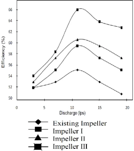
From Figure. 11. Showing characteristic curve that represents discharge and overall efficiency showed that the impeller’s overall efficiency tends to decrease after reaching 11 LPS. As a result of greater discharge rate, the fluid velocity increases significantly. This in turn causes cavitations losses as well as recirculation within the impeller.
Figure 11. Efficiency of existing and modified impeller (Manivannan, et al., 2010)
Chhanya & Thoriya (2014) observed that by incorporating filling impeller blades over its trailing edges considerably improves the pump’s performance. Best efficiency point in pump designed for study moves in ranges from 53 1/s - 56 1/s. The system efficiency also increased to about 2% which was observed to be the best efficiency point observed (Oh, 2010).
IV. CONCLUSION
Flow analysis observed on CPs often serves as tough task as requirements exhibited from critical analysis under highly complex flow/ turbulent as well as 3-D in nature with changes on curvature which is seemingly changing on a quick scale over flow passage. CFD approach is incorporated extensively for CPs primarily as an effective numerical simulation tool in performance prediction for design conditions, cavitation analysis, variable study, effects on various components, analysis of interface forecast of axial thrust, diffuser pump analysis on efficiency of pump in turbine mode, etc. URANS equations followed by two equation k-ε turbulence model found to showcase an appropriate value for attaining reasonable estimation in case of general performance of CP. From engineering perspective, those typical errors below 10% when revealed with experimental data.
Impeller and diffuser flows which were studied broadly and volute flow study noted as a remarkable research on further enhancement on efficiency of pump. 2-phase flow analysis involving slurry and cavitations flow and the pumps that are handling Non Newtonian fluid as well as fluid structure interaction are key
[image:6.595.62.277.303.591.2]Author-1 P
hoto
CFD studies aided in acquiring several advantages, compared to other techniques/approaches. However the empirical nature in case of validation of solution technique under experimental results appeared to be quite recommended under usual scenario. The findings from existing study facilitate researchers who are working under related studies. From the studies it can be concluded that there are many factors linked to performance of pump needs to discover. Performance of mixed flow pump could be enhanced by-
1. Decreasing blade numbers.
2. On increasing blade inlet and decreasing in blade outlet structure angles.
3. 3D flow is assumed during design the impeller. 4. The impeller blade thickness isreduced at periphery. Thus the study observed from the result showed that parameters that are experimentally analyzed could be effectively simulated under CFDA for attaining better results, prior it to its application. Besides it was noted from results showing that parameters that were experimentally verified and analyzed through CFD aids for better results. From the inferred literature survey that was studied from several authors over the years pertaining with fluid analysis. Kiranpatel and Ramakrishnan performed experiments towards predicting CFDA and its efficiency. The experimental studies indicated their efficiency to have significant impact as it was greater value compared to test results. CFDA of impeller head was predicted to be over 5-10% higher compare with test results that are attained from rated point. Manivannan performed CFDA as an effective tool for efficiently calculating cost effective, thus provides an optimal design which enhances the pump’s parameter. Through evolving a design that is quite suitable for improving efficiency of pump impeller by incorporating CFD analysis, as it tends to have a direct correlation with regards to improved design and output of submersible pumps.
REFERENCES
1. Damor,Jekim J., et al. "Experimental and CFDA of CP impeller-A case study." International Journal of Engineering Research & Technology (2013).
2. Chakraborty, Sujoy, et al. "Performance prediction of CPs with variations of blade number." (2013).
3. Chaudhari, S. C., C. O. Yadav, and A. B. Damor. "A comparative study of mix flow pump impeller CFDA and experimental data of submersible pump.”International Journal of Research in Engineering & Technology (IJRET) ISSN (2013): 2321-8843.
4. Manivannan, A. "Computational fluid dynamics analysis of a mixed flow pump impeller." International Journal of Engineering, Science and Technology 2.6 (2010).
5. Hedi, Lamloumi, Kanfoudi Hatem, and Zgolli Ridha. "Simulation study and Three-Dimensional Numerical Flow in a CP." International Journal of Thermal Technologies (2012).
6. Joshi, Rakesh, Satish Guide Kumar, and S. K.Mohapatra. Computational Investigation of Flow Field in a Centrifugal Slurry Pump. Diss. 2010.
7. Mehta, M., and P. Patel. “CFDA of mixed flow pump impeller.” International Journal of advanced Engineering Research and Studies 2.2(2013): 15-19.
8. Kadam, V. S., et al. "Design and development of split case pump using computational fluid dynamics." Institute of technology, Nirma University, Ahmedabad (2011): 1-4.
9. Patel, Kiran, and N. Ramakrishnan. "CFDanalysis of mixed flow pump. “International ANSYS Conference Proceedings. 2006. 10. Maitelli, CWS de P., F. V. M. Bezerra, and W. Mata. "Simulation of
flow in a CP of esp systems using computational fluid dynamics." Brazilian journal of petroleum and gas 4.1 (2010). 11. Patel, M. G., Dattatraya, S., & Patel, B. J. (2012). CFDA of mixed flow
submersible pump impeller. Indian Journal of applied research, 1(9), 97-100.
12. Rajendran, S., & Purushothaman, D. K. (2012). Analysis of a CP impeller using ANSYS-CFX. International Journal of Engineering Research & Technology, 1(3).
13. Bacharoudis, E. C., et al. "Parametric study of a CP impeller by varying the outlet blade angle." Open Mechanical Engineering Journal 2.5 (2008): 75-83.
14. Urankar, Swapnil, Dr HS Shivashankar, and Sourabh Gupta. "Design and CFDAof single stage, end suction, radial flow CP for mine dewatering application." IJREAS 2.2(2012):6-18
15. Oh, H. W. "Design parameter to improve the suction performance of mixed flow pump impeller.”Proceedings of the Institution of Mechanical Engineers, Part A: Journal of Power and Energy 224.6 (2010): 881-887.
16. Li, Jidong, et al. "Optimum design on impeller blade of mixed-flow pump based on CFD." Procedia Engineering 31 (2012): 187-195. 17. Varchola, Michal, and Peter Hlbocan. "Geometry Design of a Mixed
Flow Pump Using Experimental Results of on Internal Impeller Flow." Procedia Engineering 39 (2012): 168-174.
18. Bing, Hao, and Shuliang Cao. "Three-dimensional design method for mixed-flow pump blades with controllable blade wrap angle." Proceedings of the Institution of Mechanical Engineers, Part A: Journal of Power and Energy 227.5 (2013): 567-584.
19. Wen-Guang, L. "Blade exit angle effects on performance of a standard industrial centrifugal oil pump." Journal of applied fluid mechanics 4 (2011): 105-119.
20. Nataraj, M., and V. P. Arunachalam. "Optimizing impeller geometry for performance enhancement of a CP using the Taguchi quality concept." Proceedings of the Institution of Mechanical Engineers, Part A: Journal of Power and Energy 220.7 (2006): 765-782. 21. Chhanya, V. G., and P. J. Thoriya. "Review On Design Improvement
Of MixedFlow Pump." Development1.12 (2014).
22. Nataraj, M., and R. Ragoth Singh. "Analyzing pump impeller for performance evaluation using RSM and CFD." Desalination and Water Treatment 52.34-36 (2014): 6822-6831.
AUTHORSPROFILE
I am Mr Deepak Kumar. I am workimg as an Assistant Professor in Amity University, Gurgaon. Ph.D – Thermal Engineering (Pursuing From Delhi Technological University, Delhi )
M. Tech – Thermal Engineering (NIT Kurukhetra) IES 2009 Qualified, Gate Qualified – 2007,2009,2010,2011 Member of
International Association of Engineers
(IAENG) Member of Hong Kong Society of